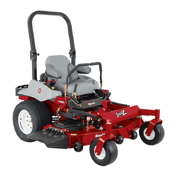
Exmark Lazer Z Operator's Manual
Zero-turn riding mower
Hide thumbs
Also See for Lazer Z:
- Installation manual ,
- Operator's manual (80 pages) ,
- Parts manual (36 pages)
Table of Contents
Advertisement
Advertisement
Table of Contents
Troubleshooting

Related Manuals for Exmark Lazer Z


Summary of Contents for Exmark Lazer Z
-
Page 2: Health Warning
Section 442 Public Resource Code. To acquire a spark arrester for your unit, see your Engine Service Dealer. Exmark reserves the right to make changes or add improvements to its products at any time without incurring any obligation to make such changes to products manufactured previously. - Page 3 3. Exmark being unable to ship the part and the Exmark parts order is received by 3:00 p.m., central time, Exmark pays for the part and freight. 4. If the part does not arrive overnight due to the shipper (UPS), the shipper pays for the freight and Exmark pays for the part.
- Page 4 Exmark equipment dealer or distributor. All Exmark equipment dealers and distributors are kept informed of the latest methods of servicing and are equipped to provide prompt and efficient service in the field or at their service stations. They carry ample stock of service parts or can secure them promptly for you from the factory.
-
Page 5: Table Of Contents
SAFETY Safety Alert Symbol ...1 Training ...1 Preparation ...1-2 Operation ...2-3 Maintenance & Storage ...4 Riding Attachments ...4 Safety Signs ...4-6 SPECIFICATIONS Model Numbers ...6 Engine ...6 Fuel System ...6 Safety Interlock System ...7 Steering/Brake Control ...7 Transmission ...7 Wheel Drive System ...7 Tires ...7 Deck ...7-8 2.10 Dimensions ...8... -
Page 6: Safety
RESULT IN PERSONAL INJURY IF PROPER PRECAUTIONS ARE NOT TAKEN. 1.2 TRAINING 1.2.1 Regard the Exmark mower as a piece of power equipment and teach this regard to all who operate this unit. 1.2.2 Read the instructions carefully. Familiarize yourself with the controls and the proper use of the equipment. -
Page 7: Operation
• • • • Fuel is Highly Flammable. DO NOT smoke while refueling. Refuel only in a well ventilated area, or refuel outdoors. • • • • Store fuel in containers specifically designed for this purpose. • • • • Add fuel before starting the engine. - Page 8 1.4.9 Start the engine carefully with feet well away from the blades. 1.4.10 Keep hands, feet and clothing away from rotating parts while the mower is being operated. 1.4.11 Stop the engine and disconnect the spark plug wire(s)and/ or remove key: a) Before checking, cleaning or working on the mower.
-
Page 9: Maintenance & Storage
1.5.11 All replacement parts must be the same as or equivalent to the parts supplied as original equipment. 1.6 RIDING ATTACHMENTS Use only Exmark riding attachments. Exmark riding attachments may create a hazardous condition resulting in injury. 1.7 SAFETY SIGNS 1.7.1 Keep all safety signs legible. - Page 10 PART NO. 323688 LOCATION: Console PART NO. 403005 LOCATION: Front Corners of Deck PART NO. 303517 LOCATION: Left Side, Rear Surface KAWASAKI,KOHLER & 10.5 HP B&S PART NO. 323689 LOCATION: RH Side of Console PART NO. 323550 LOCATION: Upper Handles (Both Sides) Engine Deck - 5 -...
-
Page 11: Specifications
PART NO. 403162 LOCATION: 48” Decks PART NO. 403143 LOCATION: Right Rear of Engine Deck PART NO. 303518 LOCATION: Transmission Shifter Plate 2. SPECIFICATIONS 2.1 MODEL NUMBER: Serial No.s 150,000 and Higher M3213KA; M3613KA; M3613KC; M3614KA; M3615KC; M4814KA; M4815KC. 2.2 ENGINE 2.2.1 Engine Specifications: engine owner's manual. -
Page 12: Safety Interlock System
2.3.3 Fuel Filter: Replaceable in-line 2.3.4 Fuel Shut Off Valve: in-line, 1/4 turn 2.4 SAFETY INTERLOCK SYSTEM Operator must have the transmission in neutral and blades disengaged to start engine. Release of Operator Presence Control (OPC) levers will cause engine to stop if transmission is not in neutral and/or blade drive is engaged. -
Page 13: Deck
2.9.6 Cutting Height: Adjusts in 1/4" (.63 cm) or smaller increments by various adjustments of caster spacers, blade spacers and axle height, from 1” to 4 1/4” (2.5 cm - 10.8 cm). 2.10 DIMENSIONS 2.10.1 Overall Width: 32" Discharge chute 42.45 in. - Page 14 Install casters to front of deck using appropriate hardware from the bolt bag (eight 3/8 x 3/4" bolts and eight 3/8" whizlock nuts); tightening the lower four bolts first, then the top four. Loosen the 5/16" hardware at the two (2) discharge deflector hinge points so that the deflector is snug, but can be moved up and down freely.
- Page 15 3.8.1 Attach throttle cable to engine. For Kohler, Kawasaki, and B&S 10.5 hp Engines with "positive" detents in throttle cable for both idle and full throttle positions. a) Position the throttle control lever (on console) in the full throttle (but not choke) position. You will feel a detent when the throttle control lever is approximately 3/4"...
- Page 16 KAWASAKI SPEED CONTROL (THROTTLE CABLE HOOK-UP) B&S 10.5 hp SPEED CONTROL (THROTTLE CABLE HOOK-UP) d) Pull cable upward (rearward for B&S) until alignment holes in control plate lever and control plate line up. For Kawasaki a 15/64 drill bit can be inserted through these two holes to align them.
- Page 17 For B&S 8.5 hp Engines, a) Position the throttle control lever (on console) 1/8" from the lower end of the slot. Route the throttle cable along the right side of the upper handle, under the fuel tank support, and position the cable on the left side of the engine.
- Page 18 FIG. 6 SHIFTER LEVER TO TRANSMISSION 3.8.5 Install and adjust wheel drive linkages. a) Screw threaded end of drive linkages into swivels in wheel drive idler arms. b) Insert clevis pin from bolt bag through drive linkage, lever and slot in the neutral lock/park brake latches (See Figure 9).
- Page 19 Neutral Lock / Park Brake Latch Drive Linkage NOTE: Neutral lock/park brake latch clearance should be checked when there is a slight upward force placed on the drive levers to remove any "slack" in the linkage. After clevis pin has been inserted, install hairpin into hole on the clevis pin between the neutral lock/park brake latch and drive lever (See Figure 11).
-
Page 20: Operation Instructions
3.8.8 Route the long, unattached wiring harness lead up the left hand side of the handle and connect the two leads, in any order, to the operator presence control switch terminals on the inside of the control console. Fasten the lead to the handle with two large wire ties, from bolt bag, one at the upper end of the handle next to the console and one at the very lower end of the handle where it attaches to the fuel... - Page 21 Park Brake Full Speed Forward DRIVE LEVER, NEUTRAL LOCK/PARK BRAKE LATCH OPERATION 4.1.4 Operator Presence Control (OPC) Levers: Located on the upper handle assembly directly above the handle grips. When these levers are depressed, the OPC system senses that the operator is in the normal operator's position.
-
Page 22: Pre-Start
a detent at the "idle" position, continuing rearward past this detent will shut off the engine B&S 8.5 hp Engines: For the B&S 8.5 hp engine the choke control is located on the left side of the engine (from operator's position). Pull the choke lever outward and to the rear (counter-clockwise from top). -
Page 23: Operating Instructions
• • • • If fuel is spilled, DO NOT attempt to start the engine. Move away from the spill and avoid creating any source of ignition until fuel vapors have dissipated. 4.3 OPERATING INSTRUCTIONS 4.3.1 Read the Engine Owner's Manual carefully for detailed operating instructions and maintenance regarding the engine. - Page 24 Close fuel shut-off valve if machine will not be used for a few days; when parking inside a building; or when transporting the unit. 4.3.4 Drive Lever/Neutral Lock/Park Brake Latch Operation: To lock the drive levers in “neutral” squeeze the drive levers back to the neutral position.
-
Page 25: Transporting
TRANSPORTING • • • • If loading with ramps, be sure ramps are properly supported and strong enough to support the unit. • • • • If necessary, use assistance when loading or unloading. Keep feet and legs out from under the unit when loading and unloading Be sure fuel shut-off valve is closed. - Page 26 Remove jack stands (or equivalent support) and lower deck to ground. BLADE BOLT INSTALLATION 5.1.4 Check safety interlock system. Service Interval: a) For your safety, your Exmark mower is equipped with Operator Presence Controls, referred to as (OPC). When Daily Be sure the spring disc FIG. 13 Daily...
- Page 27 OPC levers - the engine MUST stop. If the mower engine does not stop under any of the above mentioned conditions, DO NOT OPERATE. Contact your authorized Exmark service dealer. • • • • It is essential that all Operator Safety Mechanisms, be in place and in proper operating condition prior to mowing.
- Page 28 engines). Clean around oil filter and unscrew filter to remove. Before the new filter is installed, apply a thin coating of oil on the surface of the rubber seal. Turn filter clockwise until rubber seal contacts the filter adapter, then tighten filter an additional 2/3 to 3/4 turn.
-
Page 29: Lubrication Chart
5.1.11 Inspect belt wear. Service Interval: 40 hrs. a) Stop engine and remove spark plug wire(s). b) Remove the cutter deck belt shield to check mower primary and secondary blade drive belt condition. NOTE: A Secondary blade drive belt is used on 48" units. c) Look under engine deck to check the transmission drive belt condition. -
Page 30: Service Interval
c) Replace 5-speed gearbox grease yearly. Use 18 oz. Of Peerless grease (Part No. 788067). See Section 5.1.10. d) Lubricate pivot points with a spray penetrating lubricant as directed below. SPRAY LUBRICANT CHART PIVOT POINTS 1. Blade Engagement Bellcrank 5.1.13 Remove engine shrouds and clean cooling fins. Service Interval: See Engine Owner's Manual a) Stop engine and remove spark plug wire(s). -
Page 31: Adjustments
5.1.19 An anti-seize compound is used on the blade drive pulley hub, located on the engine PTO shaft (this allows for ease of removal of the pulley). 5.1.20 Dielectric grease is used on all blade type electrical connections to prevent corrosion and loss of contact. 5.2 ADJUSTMENTS 5.2.1 Adjusting cutting height with blade spacers. -
Page 32: Axle Height Adjustment
Refer to the charts and illustrations on the following pages to properly adjust for desired cutting height. FIG. 14 CASTER HEIGHT ADJUSTMENT These models have five (5) axle positions; four (4) 1/2" caster spacers; 3/16" caster Axle Pivot Bolt Place Jack Here Axle Adjustment Holes are actually in the side of the rear deck. - Page 33 NOTE: The axle positions are in 1/2" increments and the large caster spacers are 1/2" thick. Therefore, by adjusting the same number of 1/2" caster spacers as axle hole positions the blades will retain the same front-to-back tip (rake). CUTTING HEIGHT ADJUSTMENT (1" to 4 1/4") AXLE NO.
- Page 34 5.2.4 Wheel drive belts and scrapers. a) If wheel traction appears to be slipping, drive lever rods may be touching bottom of neutral lock/park brake latch slot. To adjust, refer to directions in Section 3.8.5. NOTE: There are three (3) adjustment holes for the wheel drive spring tension bolt (Refer to Section 5.2.15).
- Page 35 5.2.6 Secondary belt (48" only). a) Stop engine and remove spark plug wire(s). b) The secondary drive belt is adjusted via the belt tension rod (See Figure 16). The 5/16" nyloc adjustment nut is located at the rear, right corner of engine deck. c) Proper belt tension (for the secondary belt) will require about 10 lbs.
-
Page 36: Adjustments
turn setscrew all the way in then back out 1-1/2 turns. IMPORTANT: Screwing setscrew in too far will prevent the transmission from shifting. 5.2.12 Blade safety switch. a) Stop engine and remove spark plug wire(s). b) With the blades disengaged and the bellcrank touching the engine deck, adjust the blade safety switch (if needed) until the bellcrank depresses the plunger by 1/4". -
Page 37: Trouble Shooting
6. TROUBLE SHOOTING MOWER PULLING LEFT OR RIGHT. a) Check idler arm pulleys and drive sheaves for mud and/or grass buildup. Check for proper scraper position. b) Check to be sure idler arms pivot freely, if not, lubricate idler pivots. c) Check for worn drive belts. -
Page 38: Engine Troubleshooting
NOTE: After carefully checking the previous steps, attempt to start the engine. If it does not start, contact your authorized Exmark service dealer. When a problem occurs, do not overlook the simple causes. For example, starting problems could be caused by an empty fuel tank, key switch not "ON"... -
Page 39: Wiring Diagrams
8. WIRING DIAGRAMS - 34 -... -
Page 40: Warranty
This warranty is limited to one year from the date of original retail purchase (90 days for rental use) for any Exmark mower that is used for commercial or any other income producing purpose. The Blade Spindle assemblies will be warranted for three years, one year parts and labor with an additional two years parts only, form date of original retail purchase against defects in materials or workmanship. - Page 41 Exmark or any of its representatives to the buyer which relates to the goods that are the subject part of the basis of the bargain and shall not be deemed to create any express warranty that such goods shall conform to the affirmation or promise.
- Page 42 SERVICE RECORD Date Description of Work Done Service Done By - 37 -...
- Page 43 ALIGN THIS EDGE WITH A VERTICAL SURFACE (TREE, BUILDING, FENCE POST, POLE ETC.) - 38 -...
- Page 44 LINE OF PRODUCTS FOR TURF CARE ©1997,1998 EXMARK MFG. CO. INC. INDUSTRIAL PARK BOX 808 BEATRICE, NE 68310 ALL RIGHTS RESERVED SEE EXMARK’S COMPLETE ™ LAZER Z ™ LAZER Z ® EXPLORER ® TURF RANGER ® TURF TRACER ® TURF TRACER VIKING HYDRO ™...
Need help?
Do you have a question about the Lazer Z and is the answer not in the manual?
Questions and answers