Exmark LAZER Z Setup Instructions
Hide thumbs
Also See for LAZER Z:
- Installation manual ,
- Operator's manual (80 pages) ,
- Parts manual (36 pages)
Table of Contents
Advertisement
Quick Links
Loose Parts
Note: Use the chart below to verify that all parts have been shipped.
109-6181
Dealer Pack
Part #
Description
323-6
Cap Screw, Hex 3/8-16 x 1
98-5975
Washer, Belleville
3290-357
Nut, Hex Flange 3/8-16
103-1309
Warranty Registration Form
103-2106
Keys
32128-20
Nut, 5/16-18 Whizlock
1-303335
Tie, Plastic
109-6178
Literature Pack
Part #
Description
-----------
Manual, Operator's
-----------
Manual, Parts
109-3498
DVD, Exmark Safety Video
109-6435
Sheet, Emissions Warranty
Installing the Rollover Protection
System (Roll Bar)
1. Remove sides and top of crate from the base.
2. Remove roll bar components from the crate.
3. Remove roll bar tubes from sides of crate.
4. Remove the two brackets used to mount the
bottom of the upper roll bar tube to the crate.
5. Remove the 1/2-13 x 3 1/4 capscrews and 1/2-13
hex flange lock nuts from the two brackets at
each end of the upper roll bar tube and retain for
later use (Fig. 1).
6. Remove the (4) 1/4" lag screws holding the wheel
hub brackets to the crate bottom and discard.
FIGURE 1
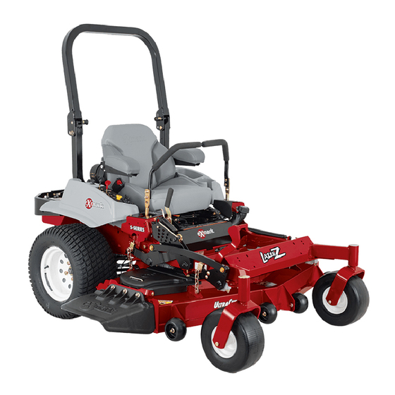
LAZER Z
SETUP INSTRUCTIONS
Qty
Use
8
8
Installing the Rollover Protection System (Roll Bar)
8
1
Fill out and return to Exmark
1
Unit ignition
4
For fastening seat tracks to unit seat frame
2
For fastening seat wiring to seat prop rod
Qty
Use
1
Read before operating machine.
1
1
View before operating machine.
1
7. Raise the rear of the unit approximately 10-12"
and support it with jack stands or equivalent
support.
POTENTIAL HAZARD
♦ Raising the rear of the unit for assembly relying
solely on mechanical or hydraulic jacks could
be dangerous.
WHAT CAN HAPPEN
♦ The mechanical or hydraulic jacks may not be
enough support or may malfunction allowing
the unit to fall, which could cause injury.
HOW TO AVOID THE HAZARD
♦ DO NOT rely solely on mechanical or hydraulic
jacks for support. Use adequate jack stands or
equivalent support.
8. Locate the left and right lower roll bar tubes.
9. Align lower roll bar tubes along rear engine frame
(Fig. 2).
10. LOOSELY install lower roll bar hardware (four
3/8-16 x 1 capscrews, four spring disk washers
and four 3/8-16 whizlock nuts) to the tubes on
each side. (Fig. 2).
®
(AIR COOLED)
For Serial Nos. 670,000 and Higher
CAUTION
Page 1 of 5
109-6182 Rev. A
Advertisement
Table of Contents

Related Manuals for Exmark LAZER Z


Summary of Contents for Exmark LAZER Z
- Page 1 Washer, Belleville Installing the Rollover Protection System (Roll Bar) 3290-357 Nut, Hex Flange 3/8-16 103-1309 Warranty Registration Form Fill out and return to Exmark 103-2106 Keys Unit ignition 32128-20 Nut, 5/16-18 Whizlock For fastening seat tracks to unit seat frame...
- Page 2 NOTE: Be sure the spring disk washer cone is Notes: installed towards the head of the capscrew. • Make sure the capscrew and nuts are installed with the nut to the inside of the roll bar. • Make sure the tab on the lanyard washer is installed as shown and points toward the front of the unit.
- Page 3 DANGER POTENTIAL HAZARD ♦ Charging the battery may produce explosive gasses WHAT CAN HAPPEN ♦ Battery gasses can explode causing serious injury. HOW TO AVOID THE HAZARD ♦ Keep sparks, flames, or cigarettes away from battery. ♦ Ventilate when charging or using battery in an enclosed space.
- Page 4 ends of clamp are approximately ½” (12.7 mm) apart. CAUTION Kawasaki POTENTIAL HAZARD 1. Remove air cleaner (with bracket attached) ♦ If the ignition is in the “ON” position there is and hose clamp from the carton located on potential for sparks and engagement of the floor pan.
- Page 5 cubby. Slide it on the air intake hose. Slide 7. If the ends of the levers hit against each other, the air intake hose onto the carburetor intake. while in the drive position (levers rotated in as Check to be sure the air cleaner intake hose far as possible), make adjustments by moving adequately engages the carburetor intake the levers outwards to the neutral lock position...
Need help?
Do you have a question about the LAZER Z and is the answer not in the manual?
Questions and answers