Weider Platinum XP600 User Manual
831.153992 resistance system exerciser
Hide thumbs
Also See for Platinum XP600:
- User manual (27 pages) ,
- User manual (27 pages) ,
- User manual (27 pages)
Advertisement
Model No. 831.153992
Serial No.
Write the seriaU number in the
space above for future reference,
Serial Number Decal (under seat)
• Assembly
• Adjustments
• Part List and Drawing
_CAUTmON
Read all precautions and instruc_
tions in this manuaJ before
using this equipment.
Save this
manual for future reference.
®
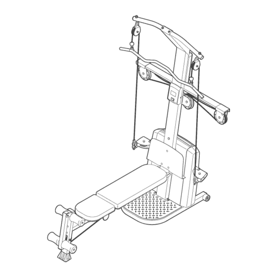
RESISTANCE SYSTEM EXERCISER
User's Manual
Sears,
Roebuck
and Co., Roffman
Estates,
IL 60179
Advertisement
Table of Contents

Related Manuals for Weider Platinum XP600


Summary of Contents for Weider Platinum XP600
- Page 1 Model No. 831.153992 ® Serial No. Write the seriaU number in the space above for future reference, Serial Number Decal (under seat) RESISTANCE SYSTEM EXERCISER • Assembly User's Manual • Adjustments • Part List and Drawing _CAUTmON Read all precautions and instruc_ tions in this manuaJ before using this equipment.
-
Page 2: Table Of Contents
TABLE OF CONTENTS WARNING DECAL PLACEMENT ............. HMPORTANT PRECAUTHONS ..............BEFORE YOU BEGIN ..............ASSEMBLY ................UPPER CABLE ADJUSTMENT .............. ADJUSTMENTS ................CABLE DHAGRAM ................. TROUBLESHOOTHNG ..............EXERCISE GUiDELiNES ..............ORDERING REPLACEMENT PARTS ..........Back Cover FULL ONE-YEAR WARRANTY ............Back Cover Note: A PART iDENTiFiCATiON CHART and a PART LiST/EXPLODED... -
Page 3: Warning Decal Placement
WARNING DECAL PLACEMENT :eep hands and ngers clear of _s area. Misuse of this product may resuHtin serious injury. Read user's manuaNand foNHow aNm w arnings and operating instructions prior to use. Do not allow children on or around machine. •... -
Page 4: Hmportant Precauthons
iMPORTANT PRECAUTIONS AWARN! NG: To reduce the dsk ofserious inju_y_ read t he fo,ow_ng important precautions before using the resistance system. Read all instructions in this manual before on the high cables only while sitting on the using the resistance system. -
Page 5: Before You Begin
BEFORE YOU BFGmN Thank you for selecting the innovative WELDER® after reading this manual, call 1-800-4-MYoHOME ® PLATINUM XP600 resistance system, The resistance (1 °800°469°4663), To help us assist you, please note system offers a selection of stations designed to devel- the product model number and serial number before op every major muscle group of the body, Whether your calling, The model number is 831,153992, The serial... -
Page 6: Assembly
Tighten all parts as you assemble them, unless Make Things Easier for Yourself instructed to do otherwise. This manual is designed to ensure that the resist- , As you assemble the resistance system, make ance system can be assembUed suceessfuUiy by sure all parts are oriented as shown in the draw- most peopb, However, it is important to realize ings,... - Page 7 Attach the Upright (3) to the Base (1) with two MIO x 66mm Carriage BoUts(89), two MIO x 72mm BoUts(87), and four MIO NyUon Locknuts (71) as shown. Note: This step will be easier to complete if the Upright and Base are tipped on their sides.
- Page 8 insert the connector of the lower wire harness (A) into the socket of the Upper Wire Harness (13), The connector should slide easily into the sock- et and snap into ptace, if the connector does not slide easily and snap into place, turn the connector over and then insert it, Make sure that the connector and wire appear as shown in the inset drawing, IF THE CONNEC-...
- Page 9 Grease an MIO x 69mm Boit (93), Orient the Leg Lever (32) with the shot on the side shown, Attach the Leg Lever to the Front Leg (31) with the Boit and an MIO Nyion Locknut (71), Do not over- tighten the Locknut;...
- Page 10 10, Attach the Lat Tower (5) to the Upright (3) with four MIO x 25mm Screws (100) and four MIO Lock Washers (74), Hug the Upper Wire Harness (13) into the Console (53), Push a!l of the excess wire into the Upright (3).
- Page 11 13. Pull the upper cabb (B), which is attached inside of the Mech Assembly (6), up between the Upright (3) and the Pulby Hate (18). Attach another Large Pulby (17) between the Upright (3) and Pulby Hate (18) with an M12 x 62mm Button Bolt (80) and an M12 Nylon Locknut (72).
- Page 12 17, HoUda Large Pulley (17) inside the upper came (B), Attach the Pulley to a Pulley Bracket (10) with an M12 x 58mm Button BoUt(81) and an M12 NyUon Locknut (72), Make sure that the cabJe is routed as shown in the CABLE DIAGRAM on page 18.
- Page 13 21, Locate the Leg Lever CabJe (62), which has two ends that are the same iength and a third end that is ionger, Route the iongest end of the Leg Lever CaMe (62) through the hob in the Front Leg (31), and attach it inside of the shot in the Leg Lever (32) with an MIO x 58mm Boit (94) and an MIO Nyion Locknut (71),...
-
Page 14: Upper Cable Adjustment
UPPER CABLE ADJUSTMENT After completing the assembly of the resistance system, the tension on the upper cable (B) will need to be adjusted, Also, the upper cable can stretch slightly when it is first used, When this occurs, the upper cable ten- sion will need to be readjusted, Follow the steps below to adjust the upper cable tension, Connect the two Tension Gauges (109, 110) together using the magnet,... -
Page 15: Adjustments
ADJUSTMENTS This section explains how to adjust the resistance system, See the EXERCISE GUiDELiNES on page 20 for important information about how to get the most benefit from your exercise program, Also, refer to the accompa- nying exercise guide to see the correct form for each exercise, Make sure all parts are properly tightened each time the resistance system is used, Replace worn parts immedio ately, The resistance system can be cbaned with a damp cloth and a mild, non-abrasive detergent, Do not use solvents, The resistance bar can be cbaned with a vinyl and rubber protectant, availabb at an automotive or... - Page 16 ATTACHmNG THEACCESSORmES Toattach a ShortHandHe (67)toa highpuHHey, first attach thehighpuHHey totheresistance s ystem (see ATTACHHNG THEHHGH PULLEYS o npage13),Then, attach theShortHandHe totheShort C abHe (60)witha CabHe CHip ( 64), TheLongHandles ( notshown) a ndtheAnkleStrap (notshown) c anbeattached tothelongcable(not shown) w ithCable CHips (64), A ttach theLegPress Strap (notshown) t o bothends of thelongcable,orthe LatBar(notshown) t otheShortCables (60),withtwo CableCHips,...
- Page 17 ADJUSTmNG THE BACKREST The Backrest (40) can be used in a bveU position or one of three inclined positions, To use the Backrest in a bveU position, secure the Seat Carriage (48) to the adjustment hob in the Bench Rail (23) next to the Front Leg (31) (see ADJUSTING THE SEAT on page 13), To use the Backrest (40) in an inclined position,...
-
Page 18: Cable Dhagram
CABLE DIAGRAM The cable diagram shows the proper routing of the upper cable (B), Use the diagram to make sure that the cable has been assembled correctly, if the cable has not been correctly routed, the resistance system will not function properly and damage may occur, The numbers show the correct route for the cable, Make sure that the ends of the cabJe do not wrap around each other between positions... -
Page 19: Troubleshoothng
TROUBLESHOOTmNG CLEANmNG THE BAR GUmDES Over time, dust may build up on the Bar Guides (55), causing a squeaking noise as the resistance system is used, Hfthis occurs, wipe off the Bar Guides with a damp cHothand a mild, non-abrasive detergent, Do not use soHvents, ADJUSTING THE RESISTANCE... -
Page 20: Exercise Guidelines
EXERCISE GUiDELiNES THE FOUR BASmC TYPES OF WORKOUTS PERSONALIZING YOUR EXERCISE PROGRAM Muscb Building Determining the exact length of time for each workout, as well as the number of repetitions or sets completed, To increase the size and strength of your muscles, is an individual matter, it is important to avoid overdo- push them close to their maximum capacity, Your mus- cues wHU continually adapt and grow as you progres-... - Page 21 Rest for a short period of time after each set. The slowly as you stretch and do not bounce, Ease into ideaU resting periods are: each stretch gradually and go only as far as you can Rest for three minutes after each set for a muscle without strain, Stretching at the end of each workout building workout.
- Page 22 MONDAY EXERCISE WEIGHT SETS REPS Date: AEROBIC EXERCISE TUESDAY Date: EXERCISE WEIGHT SETS REPS Date: AEROBIC EXERCISE Date: FRUDAY EXERCISE WEIGHT SETS REPS Date: Make photocopies of this page for scheduling and recording your workouts,...
- Page 23 MONDAY EXERCISE WEIGHT SETS REPS Date: AEROBIC EXERCISE TUESDAY Date: EXERCISE WEIGHT SETS REPS Date: AEROBIC EXERCISE Date: FRUDAY EXERCISE WEIGHT SETS REPS Date: Make photocopies of this page for scheduling and recording your workouts,...
- Page 24 PART iDENTiFiCATiON CHART Refer to the drawings beUow to identify small parts used in assemMy, The number in parentheses by each draw- ing is the key number of the part, from the PART LUST in the center of this manual Note: Some srnaH parts may have been pre-attached.
- Page 25 PART LiST--Model No. 831.153992 Ro3o4B Key No. Qty. Description Key No. Qty. Description Base CaMe Guide Base Hate Short Cabb Upright Tether Foot Hate Leg Lever CaMe Lat Tower Guard Hate Mech AssemMy CaMe CHp Front Mech Cover AnHe Strap Back Mech Cover Hip Strap Resistance Bar...
- Page 26 _105 _103 r"" 1 O3 ¢0 ,t,,,,O ¢0 lo9@ _oslod...
-
Page 27: Full One-Year Warranty
Get it fixed, at your home or ours! Your Home For repair - in your home - of all major brand appliances, lawn and garden equipment, or heating and cooling systems no matter who made it, no matter who sold For the replacement parts, accessories, and user's manuals that you need to do-it-yourself.
Need help?
Do you have a question about the Platinum XP600 and is the answer not in the manual?
Questions and answers