
Related Manuals for ICP NOMF105D12A


Summary of Contents for ICP NOMF105D12A
- Page 1 MULTI POSITION WARM AIR FURNACE Save these instructions for future reference. 02/05/22 X40094 Rev. A Printed in Canada 445 01 4094 00...
-
Page 2: Part 1 Installation
PART 1 INSTALLATION SAFE INSTALLATION REQUIREMENTS Installation or repairs made by unqualified persons can result in hazards to you and others. Installation MUST conform with codes or, in the absence local codes, with codes of the country having jurisdiction. information contained in this manual... -
Page 3: Locating The Furnace
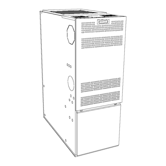
Before servicing, allow furnace tocool. Always shut off e lectricity and fuel t ofurnace when s ervicing. This wilI p revent electrical Your unit is equipped with safety devices that may keep it from shock orburns. operating if sensors detect abnormal conditions such as clogged k. - Page 4 As this unit may be installed as an upflow, counterflow or horizontal VENTING furnace (right or left), it may be located in a basement, on the same level as the area to be heated, suspended, or in a crawlspace. In any case, the unit should always be installed level.
-
Page 5: Air For Combustion
Inspection to ascertain that the vent system is clears and free of obstructions. Any blockage must be cleared before installing this furnace. ¢. Clearing the chimney or vent if previously used for venting a Poison carbon monoxide gas hazard. solid fuel burning appliance or fireplace. Confirming that all unused chimney or vent connections properly sealed. -
Page 6: Oil Tanks And Lines
Exposure tothese substances: Set your voltmeter to line voltage. Place one prong on your grounded electric entry box and one a. Permanent wave s olutions for h air. prong on the black wire. b. Chlorinated waxes and cleaners. Read the voltage. c. -
Page 7: Installing Accessories
NOTE: THE BACK SHOULD NOT BE CUT OUT FOR RETURN AIR Fire and explosion hazard. Provision is also made on this furnace for a bottom return air duct. Use only approved heating type oil in this furnace. Knockouts are provided on the floor of the furnace to facilitate the out requirement to assembly air filter... -
Page 8: Part 2 Operation
PART 2 OPERATION SEQUENCE OF OPERATION IMPORTANT The burner must be put in operation for at least 10 minutes before any test readings are taken. For new 1.1) Sequence of operation - Beckett AFG: installations, set up the burner to the settings (see table # 3), before firing. -
Page 9: Fan Adjustment
Remove the restriction and the burner should come back on in a few 2.4) FAN ADJUSTMENT CHECK minutes. This furnace is equipped with a 4 speed direct drive motor to deliver For year round air conditioning: a temperature rise within the range specified on the rating plate, between the return and supply pressure at the external duct static furnace... -
Page 10: Blower Removal
Do not tamper with the unit or controls. Call your service CAUTION technician, Be sure the blower is adequately supported when sliding out of the mounting rails, especially in the Before calling for service, check the following. horizontal, in order to prevent dropping the blower and Check oil tank gauge and check if the oil tank valve is open. - Page 11 PART 4 INFORMATION Model: Seria! number: Date of installation of the furnace : Service telephones - day : Night : Dealer's name and address : RESULT OF START-UP TEST Nozzle: Pressure : Burner adjustments : Primary air Fine air Draw Assembly Smoke scale : (Bacharach) Gross stack temperature:...
- Page 12 TABLE# 3 Technical s pecifications, NOMF Model : NOMF RATING AND PERFORMANCE Firing rate (USGPH) 0.65 0.75 0.85 1. ! Input (BTU/h) 70 000 91 OOO 105 0go 119 O00 140 0go 154 O00 Heating capacity (BTU/h) 57 00O 74 OOO 85 00O 97 OOO 1!5 0go...
- Page 13 VERSION EN FRANCAIS INCLUS DANS MANUEL I_/60HZ pOWER SUPPLY ,,ll_ L° FIoAPAc, oR D'INSTALLATION. (FUSEO DISCONNECT LEO] ,llll<_ ED MOT LEAE _> ]6_1 BLACK BLUE INPU BLUE LIMIT "11 COOLINO 3 TONS .,,& r,a ,1_ o" STANDARD HEAT / COOL WIRING DIAGRAM °b WITH ST9103 ELECTRONIC...
- Page 14 VERSION EN FRANCAIS INCLUS BANS MANUEL 60HZI pOICI_R SUPPLY D'INSTALLATION. I CAPAC'TOR (FUSED DISCONNECT LFG] ,lll_ CAPACITOR POWER SUPPLY BLACK BLACK LOMNN,MLc TRA_ R99GO01 BT91 LIMIT(S) BLUE 8_CN6 BLACK OIL INPUT : 1,00 USGPH BLUE COOLINO CAPACITY : 4 to 5 TONS <...
- Page 15 FIGURE # 3 Model: NOMF105D12A 1663 DNS-0832 Rev A TABLE # 3.2 Minimum clearances - combustion materials (in), MODEL: NOMF105D12A LOCATION APPLICATION UPFLOW DOWNFLOW HORIZONTAL SIDE FURN ACE SUPPLY PLENUM WITHIN 6 FT OF FURNACE BACK FURN ACE FURNACE OR PLENUM HORIZONTAL WARM AIR DUCT WITHING 6 FT OF FURNACE BOTTOM...
- Page 16 FIGURE # 3.1 Model: NOMF155E19A FOR6_ DIA FLUE TCPKN0CK OUT 1_oo 2_00 2900 _=_1259-- --19.00-- '#_J 5&00 01LINLET _(BOTH SIDE) laD_ 1_.75 DNS-0833 R@v. A TABLEAU # 3.3 Minimum clearances - combustion materials (in), MODEL: NOMF155E19A LOCATION APPLICATION UPFLOW DOWNFLOW HORIZONTAL SIDE F U RN AC E...
- Page 18 ModUle : NOMF105D12A PARTS LIST I =] =_._"_e,,] ;.41M/ [e] _ _[I LV_l:!--;.i [.e,[e] L v_ I Lv_ I --_ I Er_ Heat exchanger B01667 Back panel ass'y B01728 INCLUDES PANEL, INSULATION BAFFLE Back panel insulation B01526-11 Left back baffle B01686-02 Right back baffle B01686-01...
- Page 19 DETAIL " DETAIL "A"...
- Page 20 PARTS LIST ModUle : NOMF155E19A 1l]2_"[e_:ltUl [el _ !LIJLVil =!2=• =KO]Lv_ h V_l=l_ i IK Heat exchanger B01787 Back panel ass'y B01877 INCLUDES PANEL, INSULATION BAFFLES Back panel insulation B0!526-25 Left back baffle B0!806-02 Right back baffle B0!806-01 Right side panel ass'y B0!875-01 INCLUDES...
Need help?
Do you have a question about the NOMF105D12A and is the answer not in the manual?
Questions and answers