Advertisement
NDN5/GDJ
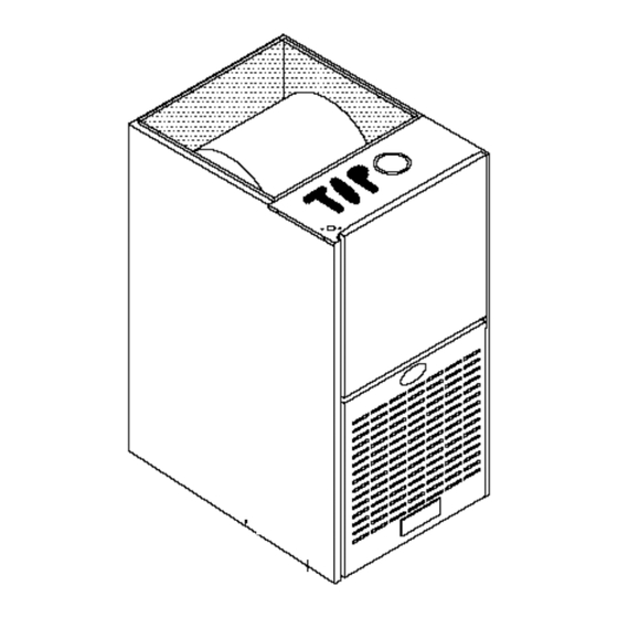
Downflow Only
Series
SAFETY
CONSIDERATIONS
/k
Recognize safety information.
This is the safety-alert
symbol _.
When you see this symbol on the furnace and in instructions
or
manuals, be alert to the potential for personal injury.
UnderstandthesignalwordDANGER,
WARNING, orCAUTION.
Thesewordeareusedwiththesafety-alertsymbol.
DANGERidenti-
ties the most serious hazards will result in severe personal injury or death. WARNING signifies a hazard that could result in personal
injury or death. CAUT__Nisusedt_identifyunsafepracticeswhichw_u_dresu_tinmin_rpers_na_injury_rpr_ductandpr_pertydam-
age.
Installing and servicing heating equipment can be hazardous due to gas and electrical components.
Only trained and qualified person-
nel should install, repair, or service heating equipment.
Untrained service personnel can perform basic maintenance functions such as cleaning and replacing air filters. All other operations
must be performed by trained service personnel.
When working on heating equipment,
observe precautions in the literature, on tags,
and on labels attached to or shipped with the unit and other safety precautions that may apply.
Follow all safety codes. In the United States, follow all safety codes including the current edition National Fuel Gas Code (NFGC) NFPA
No. 54/ANSIZ223.1.
In Canada, refer to the current edition of the National Standard Canada CAN/CGA-Bt
49.1 - and .2-M91 Natural
Gas and Propane Installation Codes (NSCNGPIC).
Wear safety glasses and work gloves. Havefire extinguisher available during start-
up and adjustment
procedures and service calls.
These instructions
cover minimum requirements
and conform to existing national standards and safety codes.
In some instances,
these instructions exceed certain local codes and ordinances,
especially those that may not have kept up with changing residential
construction
practices.
We require these instructions as a minimum for a safe installation.
Table of Contents
1. Installation...............................
2
2. Combustion & Ventilation Air .................
4
3. GasVent Installation .......................
6
4. Horizontal . ...............................
7
5. GasSupplyand Piping ......................
8
6. ElectricalWiring ........................
7. Ductworkand Filter ......................
8. Checksand Adjustments..................
9. FurnaceMaintenance ....................
11
12
15
16
Design Certified
byAGA
Manufactured
by:
Inter-
City Products
Corporation
(USA)
Lewisburg,
TN USA 37091
This furnace is not designed for use in mobile
homes, trailers or recreational vehicles. Such
use could result in property damage, bodily in-
jury and/or death.
LP3
4/14/97
441 01 2201 02
Advertisement

Related Manuals for ICP NDN5050BFA1


Summary of Contents for ICP NDN5050BFA1
-
Page 1: Table Of Contents
NDN5/GDJ Downflow Only Series SAFETY CONSIDERATIONS Recognize safety information. This is the safety-alert symbol _. When you see this symbol on the furnace and in instructions manuals, be alert to the potential for personal injury. UnderstandthesignalwordDANGER, WARNING, orCAUTION. Thesewordeareusedwiththesafety-alertsymbol. DANGERidenti- ties the most serious hazards will result in severe personal injury or death. -
Page 2: Installation
1. Installation Installation or repairs made unqualified Poison carbon monoxide gas hazard. persons can result in hazards to you and others. this furnace replacing previously Installation MUST conform with local codes or, in common-vented furnace, it may be necessary to the absence of local codes, with codes of the resize the existing vent line and chimney country having jurisdiction. - Page 3 Figure 2 Dimensions and Clearances RECOMMENDED CLEARANCES COMBUSTIBLE MATERIALS FOR ALL UNITS REAR FRONT 3" (75mm) Single Wall Vent 6" (150mm) Type B-1 Double Wall Vent 3" (75mm) For Service 30" (760mm) ALL SIDES OF 1" (25mm) SUPPLY PLENUM SIDES VENT Single Wall Vent 6"...
-
Page 4: Combustion& Ventilationair
2. Combustion& VentilationAir • Carbon tetrachloride. • Halogen type refrigerants. Poison carbon monoxide gas hazard. • Cleaning solvents (such as perchloroethylene). methods described here provide • Printing inks, paint removers, varnishes, etc.. combustion and ventilation air. • Hydrochloric acid. Failure to provide adequate combustion and •... - Page 5 Figure Outside Air (This is ONLY a guide. Subject to codes of country having jurisdiction.) ThisinstallationNOTapprovedin Canada Gas Vent Gas Vent . GableVent) Outlet Outlel Air (1) Air (2', Soft, Vent Furnace Inlet fatal Inlet ieat_ Air(1 Air (2 GableVent Gas Vent VentilatedAttic_ Top Above Insulatio_h_=...
-
Page 6: Gasvent Installation
least 1 square i nch (25mm 2 )offree area per4,000 BTUH oftotal Doors and openable windows are weather stripped and input r ating f orallgasappliances inarea. Other openings are caulked or sealed. These include joints Inunconfined spaces, infiltration should beadequate toprovide around window and door frames, between sole plates and airforcombustion, ventilation and dilution offlue gases. - Page 7 Follow the lighting instructions for each appliance being in- Venting to Existing MasonryChimney spected. Adjust thermostat so appliance(s) will operate continuously. NOTE: The tables and notes referred to below are found in the most recent printing of the GAMA venting tables. Allow 5 minutes of main burner operation, then check for spillage at the draft hood relief opening of each appliance.
-
Page 8: Gassupplyand Piping
Themaximum v ent l ength, regardless ofpipe diameter, is The venting system shall terminate at least 4' (1220mm) 30'(10m) plus amaximum o fuptothree(3) 90 °long radius below, 4' (1220mm) horizontally from, or 1, (300mm) above or"sweep" elbows. I ffewer t han three elbows a reused, any door, window, or gravity air inlet into any building. - Page 9 These units may be used at full input rating when installed at alti- Example tudes up to 2000'. When installed above 2000', the input must be Natural Gas No. of Seconds Time Per Cubic BTU Per decreased 4% for each 1000' above sea level. This may be ac- BTU Content Per Hour Foot in Seconds...
- Page 10 PROPANE MEAN ELEVATION FEET ABOVE SEA LEVEL HEATING VALUE 0 to 2000 to 3000 to 4000 to 5000 to 6000 to 7000 to BTU/CU. FT. 1999 2999 3999 4999 5999 6999 8000 2500 10.0" wc 10.0" wc 9.4" wc 10.0" wc 9.8"...
-
Page 11: Electricalwiring
• During pressure testing of gas piping system, observe the following: Fire or explosion hazard. a. If test pressure does not exceed 1/2 PSIG, isolate the furnace by closing its individual manual shutoff valve. Gas connector must be properly installed, cannot go through the side of the furnace, and can not be b. -
Page 12: Ductworkand Filter
Figure 9 Electrical Connections 115V, 60Hz NEUT. Connection _round Thermostat Low Voltage Terminal Board 25-21-05a 7. Ductworkand Filter Subbase for Combustible Floors - Furnace Only since the base is equipped with locating tabs that center the base over the opening. The Subbase for Combustible Floors MUST be used when a downflow furnace is set on combustible... - Page 13 Set the base over the opening in the floor, centering the Figure 11 Exploded View of Base for opening in the base over the opening in the floor. Fasten the Downflow Cased Coil base to the floor with screws or nails. See Figure 10 and Figure 12.
-
Page 14: Checksand Adjustments
Insert end of filter rack (19ram) flange into slot in with 3/4" Figure 14 Filter Rack Installation the back of the unit. See Figure 15. With filter rack pushed back, insert front end with 1/4" (6ram) flange into position and push into front slot. with filter rack pushed as far forward as it will go, bend 1/4"(6mm) flange and 3/4"(19mm) flange up 90 degrees. - Page 15 Figure 17 Main Burner Fire or explosion hazard. Turn OFF gas at shut off before connecting U-tube Burner Face manometer. Failure to turn OFF gas at shut off before connecting U-tube manometer can result in personal injury and/or death. With gas OFF, Connect U-Tube manometer to tapped 10-10-78 opening on gas valve.
-
Page 16: Furnacemaintenance
Continuous Fan Operation Blower Speed Chart A terminal is provided on the electronic fan control located in the Wire Color Motor Speed circulating blower compartment for operation of the continuous Black High fan option. This connection is intended for the low speed motor Orange* Med-High tap, and has a lower contact rating (8 amps) than the heat and...
Need help?
Do you have a question about the NDN5050BFA1 and is the answer not in the manual?
Questions and answers