ICP A Series Installation Instructions Manual

ICP A Series Installation Instructions Manual

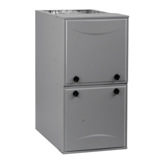
Single-stage, 35-in. (889 mm) tall high efficiency condensing gas furnace

Advertisement

INSTALLATION INSTRUCTIONS
High Efficiency Condensing Gas Furnace
NOTE: Read the entire instruction manual before starting the installation.
SECTIONS
INTRODUCTION
. . . . . . . . . . . . . . . . . . . . . . . . . . . . . . . . . . .
ACCESSORIES
. . . . . . . . . . . . . . . . . . . . . . . . . . . . . . . . . . . . .
LOCATION
. . . . . . . . . . . . . . . . . . . . . . . . . . . . . . . . . . . . . . . .
. . . . . . . . . . . . . . . . . . . . . . . . . . . . . . .
. . . . . . . . . . . . . . . . . . . . . . . . . . . . .
. . . . . . . . . . . . . . . . . . . . . . . . . . . . . . . . . . .
. . . . . . . . . . . . . . . . . . . . . . . . . . . . . . . . . . . . . . .
. . . . . . . . . . . . . . . . . . . . . . . . . . . . . . . . . . . . . .
. . . . . . . . . . . . . . . . . . . . . . . . . . . . . . . . . . . . . . . .
PARTS REPLACEMENT GUIDE
Use of the AHRI Certified TM Mark indicates a
manufacturer's participation in the program.
For verification of certification for individual
products, go to www.ahridirectory.org .
Portions of the text and tables are reprinted from current edition of
NFPA 54/ANSI Z223.1, with permission of National Fire
Protection Association, Quincy, MA 02269 and American Gas
Association, Washington DC 20001. This reprinted material is not
the complete and official position of the NFPA or ANSI on the
referenced subject, which is represented only by the standard in its
entirety.
.
Single- -Stage, 35- -in. (889 mm) Tall
. . . . . . . . . . . . . . . . . . . . . . . . .
. . . . . . . . . . . . . . . . . . . . . . . . . . .
. . . . . . . . . .
. . . . . . . . . . . . . . . . . . . . . . .
. . . . . .
. . . . . . . .
. . . . . . . . . . . . . . . . . . . . . . . .
. . . . . . . . . . . . . . . . . . . . . .
N92ESN
(Series A)
4
5
6
. . .
7
Opening Dimensions
7
Filter Size Information
7
Air Delivery CFM
8
11
. . . . . . . . . . . . . . . . . . . . . . . . . . . . . . . . . . . . . .
14
16
Deductions from Maximum Equivalent Vent Length
23
Maximum Allowable Exposed Vent Lengths Insulation
25
Hangar Spacing
. . . . . . . . . . . . . . . . . . . . . . . . . . . . . . . . . . . . .
26
Combustion- -Air Vent Pipe, Fitting & Cement Material..
31
53
Blower Off Delay Setup Switch
61
71
. . . . . . . . . . . . . . . . . . . . . . . . . . . . . . . . . . . . . . . . . .
73
TABLES
. . . . . . . . . . . . . . . . . . . . . . . . . . . . . . . . . . . . .
. . . . . . . . . . . . . . . . . . . . . . . . . .
. . . . . . . . . . . . . . . . . . . . . . . . . . . . . .
. . . . . . . . . . . . . . . . . . . . . . . . . . . . . . . .
. . . . . . . . . . . . . . . . . . . . . . . . . . . . . . .
. . . . . . . . . . . . . . . . . . . . . . . . . . . . . . . . . . .
. . . . . . . . . . . . . . . . . . . . . . . . . . .
. . . . . . . . . . . . . . . . . . . . . .
. . . . . . . . . . . . . . . . . . . .
. . . . . . . . . . . . . . . . . . . . . . . .
. . . . . . . . . . . . . . . . . . . . .
440 01 4542 00
6
. . . . . . . . . . . . .
5
9
9
19
20
24
25
27
. . . . . . .
34
43
. . . . . . . .
43
. . . . . .
47
49
. . . . .
51
54
56
58
61
11/18/19

Advertisement

Table of Contents
loading
Need help?

Need help?

Do you have a question about the A Series and is the answer not in the manual?

Questions and answers

Subscribe to Our Youtube Channel

Summary of Contents for ICP A Series

  • Page 1: Table Of Contents

    INSTALLATION INSTRUCTIONS Single- -Stage, 35- -in. (889 mm) Tall High Efficiency Condensing Gas Furnace N92ESN (Series A) NOTE: Read the entire instruction manual before starting the installation. SECTIONS TABLES Loose Parts Bag ........SAFETY CONSIDERATIONS .
  • Page 2 Required Notice for Massachusetts Installations IMPORTANT The Commonwealth of Massachusetts requires compliance with regulation 248 CMR as follows: 5.08: Modifications to NFPA- -54, Chapter 10 2) Revise 10.8.3 by adding the following additional requirements: a. For all side wall horizontally vented gas fueled equipment installed in every dwelling, building or structure used in whole or in part for residential purposes, including those owned or operated by the Commonwealth and where the side wall exhaust vent termination is less than seven (7) feet above finished grade in the area of the venting, including but not limited to decks and porches, the following requirements shall be satisfied:...
  • Page 3 A180203 SHIP WT. FURNACE SIZE BOTTOM INLET LB (KG) CABINET WIDTH OUTLET WIDTH AIR INTAKE WIDTH 0401410 14--- 3/16 (361) 12--- 1/2 (319) 12--- 9/16 (322) 7--- 1/8 (181) 112.0 (50.8) 0401712 17--- 1/2 (445) 15--- 7/8 (403) 16 (406) 8--- 3/4 (222) 122.5 (55.6) 0601412...
  • Page 4: Safety Considerations

    SAFETY CONSIDERATIONS as cleaning and replacing air filters. All other operations must be performed by trained service personnel. When working on heating WARNING equipment, observe precautions in literature, on tags, and on labels attached to or shipped with furnace and other safety precautions that may apply.
  • Page 5: Minimum Clearances To Combustible Materials

    10. These Multipoise Gas- -Fired Furnaces are CSA design- -cer- This 4- -way multipoise Category IV condensing furnace is CSA design- -certified as a direct- -vent (2-pipe) or non-direct vent tified for use with natural and propane gases (see furnace (1-pipe) furnace.
  • Page 6: Codes And Standards

    Table 2 – Loose Parts Bag WARNING DESCRIPTION QUANTITY Outlet Restrictor Plate (provided with 40K BTUH FIRE, INJURY OR DEATH HAZARD furnaces only; see Note) Air Intake Pipe Flange Failure to follow this warning could result in personal injury, Vent Pipe Flange death and/or property damage.
  • Page 7: Electrostatic Discharge (Esd) Precautions

    ELECTROSTATIC DISCHARGE (ESD) CAUTION PRECAUTIONS PROCEDURE CAUTION PERSONAL INJURY AND/OR PROPERTY DAMAGE HAZARD Improper use or installation of this furnace may result in FURNACE RELIABILITY HAZARD premature furnace component failure. Unless otherwise Failure to follow this caution may result in unit component prohibited, this gas furnace may be used for heating damage.
  • Page 8: Air For Combustion And Ventilation

    The following types of furnace installations may require Ventilated Combustion Air Applications OUTDOOR AIR for combustion due to chemical exposures: When the furnace is installed using the ventilated combustion air S Commercial buildings option, the attic or crawlspace must freely communicate with the outdoor to provide sufficient air for combustion.
  • Page 9: Minimum Free Area Required

    Table 3 – Minimum Free Area Required for Each Combustion Air Opening or Duct to Outdoors TWO OPENINGS OR TWO HORIZONTAL DUCTS SINGLE DUCT OR OPENING VERTICAL DUCTS (1 SQ. IN./2,000 BTUH) (1 SQ. IN./3,000 BTUH) (1 SQ. IN./4,000 BTUH) (1,100 SQ.
  • Page 10 Outdoor Combustion Air Method Table 4 - - Minimum Space Volumes were determined by using the following equations from the current edition of the National Fuel 1. Provide the space with sufficient air for proper combustion, Gas Code ANSI Z223.1/NFPA 54, 9.3.2.2: ventilation, and dilution of flue gases using permanent hori- 1.
  • Page 11: Condensate Trap

    c. Minimum size of Outdoor openings shall be the size re- quired in Outdoor Combustion Air Method above multi- plied by reduction Factor in b. above. The minimum di- mension of air openings shall be not less than 3 in. (80 mm). CONDENSATE TRAP Condensate Trap - - Upflow Orientation When the furnace is installed in the upflow position, it is not...
  • Page 12 Ä Ä Ä Ä Ä Ä Ä Ä Ä Ä Evaporator Coil + + + Ä Ä Ä Ä Ä Ä Ä Ä Ä Ä Ä Ä Ä Ä Ä Ä Ä Ä Ä Ä 3/4” PVC Ä Ä Ä Ä Ä Ä Ä Ä Ä Ä Ä...
  • Page 13 Evaporator Coil + + + + = Positive pressure < + = Pressure lower than areas with + − = Negative pressure Condensing Furnace Blower creates positive pressure. Positive pressure extends into coil condensate drain (no trap). < + < + <...
  • Page 14: Condensate Drain

    CONDENSATE DRAIN CONNECTION 5. Pull the grommet through the casing from the outside until it is seated in the knockout CAUTION 6. Attach the plain end of the drain elbow to the outlet stub on the drain trap. Secure the drain elbow to the trap with the spring clamp.
  • Page 15 9. Connect additional condensate piping to a code- -approved 8. From inside the casing, insert the short end of the formed drain, or to a condensate pump approved for use with acidic grommet cut from the rubber drain elbow through the furnace condensate and compatible with mineral and 7/8-in.
  • Page 16 Horizontal Orientation Refer to the Specification sheet for the current accessory transition part number. 1. The condensate trap outlet extends 2- -in. (51 mm) below the furnace casing. Leave enough clearance between the furnace CAUTION and the furnace platform for the trap. 2.
  • Page 17 A13109 Fig. 23 - - Horizontal Return Air Configurations and Restrictions Representative drawing only, some models may vary. A10493 Fig. 20 - - Duct Flanges BOTTOM CLOSURE SCREWS (2) Representative drawing only, some models may vary in appearance. Lay furnace on the back or side Remove the two (2) screws that secure the bottom closure panel to the furnace casing and remove the panel...
  • Page 18 4. Install special base coil assembly or coil box as shown in in CAUTION Fig. 25. NOTE: It is recommended that the perforated supply- -air duct MINOR PROPERTY HAZARD flanges be completely removed from furnace when installing the Failure to follow this caution may result in minor property furnace on a factory- -supplied cased coil or coil box.
  • Page 19 Table 5 – Opening Dimensions - - In. (mm) FURNACE PLENUM OPENING FLOOR OPENING CASING APPLICATION WIDTH IN. (mm) Upflow Applications on Combustible or Noncombustible 12--- 11/16 21--- 5/8 13--- 5/16 22--- 1/4 Flooring (Subbase not required) (322) (549) (338) (565) Downflow Applications on Noncombustible Flooring 12--- 9/16...
  • Page 20 Fig. 23. If both side and bottom openings are used in Fig. 23, each Design the filter and associated ductwork for the best match of pressure drop versus filter size. Best practice usually chooses filter opening used will require a filter. systems with pressure drops under 0.2 in.
  • Page 21 Table 7 – Filter Media Pressure Drop (Clean) Versus Face Velocity- - In. W.C. (Pa) Representative After-Market Filter Media* Factory-Accessory Face Velocity Washable Fiberglass* Pleated* (m/s) (1-in. / 2.5 cm) (1-in. / 2.5 cm) (2-in. / 5 cm) (1-in. / 2.5 cm) (2-in.
  • Page 22 COMBUSTION - AIR PIPE (SEE VENTING SECTION) 30 IN. (762 mm) MIN. WORK AREA 2-IN. (51 mm) ROLLOUT PROTECTION REQUIRED Install 12” x 22” (305x559 mm) sheet metal in front of burner compartment area. The sheet metal MUST extend underneath the furnace casing by 1-in. (25 mm) with the door removed.
  • Page 23: Air Ducts

    Leveling Legs (If Desired) The bottom closure panel on furnaces of widths 17- -1/2- -in. (445 mm) and larger may be used for flame roll- -out protection when In upflow position with side return inlet(s), leveling legs may be bottom of furnace is used for return air connection. See Fig. 26 for used.
  • Page 24 Table 9 – Air Delivery - - CFM (With Filter) EXTERNAL STATIC PRESSURE (IN.W.C.) FURNACE SPEED Function SIZE TAPS 0.10 0.20 0.30 0.40 0.50 0.60 0.70 0.80 0.90 1.00 Gray Cooling. Do not use for heating 1120 1085 1055 1015 Yellow Cooling.
  • Page 25: Gas Piping

    GAS PIPING 1 1/2 inch for Gas WARNING FIRE OR EXPLOSION HAZARD 7/8 inch for 115 VAC Electric Failure to follow this warning could result in personal injury, death, and/or property damage. Never purge a gas line into a combustion chamber. Never test for gas leaks with an open flame.
  • Page 26: Electrical Connections

    ELECTRICAL CONNECTIONS WARNING WARNING FIRE OR EXPLOSION HAZARD ELECTRICAL SHOCK, FIRE OR EXPLOSION A failure to follow this warning could result in personal HAZARD injury, death, and/or property damage. If local codes allow the use of a flexible gas appliance Failure to follow safety warnings could result in connector, always use a new listed connector.
  • Page 27: Electrical Data

    A190079 Fig. 32 - - Typical Single- -Stage Wiring Diagram Table 11 – Electrical Data MAXIMU OPERATING VOLTAGE MINIMUM VOLTS--- MAXIMUM MAXIMUM RANGE* UNIT WIRE FURNACE SIZE HERTZ--- UNIT WIRE FUSE OR CKT AMPACITY# SIZE PHASE AMPS LENGTH BKR AMPS Maximum* Minimum* FT (M)}...
  • Page 28 A190279 Fig. 33 - - Field- -Supplied External Electrical Box on Furnace Casing J- -Box Installation WARNING FIRE OR ELECTRICAL SHOCK HAZARD Failure to follow this warning could result in personal injury, death, or property damage. High voltage field connections must be located in J- -Box with furnace, or in field supplied external disconnect mounted to furnace.
  • Page 29 For a side- -mounted external electrical box, complete the BX Cable Installation in Furnace J- - Box following: 1. Install J- -Box mounting bracket to inside of furnace casing. 1. Align the J- -Box bracket with the knock- -out inside the See Fig.
  • Page 30 A190022 Fig. 36 - - Example of Single Stage Furnace Control A11157 Fig. 37 - - Field- -supplied Isolation Relay for Humidifiers with Internal Power Supply Specifications subject to change without notice. 440 01 4542 00...
  • Page 31 2. Outdoor Air Temperature Sensor must be attached in all dual fuel application. 3. Refer to ICP thermostat Installation Instructions for additional information and setup procedure. 4. When using a Humidity Sensing Thermostat, set DEHUMIDIFY OPTIONS to H DE--ENRGZD FOR DEHUM 5.
  • Page 32 consulted before installation to determine the need to obtain a WARNING permit. *IPEX System 636™ is a trademark of IPEX Inc. WARNING CARBON MONOXIDE POISONING HAZARD Failure to follow the steps outlined below for each appliance connected to the venting system being placed into operation CARBON MONOXIDE POISONING HAZARD could result in carbon monoxide poisoning or death.
  • Page 33 the vent or liner manufacturer’s installation instructions. Care must All air for combustion is piped directly to the furnace from a space be taken to prevent the exhaust gases from one appliance from that is well ventilated with outdoor air (such as an attic or crawl contaminating the combustion air of other gas appliances.
  • Page 34: Vent Termination Kit For Direct Vent (2- -Pipe) System

    A13305 Fig. 39 - - Combustion Air and Vent Pipe Termination for Direct Vent (2- -Pipe) System A05091 Fig. 40 - - Vent Pipe Termination for Non- -Direct Vent and Ventilated Combustion Air System Table 12 – Vent Termination Kit for Direct Vent (2- -pipe) Systems Approved Two---Pipe Termination Fittings Vent and Allowable...
  • Page 35 Locating the Vent Termination required by National code authorities. Allowable vent and combustion air terminations are shown in Fig. 39. General WARNING NOTE: Termination Requirements for the Provinces of Alberta and Saskatchewan are located at the end of this section. CARBON MONOXIDE POISONING HAZARD Combustion- -air inlet pipe (direct vent/2- -pipe system only) and Failure to follow the instructions outlined below for each...
  • Page 36 A12326 Fig. 43 - - Direct Vent Termination Clearance NOTE: The following is based upon National codes for gas appliances and is provided as a reference. Refer to local codes which may supersede these standards and/or recommendations. (1 ) (2 ) Canadian Installations U.S.
  • Page 37 A12325 Fig. 44 - - Ventilated Combustion Air and Non- -Direct Vent Termination Clearance NOTE: The following is based upon National codes for gas appliances and is provided as a reference. Refer to local codes which may supersede these standards and/or recommendations. (1 ) (2 ) Canadian Installations...
  • Page 38 A190032 Fig. 45 - - Inside Corner Termination Inside Corner Terminations Inside corner vent terminations are permitted provided that: S Only two exterior walls come together to form an angle of 90 degrees to 135 degrees. There are no other exterior walls attached to either wall to form an alcove.
  • Page 39 Termination Requirements for the Provinces of Alberta and Saskatchewan The Provinces of Alberta and Saskatchewan require a minimum unobstructed distance of 4 ft. (1.2 M) from the foundation to the property line of the adjacent lot for vent termination of any appliance with an input over 35,000 btuh.
  • Page 40 A10497 Fig. 47 - - Vent Terminations for Ventilated Combustion Air NOTICE OPTIONAL CONFIGURATION FOR COMBUSTION FURNACE AIR INLET PIPE In applications where there is a risk of excessive moisture entering the combustion air inlet pipe, a moisture trap may be added to the inlet pipe to help prevent moisture from entering the furnace from the combustion air inlet pipe.
  • Page 41 Recommended Combustion Air Inlet Moisture Trap Recommended to prevent moisture from trickling into the furnace vestibule, a trap can be installed in the intake air pipe near the furnace. To prevent moisture, connecting a drain line to the trap is recommended as trace amounts of moisture will evaporate into the intake air stream.
  • Page 42 TO CODE- - APPROVED DRAIN OR CONDENSATE PUMP Recommend “T” fitting with 4--inch minimum height standpipe (A) of same diameter or larger extending upward. Dry Well Dry Well (water tight Dry Well and removable) (water tight (water tight and removable) and removable) Representative drawing only, some models may vary in appearance.
  • Page 43: Maximum Equivalent Vent Length

    Table 13 – Maximum Equivalent Vent Length NOTE: Maximum Equivalent Vent Length (MEVL) includes standard and concentric vent termination and does NOT include elbows. Use Table 14 - Deductions from Maximum Equivalent Vent Length to determine allowable vent length for each application. Single Stage 92% --- Ft.
  • Page 44 Combustion Air and Vent Piping Insulation NOTE: Pipe length (ft. / M) specified for maximum pipe lengths located in unconditioned spaces cannot exceed total allowable pipe Guidelines length as calculated from Table 13. NOTE: Use closed cell, neoprene insulation or equivalent. Configure the Furnace The vent pipe may pass through unconditioned areas.
  • Page 45 Rotate vent elbow to required position. Any other unused knockout may be used for combustion air connection. Rotate vent elbow to required position. & UPFLOW LEFT CONFIGURATION A11309A DOWNFLOW LEFT CONFIGURATION A11311A Rotate vent elbow to required position. Any other unused knockout may be used Any other unused for combustion air...
  • Page 46 ALTERNATE COMBUSTION AIR CONNECTIONS HORIZONTAL RIGHT ---VERTICAL VENT CONFIGURATION A11337 HORIZONTAL LEFT ---VERTICAL VENT CONFIGURATION A11327A Alternate combustion air connection. Rotate vent elbow to required position. Vent Pipe Requires Internal Vent Kit See Product Data for Current Kit Number HORIZONTAL RIGHT ---LEFT VENT CONFIGURATION HORIZONAL LEFT ---LEFT VENT CONFIGURATION A11336 A11328A...
  • Page 47 Table 15 – Maximum Allowable Exposed Vent Lengths in Unconditioned Space Table - - Ft. Unit Size 40,000* BTUH 60,000 BTUH Uninsulated 3/8-in. Insulation 1/2-in. Insulation Uninsulated 3/8-in. Insulation 1/2-in. Insulation Pipe Dia. 1 ½ 2 ½ 1 ½ 2 ½ 1 ½...
  • Page 48 A13074 Fig. 57 - - Vent Coupling and Adapter with Gaskets Near Furnace Vent Connections WARNING Offsets in the vertical portion of the vent pipe should be made with 45 deg. elbows instead of 90 deg. elbows. Short horizontal runs of vent pipe are difficult to pitch correctly and may trap water in the CARBON MONOXIDE POISONING HAZARD vent pipe.
  • Page 49 11. Seal around the combustion air pipe with silicone or foil CAUTION tape. SILICONE SEALERS MAY NOT BE APPRO- PRIATE FOR POLYPROPYLENE VENT SYSTEMS. SEE POLYPROPYLENE VENT SYSTEM MANU- FURNACE RELIABILITY HAZARD FACTURER’S INSTRUCTIONS. Failure to follow this caution may result in nuisance short 12.
  • Page 50 5. Re- -insert the pipe through the casing into the vent elbow. Termination elbows will be installed after the vent and (if used) 6. Tighten the clamp around the outlet of the vent elbow. combustion air pipe is installed. Torque the clamp to 15 lb- -in. NOTICE 7.
  • Page 51 Inducer Outlet Restrictor To determine if the outlet restrictor is required, see Table 13. Failure to use an outlet restrictor on the 40K input model when To improve efficiency and operation of 40K, 60K, 100K or 120K required may result in flame disturbance or flame sense BTUH input models on very short vent systems, an inducer outlet lockout.
  • Page 52: Venting

    Venting System Length Calculations The Total Equivalent Vent Length (TEVL) for EACH combustion air or vent pipe equals the length of the venting system, plus the equivalent length of elbows used in the venting system from Table 14. Standard vent terminations or factory accessory concentric vent terminations count for zero deduction. See vent system manufacturer’s data for equivalent lengths of flexible vent pipe or other termination systems.
  • Page 53: Start- -Up, Adjustment, And Safety Check

    START- - UP, ADJUSTMENT, AND SAFETY Prime Condensate Trap with Water CHECK WARNING NOTICE CARBON MONOXIDE POISONING HAZARD Failure to follow these warnings could result in personal injury Important Installation and Start- -up Procedures or death. Failure to follow this procedure may result in a nuisance Failure to use a properly configured trap or NOT smoke or odor complaint.
  • Page 54: Altitude Derate Multiplier For U.s.a

    NOTICE WARNING FIRE OR EXPLOSION HAZARD The NATURAL GAS manifold pressure adjustments in Table 20 compensate for BOTH altitude AND gas heating value. Failure to follow this warning could result in personal DO NOT apply an additional de- -rate factor to the pressures injury, death, and/or property damage.
  • Page 55 d. Connect a water column manometer or similar device to NOTICE manifold pressure tap. e. Turn gas valve ON/OFF switch to ON. f. Manually close blower door switch. If orifice hole appears damaged or it is suspected to have been g.
  • Page 56 j. Remove jumper R to W. 2. When thermometer readings stabilize, subtract return- -air 2. Verify natural gas input rate by clocking meter. temperature from supply- -air temperature to determine temperature rise. NOTE: Contact your HVAC distributor or gas supplier for metric If the temperature rise is outside this range, check the following: gas meter Tables, if required.
  • Page 57 (cooling blower tap). Use the provided wire ties to secure the loose Check Safety Controls blower motor speed lead and any other loose wires, being careful The flame sensor, gas valve, and pressure switch were all checked not to put tension on any wire connectors. in the Start- -up procedure section as part of normal operation.
  • Page 58 Table 20 – Orifice Size and Manifold Pressure (in. w.c.) for Gas Input Rate SINGLE-STAGE FURNACE (TABULATED DATA BASED ON 20,000 BTUH PER BURNER, DERATED 2%/1000 FT (305M) ABOVE SEA LEVEL) ALTITUDE RANGE HEAT VALUE 0.58 0.60 0.62 0.64 AT ALTITUDE Orifice Manifold Orifice...
  • Page 59: Orifice Size And Manifold Pressure

    Table 20 - - Orifice Size and Manifold Pressure (in. w.c.) for Gas Input Rate (Cont.) SINGLE-STAGE FURNACE (TABULATED DATA BASED ON 20,000 BTUH PER BURNER, DERATED 2%/1000 FT (305M) ABOVE SEA LEVEL) ALTITUDE RANGE HEAT VALUE 0.58 0.60 0.62 0.64 Orifice Manifold...
  • Page 60 A190035 Fig. 65 - - Service Label Information Specifications subject to change without notice. 440 01 4542 00...
  • Page 61: Service And Maintenance Procedures

    Table 21 – Gas Rate (CU ft./hr) CAUTION SIZE OF TEST DIAL SIZE OF TEST DIAL SEC. SEC. ENVIRONMENTAL HAZARD REV. REV. Failure to follow this caution may result in environmental 1800 pollution. 1636 1500 Remove and recycle all components or materials (i.e. oil, 1385 refrigerant, control board, etc.) before unit final disposal.
  • Page 62 The electrical ground and polarity for 115- -v wiring must be To Begin Component Self-Test: properly maintained. Refer to Fig. 32 for field wiring information 1. Remove blower access door. and to Fig. 72 for furnace wiring information. 2. Disconnect the thermostat R lead from furnace control. 3.
  • Page 63 10. Attach entire literature packet to furnace. 5. Inspect the vent pipe/vent system before each heating sea- son for water leakage, sagging pipes or broken fittings. Care and Maintenance Have vent pipes/vent system serviced by a qualified service WARNING agency. 6.
  • Page 64 3. All factory wires can be left connected, but field thermostat WARNING and accessory wiring may need to be disconnected depend- ing on their length and routing. 4. If the vent and combustion air pipe passes through the ELECTRICAL OPERATION HAZARD blower compartment, it will be necessary to remove the Failure to follow this warning could result in personal injury pipes from the blower compartment.
  • Page 65 Cleaning Burners and Flame Sensor 18. Check ignitor resistance. Nominal resistance is 40 to 70 ohms at room temperature and is stable over the life of the The following items must be performed by a qualified service ignitor. technician. If the burners develop an accumulation of light dirt or 19.
  • Page 66 a. Using an ohm meter, check resistance across both ignitor 3. Disconnect pressure switch tube from pressure switch port. leads in connector. NOTE: Ensure the pressure switch tube disconnected from the b. Cold reading should be between 40 ohms and 70 ohms. pressure switch is higher than the collector box opening or water will flow out of tube.
  • Page 67 11. Run the furnace through two complete heating cycles to 5. Remove two screws attaching top filler plate and rotate up- check for proper operation wards to gain access to screws attaching burner assembly to 12. Install control door when complete. cell panel.
  • Page 68 WINTERIZATION 1. Obtain propylene glycol (RV/swimming pool antifreeze or equivalent). CAUTION 2. Turn off gas and electrical supplies to your furnace. 3. Remove furnace control door. 4. Remove the top unused rubber plug from the port on the UNIT AND PROPERTY DAMAGE HAZARD collector box opposite the condensate trap.
  • Page 69 Specifications subject to change without notice. 440 01 4542 00...
  • Page 70 A190092 Fig. 71 - - Troubleshooting Guide Specifications subject to change without notice. 440 01 4542 00...
  • Page 71: Sequence Of Operation

    SEQUENCE OF OPERATION stopping gas flow to the burners, and de- -energizing the hu- midifier terminal HUM. The inducer motor IDM will re- NOTE: Furnace control must be grounded for proper operation or main energized for a 15- -sec post- -purge period. The blow- control will lock out.
  • Page 72 344443- -2 Rev F A190038 Fig. 72 - - Wiring Diagram Specifications subject to change without notice. 440 01 4542 00...
  • Page 73 PARTS REPLACEMENT INFORMATION GUIDE Casing Group Gas Control Group Blower door Burner Bottom plate Flame sensor Control door Gas valve Door knob assembly Hot surface ignitor Top filler plate Manifold Orifice Electrical Group Heat Exchanger Group 3- -Amp fuse Circuit board Containment plate Control box Coupling box...
  • Page 74 Copyright 2019 International Comfort Products Lewisburg, TN 37091 USA Specifications subject to change without notice. 440 01 4542 00...

This manual is also suitable for:

N92esn

Table of Contents