EVGA nForce 780i SLI FTW User Manual
Evga motherboard user's guide
Hide thumbs
Also See for nForce 780i SLI FTW:
- User manual (127 pages) ,
- Quick install manual (2 pages) ,
- User manual (7 pages)
Table of Contents
Advertisement
Advertisement
Table of Contents

Related Manuals for EVGA nForce 780i SLI FTW


Summary of Contents for EVGA nForce 780i SLI FTW
- Page 1 User Guide EVGA force 780i SLI FTW Motherboard...
- Page 2 EVGA...
-
Page 3: Table Of Contents
Before You Begin… ... ix Parts NOT in the Kit ... ix Intentions of the Kit ... ix EVGA nForce 780i SLI FTW Motherboard ... 1 Motherboard Specifications ... 1 Unpacking and Parts Descriptions ... 3 Unpacking ... 3 Equipment ... 3 EVGA nForce 780i SLI FTW Motherboard ... - Page 4 First/Second/Third Boot Device ... 35 Boot Other Device ... 35 Boot Up NumLock Status ... 35 Security Option ... 35 APIC Mode ... 35 MPS Version Control For OS ... 36 Full Screen LOGO Show ... 36 Advanced Chipset Features ... 37 EVGA...
- Page 5 POWER ON Function ... 44 PnP/PCI Configuration Menu ... 45 Init Display First ... 45 Reset Configuration Data ... 45 Resources Controlled By ... 46 IRQ Resources ... 46 PCI/VGA Palette Snoop ... 46 Maximum Payload Size ... 47 EVGA...
- Page 6 CPU Feature ... 57 Limit CPUID MaxVal ... 57 Intel SpedStep ... 57 PPM Mode ... 57 CPU Thermal Control ... 58 C1E Enhanced Halt State ... 58 Execute Disable Bit ... 58 Virtualization Technology ... 58 CPU Core 1-3 ... 58 EVGA...
- Page 7 Load Timing/Voltage Set ... 61 Save Timing/Voltage Set ... 61 Installing Drivers and Software ... 63 Driver Installation ... 63 EVGA Enthusiast Glossary ... 65 Appendix A. POST Codes for EVGA nForce 780i SLI FTW Platform ... 67 NVMM POST Codes ... 73 EVGA...
-
Page 8: List Of Figures
Figure 1. EVGA nForce 780i SLI FTW Motherboard Layout ... 5 Figure 2. Chassis Back Panel Connectors ... 6 Figure 3. Power Supply Connectors ... 12 Figure 4. PWR1 Motherboard Connector ... 13 Figure 5. BIOS CMOS Setup Utility Main Menu ... 27 Figure 6. -
Page 9: Before You Begin
Parts NOT in the Kit This kit contains all the hardware necessary to install and connect your new EVGA force® 780i SLI FTW motherboard. However, it does not contain the following items that must be purchased separately to make the motherboard functional. -
Page 11: Evga Nforce 780I Sli Ftw Motherboard
Thank you for buying the EVGA nFore 780i SLI FTW Motherboard: This motherboard offers the tools and performance PC users’ demand. When combined with two or three SLI- Ready NVIDIA GeForce graphics cards, you get innovative NVIDIA SLI Technology for enhanced system performance. - Page 12 Supports S0 (normal), S1 (power on suspend), S3 (suspend to RAM), S4 (Suspend to disk - depends on OS), and S5 (soft - off) Expansion Slots Two PCI slots One PCI Express x1 slot Three PCI Express x16 Graphics slots EVGA...
-
Page 13: Unpacking And Parts Descriptions
Unpacking The EVGA nForce 780i SLI FTW motherboard comes with all the necessary cables for adding a motherboard to a new chassis. If you are replacing a motherboard, you may not need many of these cables. Be sure to inspect each piece of equipment shipped in the packing box. If anything is missing or damaged, contact your reseller. -
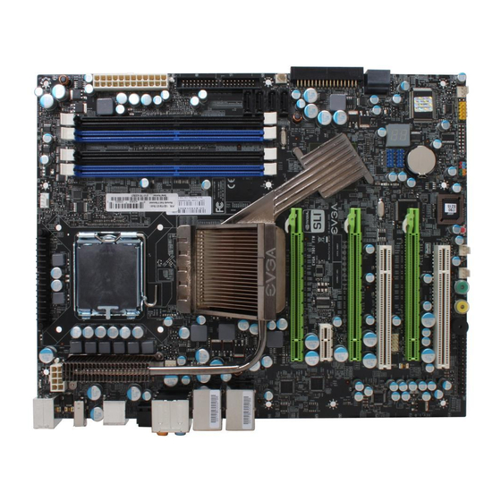
Page 14: Evga Nforce 780I Sli Ftw Motherboard
EVGA nForce 780i SLI FTW Motherboard The EVGA nForce 780i SLI FTW motherboard with the NVIDIA nForce 780i SLI SPP and MCP processor is a PCI Express, SLI-ready motherboard. Figure 1 shows the motherboard and Figures 2 shows the back panel connectors. - Page 15 FDD connector – Floppy Disk Drive Connector NVIDIA MCP (passive heat sink) 10. System Speaker – Provides POST Codes via audio EVGA nForce 780i SLI FTW Motherboard Layout 11. USB headers – for additional USB connectors. 12. Motherboard battery – helps retain system BIOS settings 13.
-
Page 16: Chassis Back Panel Connectors
Black Grey 7. LAN Port with LEDs to indicate status. Yellow/Light Up/Blink = 10 Mbps/Link/Activity Yellow and Green/Light Up/Blink = 100 Mbps/link/Activity Green/Light Up/Blink = 1000 Mbps/Link/Activity EVGA Chassis Back Panel Connectors 4-Channel Line-In Front Speaker Out Mic In Rear Speaker Out... -
Page 17: Hardware Installation
To reduce the risk of fire, electric shock, and injury always follow basic safety precautions. Remember to remove power from your computer by disconnecting the AC main source before removing or installing any equipment from/to the computer chassis. Hardware Installation EVGA... -
Page 18: Preparing The Motherboard
There are many different fan types that can be used with this motherboard. Follow the instructions that came with your fan assembly. Be sure that the fan orientation is correct for your chassis type and your fan assembly. EVGA Align notches with notches on the CPU... -
Page 19: Installing System Memory (Dimms)
DIMM Slot 1 DIMM Slot 1 DIMM Slot 2 DIMM Slot 3 DIMM Slot 3 DIMM Slot 1 DIMM Slot 2 DIMM Slot 3 DIMM Slot 1 DIMM Slot 2 DIMM Slot 3 DIMM Slot 1 DIMM Slot 3 EVGA... -
Page 20: Installing The Motherboard
Align the mounting holes with the studs/spacers. Align the connectors to the I/O shield. Ensure that the fan assembly is aligned with the chassis vents according to the fan assembly instruction. Secure the motherboard with a minimum of eight-to-ten screws. EVGA... -
Page 21: Connecting Cables And Setting Switches
Serial ATA II Chassis Fans Rear panel USB 2.0 Adapter Expansion slots CMOS jumper settings See Figure 1 on page 5 to locate the connectors and jumpers referenced in the following procedure. PWR1 PWR2 EVGA... -
Page 22: Power Supply Connectors
Make sure you have enough power to cover all the expansion cards you will be installing. To determine what power requirements are for your specific configuration or a certified power supply vendor, refer to EVGA 6-pin (3x2) PCI-E connector Power Supply Connectors... -
Page 23: Figure 4. Pwr1 Motherboard Connector
This connector is notched, do not force in. Board edge Figure 4. PWR1 Motherboard Connector Table 1. Connector PWR1 connector Plug power cable from system power supply to PWR1 PWR1 Pin Assignments Signal +3.3V +3.3V PWROK +5V_AUX +12V +12V +3.3V Signal +3.3V -12V PS_ON RSVD EVGA... -
Page 24: 8-Pin Atx 12V Power (Pwr2)
If an ATA-66/100 disk drive and a disk drive using any other IDE transfer protocol are attached to the same cable, the maximum transfer rate between the drives may be reduced to that of the slowest drive. EVGA PWR2... -
Page 25: Connecting Serial Ata Cables
RAID 5, RAID 0+1 and JBOD configurations. SATA 1 (bottom) SATA 2 (top) SATA 3 SATA 4 Connect the locking cable end to the motherboard connector. Connect the end without the lock to the drive. SATA 5 SATA 6 EVGA... -
Page 26: Connecting Internal Headers
Attach the hard disk drive indicator LED cable to these two pins. The HDD indicator LED indicates the activity status of the hard disk drives. RESET Attach the Reset switch cable from the front panel of the case to these two pins. The system restarts when the EVGA switch is pressed. RESET... -
Page 27: Ieee 1394A
IEEE 1394a Connector In/Out Description Hard disk drive LED pulls up to +5V Hard disk drive active LED Front panel green light Front panel yellow light Ground Reset switch Power switch Ground Signal TPA+ TPA- TPB+ TPB- +12V +12V Empty EVGA... -
Page 28: Usb Headers
(not all chassis are equipped with the front panel option). Connect the two ends of the cables to the USB 2.0 headers on the motherboard. Table 4. Connector USB 2.0 Header Connector EVGA USB 2.0 Header Pins Signal 5V_DUAL Empty... -
Page 29: Audio
The audio connector supports HD audio standard and provides two kinds of audio output choices: Front Audio and Rear Audio. The front Audio supports re-tasking function. Table 5. Front Audio Connector Connector Front Audio Connector Signal PORT1_L AUD_GND PORT1_R PRECENCE_J PORT2_R SENSE1_RETURN SENSE_SEND Empty PORT2_L SENSE2_RETURN EVGA... -
Page 30: Fan Connections
PC Health Status CPU Fan Connector SENSE CONTROL Install the fan over the nForce 780i SLI SPP to draw heat from the MCP. The fan plugs into a 3-pin connector. EVGA nForce 780i SLI SPP/MCP fan connector Fan Connector +12V SENSE... -
Page 31: Com1
COM device to the other side of the cable. Auxiliary fan connector Fan Connector +12V SENSE Fan Connector Auxiliary fan +12V connector SENSE System fan Fan Connector connector +12V SENSE EVGA... -
Page 32: Fdd Connector
360K, 720K, 1.2M, 1.44m, and a 2.88M floppy disk drive (FDD). Expansion Slots The EVGA nForce 780i SLI FTW motherboard contains six expansion slots, four PCI Express slots and two PCI slots. PCI Slots The two PCI slots support many expansion cards such as a LAN card, USB card, SCSI card and other cards that comply with PCI specifications. -
Page 33: Pci Express X1 Slot
When installing a PCI Express x16 card, be sure the retention clip snaps and locks the card into place. If the card is not seated properly, it could cause a short across the pins. Secure the card’s metal bracket to the chassis back panel with the screw used to hold the blank cover. EVGA... -
Page 34: Clear Cmos Button
Hard Disk Drive Activity LED which will flicker accordingly. The Green Power button features an integrated power LED and will stay solid for as long as the system is turned on and running. EVGA Onboard Onboard Reset... -
Page 35: Configuring The Bios
This section includes the following information: Enter BIOS Setup Main Menu Standard CMOS Features Advanced BIOS Features Advanced Chipset Features Integrated Peripherals Power Management Setup PnP/PCI Configurations PC Health Status Frequency/Voltage Control EVGA... -
Page 36: Enter Bios Setup
Note that on the BIOS screens all data in changeable, data in red box EVGA key when the following message briefly displays at the bottom of the takes you to the Phoenix-Award BIOS CMOS Setup Utility. keys to scroll through the options or press... -
Page 37: Figure 5. Bios Cmos Setup Utility Main Menu
Use this menu to optimize system performance and configure clocks, voltages, memory timings, and more. Frequency/Voltage Control Load Fail-Safe Default Load Optimized Defaults Set Supervisor Password Set Password Save & Exit Setup Exit Without Saving : Select Item Type.., SLI-Ready memory - Disabled EVGA... -
Page 38: Standard Cmos Features Menu
HDD model, and so on. Use the options or press Enter option you choose. To go back to the previous menu, press EVGA Page Up to display the sub-menu. Use the arrow keys to position the selector in the keys to scroll through the... -
Page 39: Date And Time
Sat, Jul 01 2006 14 : 48: Item Help Main Level Change the day, month, year and century ESC:Exit F1:General Help yellow is changeable, data in Page Up Page EVGA... -
Page 40: Ide Channel And Sata Channel
When you set the channel to enter the number of cylinders, heads, Precomp, landing zone, and sector. You can manually enter the values or you can press values. EVGA to display the IDE/SATA sub-menu. Enter [None] Press ENTER to display... -
Page 41: Drive A
:Move to display the sub- Enter to accept the Enter ENTER:Accept ESC:Abort Press ENTER to display sub-menu ... [ ] ... [ ] ... [ ] ... [ ] ... [ ] ... [ ] ENTER:Accept ESC:Abort EVGA... -
Page 42: Halt On
BIOS determines how much extended memory is present during the POST. Total Memory This value represents the total memory of the system. EVGA keys to scroll through the options or press Page Down sub-menu. Use the arrow keys to position the selector in the option... -
Page 43: Advanced Bios Features
F5: Previous Values F7:Defaults is for information only, data in yellow red box is highlighted for selection. to display the Enter Item Help Main Level Select Removable Boot Device Priority ESC:Exit F1:General Help is changeable, data in blue is non- EVGA... -
Page 44: Removable Device Priority
Enabling this option allows the system to skip certain tests while booting, which reduces the time needed to boot the system. Use the Enable Disable EVGA keys to move the device priority up or down in the list. To go back to – ST3802110A to view available networks. -
Page 45: First/Second/Third Boot Device
CMOS Setup Setup to require a password to access the CMOS Setup screen and when the to display the sub- Enter . Select to activate the NumLock to disable the key. NumLock Page EVGA... -
Page 46: Mps Version Control For Os
Use the options. Full Screen LOGO Show This option allows you to enable or disable the display of the full-screen logo when the system boots. Use the EVGA Page Up Page Down keys to toggle between Page Up... -
Page 47: Advanced Chipset Features
CMOS Setup Utility menu and press Phoenix – AwardBIOS CMOS Setup Utility Advanced Chipset Features [Disabled] [Enabled] +/-/PU/PD:Value F10:Save F5: Previous Values F7:Defaults Disabled , the APIC timer is used. Enter Item Help Main Level ESC:Exit F1:General Help EVGA... -
Page 48: Integrated Peripherals Menu
IEEE1394 controller HD Audio IDE HDD Block Mode Onboard FDC Controller Onboard Serial Port 1 :Move Figure 9. EVGA from the CMOS Setup Utility menu and press Phoenix – AwardBIOS CMOS Setup Utility Integrated Peripherals [Press Enter] [Press Enter] [Press Enter]... -
Page 49: Ide Function Setup
, you can select a mode for the primary Master and Slave PIO. Select Mode 4 through [Enabled] is set to [Auto] [SATA-0] IDE Prefetch mode [Disabled] Auto Auto UDMA Auto UDMA Auto [Enabled] [All Enabled] [Enabled] , you can disable the primary Master [SATA-0+1] [Enable EVGA... -
Page 50: Raid Config
Use this function to enable specific versions of the USB or disable the onchip USB. When the onchip USB is set to Enabled [V1.1] USB Keyboard/Mouse Support Use these function to enable or disable the onchip WSB support of the keyboard and/or mouse. EVGA [Enabled] RAID [Disabled] RAID [Disabled] RAID [Disabled] RAID... -
Page 51: Mac Config
This function on the Integrated Peripherals menu allows you to select the onboard serial port 1 function. Options are [Disabled]. [Enabled] [Disabled] [Enabled] to automatically detect the optimal number of block [Disabled] [3F8/IRQ4] 2E8/IRQ3] [3E8/IRQ4] Auto or disable their if your drive does not [Auto] , and EVGA... -
Page 52: Power Management Setup Menu
ACPI Suspend Type This function on the Power Management Setup menu allows you to select an ACPI Suspend Type. Types to select from are EVGA from the CMOS Setup Utility menu and press Phoenix – AwardBIOS CMOS Setup Utility Power Management Setup [Enabled] [S1&S3]... -
Page 53: Soft-Off By Pbnt
[Delay 4 Sec] [Disable] to prevent power-on by alarm. When set to [Disabled] [ 0] [0 : 0 : 0] Page Up Page Down keys to scroll through numbers or keys. – EVGA... -
Page 54: Power On Function
POWER ON Function KB Power ON Password Hot Key Power On Mouse Left Mouse Right Any Key EVGA KB Power ON Password is selected, the [Password] [Enter] Ctrl-F1 Hot key Power On function is selected, the [Hot key]... -
Page 55: Pnp/Pci Configuration Menu
Extended System Configuration Data (ESCD) when you exit Setup. from the CMOS Setup Utility menu and press Phoenix – AwardBIOS CMOS Setup Utility PnP/PCI Configuration [PCI Slot] [Disabled] [Auto(ESCD)] Press Enter [4096] +/-/PU/PD:Value F10:Save F5: Previous Values F7:Defaults Enter Item Help Main Level ESC:Exit F1:General Help EVGA... -
Page 56: Resources Controlled By
PCI or ISA Bus architecture. PCI/VGA Palette Snoop This function on the PnP/PCI Configuration menu allows you to enable or disable the Palette Snoop function. EVGA if you have installed a new add-on and the system reconfiguration has IRQ Resources is enabled for input. -
Page 57: Maximum Payload Size
0 RPM 0 RPM +/-/PU/PD:Value F10:Save F5: Previous Values F7:Defaults Blue are dynamic and change as the speed and voltages of the keys Page Up Page Down – to display Enter Item Help Main Level ESC:Exit F1:General Help EVGA... -
Page 58: Dynamic Fan Control
To set the fan speed to a constant rate, select [Manual] and then enter the speed from 0% to 100%. Set the desired speed for the AUX, and Chassis fans from 0% to 100%. The system defaults to 100%. EVGA [SmartFan] [SmartFan] [SmartFan] [100]... -
Page 60: Frequency/Voltage Control
CPU’s heat dissipation, O.C memory modules and so on. Phoenix – AwardBIOS CMOS Setup Utility Frequency/Voltage Control [Disabled] [Press Enter] [Press Enter] [Press Enter] [Enabled] [Press Enter] [Press Enter] +/-/PU/PD:Value F10:Save F5: Previous Values F7:Defaults Item Help Main Level ESC:Exit F1:General Help EVGA... -
Page 61: System Clocks
PCIe Spread Spectrum(MCP) SATA Spread Spectrum :Move Figure 13. Note that all data in changeable, and data in a EVGA from the Advanced Chipset Features menu and press Phoenix – AwardBIOS CMOS Setup Utility System Clocks Settings Current Vale 2933.3 2933.3... -
Page 62: Frequency Settings
HT multiplier options and set [1 x] keys to scroll through the HT multiplier options and set [1 x] [5 x]. through [5 x] through EVGA... -
Page 63: Spread Spectrum
Page Up the CPU. Option values are HT Spread Spectrum Disabled PCIe Spread Spectrum(MCP) Disabled SATA Spread Spectrum Disabled EVGA keys to scroll through the Spread Spectrum options for Page Down [Disabled] [UP Spread] [Center Spread]. , and... -
Page 64: Fsb & Memory Config
“CPUOC MAX” realizes the complete optimized memory settings when SLI-Ready memory is installed Optimized memory settings by allowing X% CPU overclocking CPU overclocking may require manual overvolting of the CPU to improve system stability ESC:Exit F1:General Help F7:Defaults EVGA... -
Page 65: Fsb & Memory Clock Mode
MEM (DDR), MHz Use the new value. Note that the effect when the system reboots. EVGA CPUOC x% options, the SLI-Ready Memory keys to scroll through the FSB and Memory Clock Page Down FSB (QDR), MHz 2933.3... -
Page 66: Memory Timing Settings
Auto 6.1uS +/-/PU/PD:Value F10:Save F5: Previous Values F7:Defaults Optimal. keys to select Expert keys to select Item Help Main Level Select [Expert] to enter timings manually ESC:Exit F1:General Help[ Optimal prohibits you . When Expert is selected, all EVGA... - Page 67 1 through 7). same bank (options are 1 through 7). tRAS Command Per Clock (options are 1T and 2T). tRRD 31). tWTR are 1 through 10). tREF EVGA Settings [Expert] [Auto(5)] [Auto(7)] [Auto(7)] [Auto(23)] [Auto(2T)] [Auto(4)] [Auto(28)] [Auto(7)]...
-
Page 68: Cpu Feature
[Disabled] Native mode [Disabled] [Enabled] [Enabled] [Enabled] Enabled [Enabled] [Enabled] [Enabled] +/-/PU/PD:Value F10:Save F5: Previous Values to display Enter Item Help Main Level Set linit CPUID MaxVal to 3, should be “Disabled” for WinXP ESC:Exit F1:General Help F7:Defaults EVGA... -
Page 69: Cpu Thermal Control
When this function is disabled, it forces the XD feature flag to always return to zero (0). Virtualization Technology When this function is enabled, it allows a VMM to utilize the additional hardware capabilities provided by Intel Virtualization Technology. CPU Core 1-3 This function allows you to enable or disable CPU Cores. EVGA... -
Page 70: System Voltage
System Voltages Select System Voltages display the System Voltages menu. Parameters EVGA VDroop control CPU Core CPU FSB Memory nForce SPP nForce MCP HT nForce SPP <-> MCP nForce MCP Auxiliary GTLVREF Lane 0 GTLVREF Lane 1 GTLVREF Lane 2... -
Page 71: Nforce Mcp
NVMEM Memory Test This function defines whether you run the NVIDIA memory testing module during POST. The options are Fast, Medium, Slow, and Disable. EVGA keys to select a voltage (1.20V, 1.30V, 1.40V, 1.50V) or select Page Down to automatically set the voltage. -
Page 72: Load Timing/Voltage Set
Select Profile 2 Select Profile 3 ENTER:Accept :Move Enter ... [ ] ... [ ] ... [ ] ... [ ] ESC:Abort ... [ ] ... [ ] ... [ ] ... [ ] ESC:Abort Save timing/voltage to see the options. EVGA... - Page 73 EVGA...
-
Page 74: Installing Drivers And Software
Vista-capable with both 32-bit and 64-bit. The kit comes with a CD that contains drivers and additional NVIDIA software. The CD that has been shipped with your EVGA motherboard contains the following software and drivers: NVIDIA nForce motherboard drivers ... - Page 75 EVGA...
-
Page 76: Evga Glossary Of Terms
EVGA Glossary of Terms: ACPI - Advanced Configuration and Power Interface AFR – Alternate Frame Rendering APIC - Advanced Programmable Interrupt Controller BIOS - Basic Input Output System CD-ROM - Compact Disc Read-Only Memory CMOS - Complementary Metal-Oxide Semiconductor CPU – Central Processing Unit D-ICE –... - Page 77 SLI - Scalable Link Interface SPD - Serial Presence Detect SPDIF - Sony/Philips Digital Interconnect Format SPP - System Platform Processors TCP/IP - Transmission Control Protocol/Internet Protocol USB - Universal Serial Bus VDroop - V-core Voltage Drop VGA - Video Graphics Array EVGA...
-
Page 78: Award Post Code
This section provides the Award POST Codes (Table 6) and the NVMM POST Codes (Table 7) for EVGA nForce 780i SLI FTW Motherboard during system boot up. These POST Codes are displayed on the LED POST Code readout located directly onboard the motherboard. - Page 79 Reserved CPU Speed detect Reserved Init video Reserved Video memory test EVGA Description Check the integrity of the ROM,BIOS and message Check Flash type and copy flash write/erase routines Test and Reset CMOS Load Chipset Defaults Initialize onboard clock generator...
- Page 80 Test 8259 Force an interrupt and verify the interrupt occurred. Reinitialize Preboot agent serial port If EISA non-volatile memory checksum is good, execute EISA initialization. If not, execute ISA tests and clear EISA mode flag. Size base memory from 256K to 640K and extended EVGA...
- Page 81 Initialize Mouse Reserved PS2 Mouse special Reserved ACPI init Reserved EVGA Description memory above 1MB. Initialize APIC and set MTRR Initialize USB controller Test all memory of memory above 1MB using Virtual 8086 mode, page mode and clear the memory...
- Page 82 Initialize parallel ports. HDD check for write protection Check POST error and display them and ask for user intervention Ask password security. Write all CMOS values back to RAM and clear screen. Display PNP devices Final USB initialization Setup ACPI tables EVGA...
- Page 83 Spurious Unclaimed NMI Program MCP E1-EF Setup Pages Boot EVGA Description Scan for Option ROMs Enable Parity Check Enable IRQ12 if mouse present Detect and store boot partition head and cylinders values in Final init for last micro details before boot Set NumLock status according to Setup Set low stack Boot via INT 19h.
-
Page 84: Nvmm Post Codes
PROD_E: PROD w/ Expandable criteria Send MRS/EMRS configuration cycles Overvoltage handling PROD_F: PROD Final - after MRS/EMRS PCI Express Initialization Load Spread Spectrum tables Set Top-Of-Memory registers Late SLAM table Previous Power State SLAM table Hardware Workarounds Restore, and exit NVMM Memory Test EVGA... - Page 85 0FDh 0FCh 0FBh 0FAh 0F9h 0F8h 0F7h 0F6h 0F5h 0F4h EVGA Description ERROR handler End of Table Invalid APIC ID CPU Identify/Init failed North Bridge not supported South Bridge not supported No DIMMs present Invalid DIMM types, SDR/DDR Different voltage levels...
Need help?
Do you have a question about the nForce 780i SLI FTW and is the answer not in the manual?
Questions and answers