Table of Contents
Advertisement
Advertisement
Table of Contents

Related Manuals for EVGA 780i - nForce SLI 775 A1 Motherboard


Summary of Contents for EVGA 780i - nForce SLI 775 A1 Motherboard
- Page 2 User Guide EVGA nForce 780i SLI Motherboard...
- Page 3 780i 3-Way SLI Motherboard EVGA...
-
Page 4: Table Of Contents
EVGA nForce 780i Motherboard..................1 Motherboard Specifications..................1 Unpacking and Parts Descriptions................4 Unpacking ........................ 4 Equipment ........................ 4 EVGA nForce 780i SLI Motherboard ............... 5 Hardware Installation ....................9 Safety Instructions....................9 Preparing the Motherboard ..................10 Installing the CPU ....................10 Installing the CPU Fan .................. - Page 5 Enter BIOS Setup....................30 Main Menu......................30 Standard CMOS Features Menu ................33 Date and Time....................34 IDE Channel and SATA Channel............... 34 Drive A........................ 37 Halt On ....................... 37 Memory ......................38 Advanced BIOS Features ..................39 Removable Device Priority................. 40 EVGA...
- Page 6 nForce 780i SLI Motherboard Hard Disk Boot Priority..................40 Network Boot Priority ..................40 CPU Internal Cache ................... 40 Quick Power On Self Test.................. 41 First/Second/Third Boot Device ................. 41 Boot Other Device....................41 Boot Up NumLock Status................... 42 Security Option....................43 APIC Mode ......................
- Page 7 Maximum Payload Size..................68 System Monitor Menu .................... 69 Dynamic Fan Control ..................70 Installing Drivers and Software ..................72 Driver Installation ....................73 Using the NVIDIA Software..................74 NVIDIA Performance Group of NVIDIA Control Panel .......... 75 Device Settings ....................76 EVGA...
- Page 8 nForce 780i SLI Motherboard Current Hardware Settings................77 Dynamic BIOS Access ..................84 View System Information ................... 85 Profile Policies....................86 Manage Your System BIOS ................87 NVIDIA System Monitor ..................88 Appendix A. POST Codes for Tritium Platform............94 Appendix B. Configuring an SLI Configuration ............104 SLI Connector ......................
- Page 9 780i 3-Way SLI Motherboard List of Figures Figure 1. EVGA nForce 780i SLI Motherboard Layout.......... 7 Figure 2. Chassis Backpanel Connectors ............. 7 Figure 3. Power Supply Connectors..............14 Figure 4. PWR1 Motherboard Connector ............15 Figure 5. BIOS CMOS Setup Utility Main Menu..........31 Figure 6.
-
Page 10: Before You Begin
Parts NOT in the Kit This kit contains all the hardware necessary to install and connect your new EVGA nForce® 780i SLI motherboard. However, it does not contain the following items that must be purchased separately to make the motherboard functional. -
Page 11: Intentions Of The Kit
If however, you are replacing a motherboard, you will not need many of the cables. When replacing a motherboard in a PC case, you will need to reinstall an operating system even though the current drives have an operating system. EVGA... -
Page 12: Evga Nforce 780I Motherboard
EVGA nForce 780i Motherboard Thank you for buying the EVGA NFORCE 780i SLI Motherboard. This motherboard offers the tools and performance PC users’ demand. When combined with two or three SLI-Ready NVIDIA GeForce graphics cards, you get innovative NVIDIA SLI Technology for enhanced system performance. - Page 13 Supports S0 (normal), S1 (power on suspend), S3 (suspend to RAM), S4 (Suspend to disk - depends on OS), and S5 (soft - off) Expansion Slots Two PCI slots One PCI Express x1 slot Three PCI Express x16 Graphics slots EVGA...
- Page 14 nForce 780i SLI Motherboard...
-
Page 15: Unpacking And Parts Descriptions
Unpacking and Parts Descriptions Unpacking The EVGA nForce 780i SLI motherboard comes with all the necessary cables for adding a motherboard to a new chassis. If you are replacing a motherboard, you may not need many of these cables. Be sure to inspect each piece of equipment shipped in the packing box. If anything is missing or damaged, contact your reseller. -
Page 16: Evga Nforce 780I Sli Motherboard
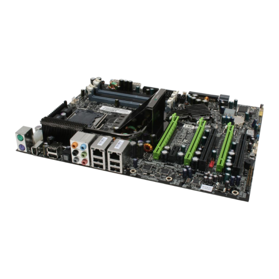
EVGA nForce 780i SLI Motherboard The EVGA nForce 780i SLI motherboard with the NVIDIA nForce 780i SLI SPP and MCP processors is a PCI Express, SLI-ready motherboard. Figure 1 shows the motherboard and Figures 2 shows the back panel connectors. - Page 17 26. Backpanel connectors (Figure 2) 7. Serial-ATA (SATA) connectors 17. Power button 27. Heat dissipater 8. FDD connector 18. Reset Button 28. 8-pin ATX_12V power connector 9. NVIDIA MCP (passive heat sink) 19. Azalia HD Audio Header 29 MCP/SPP fan connector EVGA...
-
Page 18: Figure 1. Evga Nforce 780I Sli Motherboard Layout
780i SLI Motherboard 10. Serial-ATA (SATA) connectors 20. FP Audio connector Figure 1. EVGA nForce 780i SLI Motherboard Layout 1. PS/2 Mouse Port 2. PS/2 Keyboard Port 3. 1394a (Firewire) Port 4. USB 2.0 ports (SIX) 5. SPDIF output 6. - Page 19 780i 3-Way SLI Motherboard EVGA...
-
Page 20: Hardware Installation
Hardware Installation This section will guide you through the installation of the motherboard. The topics covered in this section are: Preparing the motherboard Installing the CPU Installing the CPU fan Installing the memory Installing the motherboard Connecting cables and setting switches Safety Instructions To reduce the risk of fire, electric shock, and injury, always follows basic safety precautions. -
Page 21: Preparing The Motherboard
Align the notches in the processor with the notches on the socket. Lower the processor straight down into the socket Align notches with notches on the CPU with out tilting or sliding it into the socket EVGA... -
Page 22: Installing The Cpu Fan
Hardware Installation Note: Make sure the CPU is fully seated and level in the socket. Close the load plate over the CPU and press down while you close and engage the socket lever. Installing the CPU Fan There are many different fan types that can be used with this motherboard. Follow the instruction that came with you fan assembly. -
Page 23: Installing The Motherboard
Before installing the motherboard, install the I/O shield from the inside of the chassis. Press the I/O shield into place and make sure it fits securely. If the I/O shield does not fit into the chassis, you would need to obtain the proper size from the chassis supplier. EVGA... -
Page 24: Securing The Motherboard Into The Chassis
Hardware Installation Securing the Motherboard into the Chassis Most computer chassis have a base with mounting studs or spacers to allow the mother board to be secured to the chassis and help to prevent short circuits. If there are studs that do not align with a mounting hole on the motherboard, it is recommended that you remove that stud to prevent the possibility of a short circuit. -
Page 25: Power Connections
Six PCI-E power connectors configured in either of the following configurations (see Figure 3): Four 6-pin (3x2) and two 8-pin (4x2) PCI-E power connectors Six 6-pin (3x2) PCI-E power connectors 8-pin (4x2) PCT-E Connector 6-pin (3x2) PCI-E connector Figure 3. Power Supply Connectors EVGA... -
Page 26: 24-Pin Atx Power (Pwr1)
Hardware Installation Make sure you have enough power to cover all the expansion cards you will be installing. To determine what you power requirements are for your specific configuration or a certified power supply vendor, refer to www.slizone.com 24-pin ATX Power (PWR1) PWR1 is the main power supply connector located along the edge of the board... -
Page 27: 8-Pin Atx 12V Power (Pwr2)
Connect the gray connector to a slave device. If you install two hard disk drives, you must configure the second drive as a slave device by setting its jumper accordingly. Refer to the hard disk documentation for the jumper settings. EVGA... - Page 28 Hardware Installation Note: If an ATA-66/100 disk drive and a disk drive using any other IDE transfer protocol are attached to the same cable, the maximum transfer rate between the drives may be reduced to that of the slowest drive.
-
Page 29: Connecting Serial Ata Cables
RAID 1, RAID 5, RAID 0+1 and JBOD configurations. SATA 3 SATA 4 SATA 6 SATA 5 SATA 1 (bottom) Connect the locking cable end to the motherboard connector. SATA 2 (top) Connect the end without the lock to the drive. EVGA... -
Page 30: Connecting Internal Headers
Hardware Installation Connecting Internal Headers Front Panel Header The front panel header on this motherboard is one connector used to connect the following four cables (see Table 2 for pin definitions): Blank No Connect PWRLED Attach the front panel power LED PWRSW RESET cable to these two pins of the connector. -
Page 31: Ieee 1394A
Connect the two ends of the cables to the IEEE 1394 connectors on the motherboard. Table 3. IEEE 1394a Connector Pins Connector Signal TPA+ IEEE 1394a Connector TPA- TPB+ TPB- +12V +12V Empty EVGA... -
Page 32: Usb Headers
Hardware Installation USB Headers This motherboard contains six (6) USB 2.0 ports that are exposed on the rear panel of the chassis (Figure 2). The motherboard also contains two 10-pin internal header connectors onboard that can be used to connect an optional external bracket containing four (4) more USB 2.0 ports. -
Page 33: Audio
The audio connector supports HD audio standard and provides two kinds of audio output choices: the Front Audio, the Rear Audio. The front Audio supports re-tasking function. Table 5. Front Audio Connector Connector Signal Front Audio Connector PORT1_L AUD_GND PORT1_R PRECENCE_J PORT2_R SENSE1_RETURN SENSE_SEND Empty PORT2_L SENSE2_RETURN EVGA... -
Page 34: Fan Connections
Hardware Installation Fan Connections There are five fan connections on the motherboard. The fan speed can be detected and viewed in the section of the CMOS Setup. The PC Health Status fans are automatically turned off after the system enters S3, S4 and S5 mode. Note that the CPU fan cable can be either a 3-pin or a 4-pin connector. -
Page 35: Com1
System fan connector COM1 The motherboard kit provides an additional serial COM header for your machine. Connect one side of a switching cable to the header and then attach the serial COM device to the other side of the cable. EVGA... -
Page 36: Fdd Connector
(FDD). Expansion Slots The EVGA nForce 780i SLI motherboard contains six expansion slots, four PCI Express slots and two PCI slots. For a full list of PCI Express x16 graphics card supported by this motherboard, go to www.nvidia.com/estore... -
Page 37: Pci Express X1 Slot
Secure the card’s metal bracket to the chassis back panel with the screw used to hold the blank cover. To configure for SLI, follow the instructions that come with the SLI kit (the kit is purchased separately from the motherboard). EVGA... -
Page 38: Jumper Settings
Hardware Installation Jumper Settings The motherboard contains a 3-pin BIOS configuration jumper that enables all board configurations to be done in the BIOS Setup program. The silk screen on the motherboard shows a ∆ next to pin 1. Clear CMOS Jumper: CLR_CMOS The motherboard uses the CMOS RAM to store all the set parameters. - Page 39 780i 3-Way SLI Motherboard EVGA...
-
Page 40: Configuring The Bios
Configuring the BIOS This section discusses how to change the system settings through the BIOS Setup menus. Detailed descriptions of the BIOS parameters are also provided. This section includes the following information: Enter BIOS Setup Main Menu Standard CMOS Features Advanced BIOS Features Advanced Chipset Features Integrated Peripherals... -
Page 41: Enter Bios Setup
To go back to the previous menu, press Note: Note that on the BIOS screens all data in white is for information only, data in yellow is changeable, data in blue is non-changeable, and data in a red box is highlighted for selection. EVGA... -
Page 42: Figure 5. Bios Cmos Setup Utility Main Menu
Configuring the BIOS Phoenix – AwardBIOS CMOS Setup Utility Standard CMOS Features System Monitor Advanced BIOS Features Load Defaults Advanced Chipset Features Set Password Save & Exit Setup Integrated Peripherals Exit Without Saving Power Management Setup PnP/PCI Configurations Esc : Quit : Select Item F10 : Save &... - Page 43 SLI-Ready Memory is a status indicator displayed at the bottom of the BIOS screen. The three status indicators are: Enabled: SLI-Ready memory is detected and enabled. Disabled: SLI-Ready memory is detected but disabled. Not Detected: SLI-Ready memory is not detected. EVGA...
-
Page 44: Standard Cmos Features Menu
Configuring the BIOS Standard CMOS Features Menu The Standard CMOS Features menu is used to configure the standard CMOS information, such as the date, time, HDD model, and so on. Use the Page Up keys to scroll through the options or press to display the Page Down Enter... -
Page 45: Date And Time
SATA Channel 5 Master [None] IDE HDD Auto-Detect [Press Enter] SATA Channel 6 Master [None] IDE Channel 0 Slave [Manual} Access Mode [CHS] Press ENTER to display Capacity 0 MB SATA Channel sub- Cylinder Head Precomp Landing Zone Sector EVGA... - Page 46 Configuring the BIOS IDE Auto-Detect [Press Enter] Extended IDE Drive [None} Access Mode Auto Capacity 0 MB Cylinder Head Precomp Landing Zone Sector...
- Page 47 Access Modes: Key in a DEC number : For HDD less than 528 MB. For HDD greater than 528 MB and :Move ENTER:Accept ESC:Abort supporting LBA (Logical Block Addressing). Large For HDD greater than 528 MB but not supporting LBA. EVGA...
-
Page 48: Drive A
Configuring the BIOS Auto Recommended mode. Drive A option allows you to select the kind of FDD to install. Drive A Options are: Press ENTER to display sub- Drive A [1.44, 3.5 in.] Halt On [All , But Keyboard] None Drive A 360K, 5.25 in. -
Page 49: Memory
1048576K BIOS POST determines the amount of base (or conventional) memory installed in the system. Extended Memory BIOS determines how much extended memory is present during the POST. Total Memory This value represents the total memory of the system. EVGA... -
Page 50: Advanced Bios Features
Configuring the BIOS Advanced BIOS Features Access the Advanced BIOS Features menu from the CMOS Utility Setup screen. Use the keys to scroll through the options or Page Up Page Down press Enter to display the sub-menu. Use the arrow keys to position the selector in the option you choose. -
Page 51: Removable Device Priority
2. Network 1 : <description of network> CPU Internal Cache Use this option to enable or disable the CPU internal cache. Use the Page Up keys to scroll through the options or press to display the Page Down Enter EVGA... -
Page 52: Quick Power On Self Test
Configuring the BIOS options in a sub-menu. Use the arrow keys to position the selector in the option you choose. Quick Power On Self Test Enabling this option allows the system to skip certain test while booting, which reduces the time needed to boot the system. Use the Page Up Page Down keys to toggle between... -
Page 53: Boot Up Numlock Status
780i 3-Way SLI Motherboard Boot Up NumLock Status This option allows you to select the power-on state of . Select NumLock activate the keyboard when the system is started. Select to disable NumLock key. NumLock EVGA... -
Page 54: Security Option
Configuring the BIOS Security Option The Security Options allows you to require a password every time the system boots or only when you enter setup. Select to require a password to gain Setup access to the CMOS Setup screen. Select to require a password to System access the CMOS Setup screen and when the system boots. -
Page 55: Advanced Chipset Features
Voltage control Load timing/voltage set [Press Enter] Save timing/voltage set [Press Enter] System BIOS Cacheable [Disabled] HPET Function [Enable] NVIDIA GPY Ex [Enable] :Move Enter:Select +/-/PU/PD:Value F10:Save ESC:Exit F1:General Help F5: Previous Values F7:Defaults Figure 8. Advanced Chipset Features EVGA... -
Page 56: System Clocks
Configuring the BIOS System Clocks Select from the Advanced Chipset Features menu and press System Clocks to display the System Clocks menu. From this menu, you are able to Enter specify frequency settings, HT multipliers, and Spread Spectrum settings. Note that in Figure 9, all of the options are listed. -
Page 57: Frequency Settings
PCI Express Bus, Slot 3 (the black slot farthest from the CPU). SPP< >MCP Ref Clock, MHz — Use the Page Up Page Down keys to scroll through the frequency options for the reference clock between the SPP chip and the MCP chip. EVGA... -
Page 58: Ht Multiplier
Configuring the BIOS HT Multiplier nForce SPP > nForce MCP — — Use the keys to scroll through the HT multiplier Page Up Page Down options and set the link speed from the SPP chip to the MCP chip. Values are through [1 x] [5 x]. -
Page 59: Fsb & Memory Config
F10:Save ESC:Exit F1:General Help F5: Previous Values F7:Defaults Figure 10. FSB & Memory Config Menu SLI-Ready Memory Use the keys to scroll through the SLI-Ready Page Up Page Down Memory options. The options are: Disabled CPUOC 0% CPUOC 1% EVGA... - Page 60 Configuring the BIOS CPUOC 2% CPUOC 3% CPUOC 4% CPUOC 5% CPUOC MAX When you select one of the options, the CPUOC x% FSB - Memory is set to and cannot be changed until Clock Mode Unlinked SLI- is set to Ready Memory Disable FSB and Memory Clock Mode...
- Page 61 Auto(4) x tRC Auto(28) x tWR Auto(7) x tWTR Auto(10) x tREF Auto 6.1uS :Move Enter:Select +/-/PU/PD:Value F10:Save ESC:Exit F1:General Help[ F5: Previous Values F7:Defaults Optimal Use the keys to select Optimal Page Up Page Down Optimal. EVGA...
- Page 62 Configuring the BIOS prohibits you from manually setting any timing. All timing is set for optimal performance.
- Page 63 : RAS#-to-RAS# or auto refresh time of the same bank (options are 1 through 31). : The Write recovery time (options are 2 through 7). : This is the minimum write-to-read delay with the same chip tWTR selected (options are 1 through 10). EVGA...
-
Page 64: Cpu Configuration
Configuring the BIOS : This is the DRAM refresh rate (options are , and tREF Auto 7.8uS 3.9uS CPU Configuration Select from the Advanced Chipset Features menu and CPU Configuration press Enter to display the CPU Configuration menu. Phoenix – AwardBIOS CMOS Setup Utility CPU Configuration Limit CPUID MaxVal [Disabled]... - Page 65 When this function is disabled, it forces the XD feature flag to always return to zero (0). Virtualization Technology When this function is enabled, it allows a VMM to utilize the additional hardware capabilities provided by Intel Virtualization Technology. CPU Core 1 This function allows you to enable or disable CPU Core. EVGA...
-
Page 66: System Voltages
Configuring the BIOS System Voltages Select from the Advanced Chipset Features menu and press System Voltages Enter to display the System Voltages menu. Phoenix – AwardBIOS CMOS Setup Utility System Voltages Parameters Settings Current Value Item Help CPU Core [Auto] 1.28 CPU FSB [Auto]... - Page 67 [Auto] set the voltage. GTLVREF Lane 3 This function defines the voltage level for GTLVREF Lane 3. Use the Page keys to select a voltage or select to automatically Page Down [Auto] set the voltage. EVGA...
-
Page 68: Nvmem Memory Test
Configuring the BIOS NVMEM Memory Test This function defines whether you run the NVIDIA memory testing module during POST. The options are Fast, Medium, Slow, and Disable. Load Timing/Voltage Set This function loads the system voltages and timing settings that were defined in the System Voltages menu. -
Page 69: Save Timing/Voltage Set
This function allows you to enable or disable the High Precision Even Timer (HPET). When , HPET is used as the timing hardware for multimedia Enabled and other time-sensitive application. When HPET is , the APIC Disabled timer is used. EVGA... -
Page 70: Integrated Peripherals Menu
Configuring the BIOS Integrated Peripherals Menu Select from the CMOS Setup Utility menu and Integrated Peripherals press to display the Integrated Peripherals menu. Enter Phoenix – AwardBIOS CMOS Setup Utility Integrated Peripherals IDE Function Setup [Press Enter] Item Help RAID Config [Press Enter] USB Config [Press Enter]... -
Page 71: Ide Function Setup
This function allows you to enable specific SATA controllers, enable all controllers, or disable all controllers. The options available are [SATA-0] , and [SATA-0+1] [Enable All] [Disabled] IDE Prefetch Mode Use this function to enable or disable the IDE Prefetch mode EVGA... -
Page 72: Raid Config
Configuring the BIOS RAID Config Press to display the RAID Config menu. Enter RAID Enable [Enabled] SATA 0 Primary RAID [Disabled] SATA 0 Secondary RAID [Disabled] SATA 1 Primary RAID [Disabled] SATA 1 Secondary RAID [Disabled] SATA 2 Primary RAID [Disabled] SATA 2 Secondary RAID... -
Page 73: Mac Config
Select if your drive does not support block mode. [Disabled] Onboard FDC Controller This function on the Integrated Peripherals menu allows you to enable or disable the onboard Floppy Disk Controller function. EVGA... -
Page 74: Onboard Serial Port 1
Configuring the BIOS Onboard Serial Port 1 This function on the Integrated Peripherals menu allows you to select the onboard serial port 1 function. Options are [3F8/IRQ4] [2E8/IRQ3] , and [3E8/IRQ4] [Auto] [Disabled]. Power Management Setup Menu Select from the CMOS Setup Utility menu and Power Management Setup press to display the Power Management Setup menu. -
Page 75: Acpi Function
[ 0] Time (hh:mm:ss) Alarm [0 : 0 : 0] To enter a day or time, use the keys to scroll through Page Up Page Down numbers or enter the number using the keyboard number or the keys. – EVGA... -
Page 76: Power On Function
Configuring the BIOS POWER ON Function This function on the Power Management Setup menu allows you to define the power-on function. Options for this function are: BUTTON ONLY Keyboard 98 Password When is selected, the function is [Password] KB Power ON Password enabled so that you must enter a password. -
Page 77: Pnp/Pci Configuration Menu
Reset Configuration Data [Disabled] Main Level Resources Controlled By [Auto(ESCD)] IRQ Resources Press Enter ** PCI Express relative items ** Maximum Payload Size [4096] :Move Enter:Select +/-/PU/PD:Value F10:Save ESC:Exit F1:General Help F5: Previous Values F7:Defaults Figure 15. PnP/PCI Configuration Menu EVGA... -
Page 78: Init Display First
Configuring the BIOS Init Display First This function on the PnP/PCI Configuration menu allows you to define if the initial display is in the PCI slot or in the PCI Express slot. Options are [PCI Slot] [PCIEx]. Reset Configuration Data This function on the PnP/PCI Configuration menu allows you to enable or disable the resetting of Extended System Configuration Data (ESCD) when you exit Setup. -
Page 79: Irq Resources
TLP payload size (in bytes) for the PCI Express devices. Use the Page Up Page Down keys to scroll through sizes or enter the number using the keyboard numbers or use the keys to go up and down the list of – sizes. EVGA... -
Page 80: System Monitor Menu
Configuring the BIOS System Monitor Menu Select from the CMOS Setup Utility menu and press Enter System Monitor display the System Monitor menu. Phoenix – AwardBIOS CMOS Setup Utility System Monitor Dynamic Fan Control [Press Enter] Item Help 47ºC/ 117ºF CPU Core 1.28V Main Level... -
Page 81: Dynamic Fan Control
To set the fan speed to a constant rate, select and then enter the speed from 0% to 100%. [Manual] Set the desired speed for the Aux, nForce, and Chassis fans from 0% to 100%. The system defaults to 100%. EVGA... - Page 82 Configuring the BIOS...
-
Page 83: Installing Drivers And Software
Windows XP 32bit and 64bit and is Vista-capable. The kit comes with a CD that contains drivers and additional NVIDIA software. The CD that has been shipped with your EVGA motherboard contains the following software and drivers: NVIDIA nForce motherboard drivers... -
Page 84: Driver Installation
Configuring the BIOS Driver Installation Insert the EVGA nForce 780i SLI installation CD for the motherboard included in the kit. The CD will autorun, install the drivers and utilities listed on the install screen. If the CD does not run, go to My Computer and click on the CD to open. -
Page 85: Using The Nvidia Software
Using the NVIDIA Software Built upon the foundation of NVIDIA’s core motherboard and GPU technologies, NVIDIA System Monitor and Performance Server software utilities bring consolidated reporting and control to the desktop in seamless fashion. Traditionally, users have been forced to endure a sequence of trial and error attempts within the BIOS in order to customize the operation and performance of the system to their needs. -
Page 86: Nvidia Performance Group Of Nvidia Control Panel
Using NVIDIA Software NVIDIA Performance Group of NVIDIA Control Panel You can start the NVIDIA Performance Group several ways: Double-click the icon on the desktop NVIDIA Performance Group Right-click on the desktop and select NVIDIA Control Panel From the Windows Control Panel, double-click the NVIDIA Control Panel NVIDIA Performance Server menus are located under the Performance... -
Page 87: Device Settings
780i 3-Way SLI Motherboard Device Settings Device Settings has two tabs, Current Hardware Settings Hardware . Under the tab there are settings for the Profiles Current Hardware Settings CPU, Motherboard, Memory, and GPU. EVGA... -
Page 88: Current Hardware Settings
Using NVIDIA Software Current Hardware Settings This option deals with CPU parameters and information. Here, the user has the ability to dynamically change FSB speeds, CPU Voltages, and CPU fan speeds. At all times, real-time values for CPU frequency and appropriate CPU multiplier are reported. - Page 89 Profile menu item. If a setting does not allow a change, it probably requires a reboot and should be changed in the BIOS or from the page (if Dynamic BIOS Access available). EVGA...
- Page 90 Using NVIDIA Software Memory Memory is one of the most critical components in terms of determining overall system stability and overclocking success, a wealth of information and options for memory modules is available. Both timings and voltage are dynamically adjustable, with real-time values for memory frequency, FSB frequency, and more being viewable to help dictate which settings are most appropriate.
- Page 91 Memory timing that determines the delay between a write command and a Precharge command is set to the same bank of memory. Adjustable from 1 to W to R Termination Turnaround The Write-to-Read time is the number of clock cycles between the last write EVGA...
- Page 92 Using NVIDIA Software data pair and the subsequent READ command to the same physical block. Adjustable from 1 to 15. RAS to CAS access The RAS-to-CAS access (tRCD) is the amount of time in cycles for issuing an active command and the read/write commands. Adjustable from 1 to 15. RAS to RAS Delay The RAS-to-RAS delay (tRRD) is the is the amount of cycles it takes to activate the next bank of memory (this is the opposite of tRAS).
- Page 93 Command Per Clock The Command Per Clock (tCPC) sets the Command Rate for the memory controller. The value shown cannot be changed Async Latency This value is filled in by the system and can not be changed by the user. EVGA...
- Page 94 Using NVIDIA Software The graphics processing unit (GPU) located on your video card(s) can be adjusted using interface. You can override the shipped clock Device Setting frequencies of your GPU and GPU memory, and you can set the GPU fan speed.
-
Page 95: Dynamic Bios Access
The BIOS page chosen determines which items on the page are available for changing. To edit an item, select the corresponding list arrow and then select one of the Apply values from the list. When finished making your changes, click the EVGA... -
Page 96: View System Information
Using NVIDIA Software Note This feature is available only with BIOS support from the motherboard manufacturer. Available screen and features will vary between different makes and models of motherboards. View System Information View System Information menu is a high-level view where all the critical values of the system are consolidated and presented within a single view. -
Page 97: Profile Policies
When loading a game however, system settings adjust to extract the highest possible performance from every system component and ensure you have the ultimate gaming experience with your current hardware. EVGA... -
Page 98: Manage Your System Bios
Using NVIDIA Software Manage Your System BIOS Thanks to the power and flexibility of NVIDIA’s Performance Server software, users can even backup or update their system BIOS from within Windows. In addition to displaying a complete collection of information regarding the current BIOS version being used, the user also has the option of saving a backup version of the BIOS being used. -
Page 99: Nvidia System Monitor
The selected component comes to the foreground and all supported information is presented. Should the user prefer an overhead view of the components in the system, they can utilize the mouse-wheel to control the angle of the display. EVGA... - Page 100 Using NVIDIA Software In this example, we can see that the motherboard is selected. As a result, a wide array of related settings and status information is displayed in real-time. In addition to fan speeds and temperatures, we also find critical voltage values for core components.
- Page 101 From here, the component fields can be oriented and moved anywhere on the desktop. Furthermore, component fields can be removed from this view by clicking the small button in the top right of the icon’s box. EVGA...
- Page 102 Using NVIDIA Software By clicking on the Global Settings image in the bottom left of the screen, the user can nV Monitor customize the way looks and behaves. The first series of options the user is presented with deals with the application’s appearance. The user can control everything from temperature units to overall translucency of the application, and can manipulate a number of other settings to tailor the program to one’s liking.
- Page 103 All fields within the application will be logged and written to this file to aid in troubleshooting issues and tracking overall system behavior. EVGA...
- Page 104 Using NVIDIA Software The final series of options the user can change handles the specific hotkeys used to control various application actions. In this screen, the user simply enters their desired hotkey configuration and they are able to control every aspect of functionality for Monitor according to their own personal preferences.
-
Page 105: Appendix A. Post Codes For Tritium Platform
Appendix A. POST Codes for Tritium Platform This section provides the Award POST Codes (Table 6) and the NVMM POST Codes (Table 7) for Tritium platforms during system boot up. Table 6. Award POST Code Award POST Codes Name Description Reserved Jumps to E000 Execution of POST routines in E000... - Page 106 Post Codes Award POST Codes Name Description Test CMOS Test and Reset CMOS Reserved Load Chipset Load Chipset Defaults Reserved Init Clock Initialize onboard clock generator Reserved Init CPU CPU ID and initialize L1/L2 cache Reserved Reserved Setup Interrupt Initialize first 120 interrupt vectors with Vector Table SPURIOUS_INT_HDLR and initialize INT 00h-1Fh according to INT_TBL...
- Page 107 Reserved Test 8259-1 Mask Verify 8259 Channel 1 masked interrupts by alternately turning off and on the interrupt lines. Reserved Test 8259-2 Mask Verify 8259 Channel 2 masked interrupts by alternately turning off and on the interrupt lines. Reserved EVGA...
- Page 108 Post Codes Award POST Codes Name Description Reserved Test Stuck Turn off interrupts then verify no 8259's interrupt Interrupt mask register is on. Test 8259 Force an interrupt and verify the interrupt occurred. Reserved Reinit serial port Reinitialize Preboot agent serial port Reserved EISA Test If EISA non-volatile memory checksum is good,...
- Page 109 Initialize cache controller Reserved Setup Enter setup check and autoconfiguration check up Reserved Initialize Floppy Initialize floppy disk drive Reserved FDD install Install FDD and setup BIOS data area parameters Reserved Reserved Reserved Initialize Hard Initialize hard drive controller EVGA...
- Page 110 Post Codes Award POST Codes Name Description Drive Reserved Detect HDD IDE device detection Reserved Detect serial ports Initialize serial ports. Reserved Reserved Detect parallel Initialize parallel ports. ports Reserved HDD Write Protect HDD check for write protection Reserved Reserved POST error check Check POST error and display them and ask for user intervention...
- Page 111 If interrupt occurs in protected mode. Unclaimed NMI If unmasked NMI occurs, display Press F1 to disable NMI, F2 reboot. Program MCP To program chipset from defaults values Setup Pages E1- Page 1, E2 - Page 2, etc. Boot EVGA...
- Page 112 Post Codes Table 7. NVMM POST Codes NVMM POST Codes Code Name Description 0F0h Identify HW in the system 0F1h Register the slam tables 0F2h Early SLAM table 0F3h COM port initialization 000h Initialize the hardware devices 001h Override input parameters, etc. before QUERY 004h Query the hardware devices 008h...
- Page 113 North Bridge not supported 0FCh South Bridge not supported 0FBh No DIMMs present 0FAh Invalid DIMM types, SDR/DDR 0F9h Different voltage levels 0F8h Invalid REFRESH Rate 0F7h Invalide memory geometry 0F6h Slam Engine error 0F5h Memory Test Error 0F4h Link Training timeout EVGA...
- Page 114 Post Codes...
-
Page 115: Appendix B. Configuring An Sli Configuration
Appendix B. Configuring an SLI Configuration NVIDIA SLI (Scalable Link Interface) is a revolutionary technology that allows two NVIDIA SLI graphics cards to work together to deliver incredible 3D graphics performance. Your new motherboard can support up to three PCI Express graphics cards linked using SLI. -
Page 116: Forceware Driver
Figure 17. 3-way NVIDIA SLI connector (600-10732-0000-000) ForceWare Driver The 3-way SLI platform uses the NVIDIA ForceWare Windows Vista driver. To install the driver, run the setup.exe file to launch thee . The InstallShield runs three installs, one for each GPU. Reboot your PC when the InstallShield install is complete. -
Page 117: Figure 18. Windows Vista Device Manager
780i 3-Way SLI Motherboard Three GPUs are represented under Display adapters Figure 18. Windows Vista Device Manager EVGA... -
Page 118: Enabling 3-Way Sli
Enabling 3-Way SLI 3-way NVIDIA SLI is enabled from the . Right mouse NVIDIA Control Panel click on the Windows desktop and select NVIDIA Control Panel. Go to (Figure 19) and select Settings Set SLI configuration Enable SLI technology . After selecting this option, you will be prompted to verify the (recommended) settings have been successfully configured. -
Page 119: Figure 20. Sli Visual Indicators Operating In 3Dmark2006
3D Settings Show SLI Visual Indicators This option overlays a text label of SLI x3 and green SLI scaling bars in fullscreen 3D applications, as seen in Figure 20. Figure 20. SLI Visual Indicators Operating in 3DMark2006 EVGA... -
Page 120: Verifying 3-Way Sli Is Active
Verifying 3-way SLI is Active You can verify 3-way SLI is active and functional by launching a fullscreen 3D application and checking for the SLI Visual indicators. If these visual indicators are visible and there is no flickering or flashing, 3-way NVIDIA SLI is operational on your platform. -
Page 121: Index
Index 1394 Cable, 4 CPU Configuration, 48 2-Port SATA Power Cable, 4 FSB & Memory Config, 44 ACPI function, 59 Integrated Peripherals, 54 ACPI Suspend Type, 59 Main Menu, 28 Adjust Motherboard Timings screen, Memory Timing Setting, 46 PnP/PCI Configuration, 61 Advanced BIOS Features, 36 Power Management Setup, 58 Advanced Chipset Functions menu, 40... - Page 122 configure IDE and SATA channels, date and time, setting in BIOS, 32 BIOS, 32 DDR2 memory, 9 configuring the BIOS, 27 Device Settings, 71 connectors drivers, shipped in kit, 67 COM1, 22 dual channel DDR2, 9 CPU fan, 21 Dynamic BIOS Access page, 78 FDD, 23 Dynamic Fan Control menu, 65 front audio, 20...
- Page 123 IEEE 1934a Connector Pins, 18 set date and time, 32 installing set disk priority, 37 CPU, 8 set fan speeds in BIOS, 64 I/O shield, 10 set fan speeds with BIOS, 66 memory DIMMs, 9 set GPU parameters, 77 motherboard, 10 EVGA...
- Page 124 NumLock status, 38 Intel microprocessor, ix NVIDIA EX support, 53 internal headers, 17 NVIDIA memory testing module, 52 PWRHD_LED, 17 EVGA nForce 780i Motherboard, 3 PWRLED, 17 EVGA nForce 780i Motherboard Layout, 5 PWRSW, 17 NVIDIA Performance Group, 70 IRQ Resources, 63...
- Page 125 Refresh Rate, 75 Total Memory, 35 removable device startup priority, 37 tRAS, 47, 74 RESET, 17 tRC, 47 Reset switch cable, 17 tRDC, 47 Row Address Strobe, 74 tRDRD, 75 Row Cycle Time, 75 tREF, 47 safety instructions, 7 tRP, 47 EVGA...
- Page 126 tRRD, 47 USB Config menu, 56 tWR, 47 USB Keyboard/Mouse Support, 56 tWRD, 76 View System Information menu, tWRWR, 76 Virtualization Technology, 49 tWTR, 47 W to R Termination Turnaround, 75 unpacking the kit, 3 Write Recovery Time, 75 USB 2.0 4-Port Cable, 4 Write-to-Write timing, 76 USB 2.0 ports, 19...
Need help?
Do you have a question about the 780i - nForce SLI 775 A1 Motherboard and is the answer not in the manual?
Questions and answers