Table of Contents
Advertisement
Advertisement
Table of Contents

Related Manuals for EVGA 132-CK-NF79-A1


Summary of Contents for EVGA 132-CK-NF79-A1
- Page 2 User Guide EVGA nForce 790i Ultra SLI Motherboard EVGA Corporation January, 2008 | DU-03597-001_v01...
- Page 3 790i Ultra SLI Motherboard EVGA Corporation January 11, 2008 | DU-03751-001_v01...
-
Page 4: Table Of Contents
EVGA nForce 790i Motherboard ................1 Motherboard Specifications..................1 Unpacking and Parts Descriptions ................4 Unpacking ........................ 4 Equipment ........................ 4 EVGA nForce 790i Ultra SLI Motherboard............... 5 Hardware Installation ....................8 Safety Instructions ....................8 Preparing the Motherboard..................9 Installing the CPU ....................9 Installing the CPU Fan .................. - Page 5 Date and Time....................34 IDE Channel and SATA Channel................ 34 Drive A........................ 37 Halt On ....................... 37 Memory ......................38 Advanced BIOS Features..................39 Removable Device Priority................. 40 Hard Disk Boot Priority ..................40 EVGA Corporation January 11, 2008 | DU-03751-001_v01...
- Page 6 Load Timing/Voltage Set..................57 Save Timing/Voltage Set..................58 System BIOS Cacheable ................... 58 Integrated Peripherals Menu.................. 59 IDE Function Setup .................... 60 RAID Config ....................... 61 USB Config ......................61 MAC Config......................62 IEEE1394 controller.................... 62 EVGA Corporation January 11, 2008 | DU-03751-001_v01...
- Page 7 Windows XP Drivers Install ..................74 Using the NVIDIA Software..................75 NVIDIA Performance Group of NVIDIA Control Panel ........... 76 Device Settings ....................77 Current Hardware Settings ................78 Dynamic BIOS Access ..................85 View System Information ................... 86 EVGA Corporation January 11, 2008 | DU-03751-001_v01...
- Page 8 Appendix A. POST Codes for Tritium Platform ............95 Appendix B. Configuring an SLI Configuration ............. 105 SLI Connector ...................... 106 ForceWare Driver ....................106 Enabling 3-Way SLI..................108 Verifying 3-way SLI is Active................110 Index ................Error! Bookmark not defined. EVGA Corporation January 11, 2008 | DU-03751-001_v01...
- Page 9 790i Ultra SLI Motherboard List of Figures Figure 1. EVGA nForce 790i Ultra SLI Motherboard Layout ......... 6 Figure 2. Chassis Backpanel Connectors ............. 7 Figure 3. Power Supply Connectors ..............15 Figure 4. PWR1 Motherboard Connector ............15 Figure 5.
-
Page 10: Before You Begin
Parts NOT in the Kit This kit contains all the hardware necessary to install and connect your new EVGA a nForce® 790i Ultra SLI motherboard. However, it does not contain the following items that must be purchased separately to make the motherboard functional. -
Page 11: Intentions Of The Kit
When replacing a motherboard in a PC cabinet, you will need to reinstall an operating system even though the current drives have an operating system. EVGA Corporation January 11, 2008 | DU-03751-001_v01... -
Page 12: Evga Nforce 790I Motherboard
EVGA nForce 790i Ultra SLI Motherboard Thank you for buying the EVGA NFORCE 790i Ultra SLI Motherboard. This motherboard offers the tools and performance PC users’ demand. When combined with two or three SLI-Ready NVIDIA GeForce graphics cards, you get innovative NVIDIA SLI Technology for enhanced system performance. - Page 13 Supports S0 (normal), S1 (power on suspend), S3 (suspend to RAM), S4 (Suspend to disk - depends on OS), and S5 (soft - off) Expansion Slots Two PCI slots One PCI Express x1 slot Three PCI Express x16 Graphics slots EVGA Corporation January 11, 2008 | DU-03751-001_v01...
- Page 14 790i SLI Motherboard EVGA Corporation January 11, 2008 | DU-03751-001_v01...
-
Page 15: Unpacking And Parts Descriptions
All parts shipped in this kit are RoHS-compliant (lead-free) parts. Equipment The following equipment is included in the EVGA nForce 790i Ultra SLI motherboard box. EVGA nForce 790i Ultra SLI Motherboard This PCI Express motherboard contains the NVIDIA nForce 790i Ultra SLI SPP and MCP and is SLI-ready. -
Page 16: Evga Nforce 790I Ultra Sli Motherboard
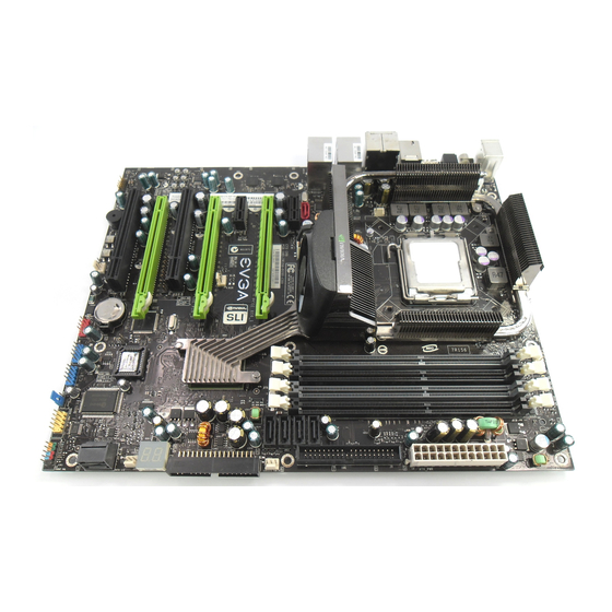
EVGA nForce 790i Ultra SLI Motherboard The EVGA nForce 790i Ultra SLI motherboard with the NVIDIA nForce 790i Ultra SLI SPP and MCP processors is a PCI Express, SLI-ready motherboard. Figure 1 shows the motherboard and Figures 2 shows the back panel connectors. -
Page 17: Figure 1. Evga Nforce 790I Ultra Sli Motherboard Layout
28. MCP/SPP fan connector (not used) 9. NVIDIA MCP (passive heat sink) 19. Reset Button 29. Motherboard battery 10. Diagnostic code display 20. Front panel Audio connector Figure 1. EVGA nForce 790i Ultra SLI Motherboard Layout EVGA Corporation January 11, 2008 | DU-03751-001_v01... -
Page 18: Figure 2. Chassis Backpanel Connectors
9. Lan Port with LEDs to indicate status. Yellow/Light Up/Blink = 10 Mbps/Link/Activity • Yellow and Green/Light Up/Blink = 100 Mbps/link/Activity • Green/Light Up/Blink = 1000 Mbps/Link/Activity • Figure 2. Chassis Backpanel Connectors EVGA Corporation January 11, 2008 | DU-03751-001_v01... -
Page 19: Hardware Installation
To reduce the risk of fire, electric shock, and injury, always follow basic safety precautions. Remember to remove power from your computer by disconnecting the AC main source before removing or installing any equipment from/to the computer chassis. EVGA Corporation January 11, 2008 | DU-03751-001_v01... -
Page 20: Preparing The Motherboard
Align the notches in the processor with the notches on the socket. Lower the processor straight down into the socket Align notches with with out tilting or sliding it into the socket notches on the CPU EVGA Corporation January 11, 2008 | DU-03751-001_v01... -
Page 21: Installing The Cpu Fan
Two DIMMs: Install into either slots 0 and 1 or 2 and 3. The idea is to not have the DIMMs in adjacent slots. Four DIMMS: Install into slots 0, 1, 2, and 3. CPU side DIMM Slot 0 DIMM Slot 2 DIMM Slot 1 DIMM Slot 3 Card-edge EVGA Corporation January 11, 2008 | DU-03751-001_v01... - Page 22 Hardware Installation EVGA Corporation January 11, 2008 | DU-03751-001_v01...
-
Page 23: Installing The Motherboard
Press the I/O shield into place and make sure it fits securely. If the I/O shield does not fit into the chassis, you would need to obtain the proper size from the chassis supplier. EVGA Corporation January 11, 2008 | DU-03751-001_v01... -
Page 24: Securing The Motherboard Into The Chassis
This section takes you through all the connections and switch settings necessary on the motherboard. This will include: Power Connections 24-pin ATX power ( PWR1 8-pin ATX 12V power ( PWR2 Internal Headers Front panel IEEE 1394a USB Headers Audio EVGA Corporation January 11, 2008 | DU-03751-001_v01... -
Page 25: Power Connections
Six PCI-E power connectors configured in either of the following configurations (see Figure 3): Four 6-pin (3x2) and two 8-pin (4x2) PCI-E power connectors Six 6-pin (3x2) PCI-E power connectors 8-pin (4x2) PCT-E Connector 6-pin (3x2) PCI-E connector EVGA Corporation January 11, 2008 | DU-03751-001_v01... -
Page 26: 24-Pin Atx Power (Pwr1)
PWR1 connector Plug power cable from system power supply to PWR1 Card edge Figure 4. PWR1 Motherboard Connector Table 1. PWR1 Pin Assignments Connector Signal Signal +3.3V +3.3V +3.3V -12V PS_ON PWROK RSVD EVGA Corporation January 11, 2008 | DU-03751-001_v01... -
Page 27: 8-Pin Atx 12V Power (Pwr2)
Connect the gray connector to a slave device. If you install two hard disk drives, you must configure the second drive as a slave device by setting its jumper accordingly. Refer to the hard disk documentation for the jumper settings. EVGA Corporation January 11, 2008 | DU-03751-001_v01... - Page 28 If an ATA-66/100 disk drive and a disk drive using any other IDE transfer protocol are attached to the same cable, the maximum transfer rate between the drives may be reduced to that of the slowest drive. EVGA Corporation January 11, 2008 | DU-03751-001_v01...
-
Page 29: Connecting Serial Ata Cables
RAID 0, RAID 1, RAID 5, RAID 0+1 and JBOD configurations. SATA 3 SATA 4 SATA 6 SATA 5 SATA 1 (bottom) Connect the locking cable end to the motherboard connector. SATA 2 (top) Connect the end without the lock to the drive. EVGA Corporation January 11, 2008 | DU-03751-001_v01... -
Page 30: Connecting Internal Headers
HDD indicator LED indicates the activity status of the hard disks. RESET Attach the Reset switch cable from the front panel of the case to these two pins. The system restarts when the switch is pressed. RESET EVGA Corporation January 11, 2008 | DU-03751-001_v01... -
Page 31: Ieee 1394A
Connect the two ends of the cables to the IEEE 2394 connectors on the motherboard. Table 3. IEEE 1394a Connector Pins Connector Signal TPA+ IEEE 1394a Connector TPA- TPB+ TPB- Card Edge +12V +12V Empty EVGA Corporation January 11, 2008 | DU-03751-001_v01... -
Page 32: Usb Headers
Connect the two ends of the cables to the USB 2.0 headers on the motherboard. Card Edge Table 4. USB 2.0 Header Pins Connector Signal USB 2.0 Header Connector 5V_DUAL Empty Signal 5V_DUAL No Connect EVGA Corporation January 11, 2008 | DU-03751-001_v01... -
Page 33: Audio
Front Audio, the Rear Audio. The front Audio supports re-tasking function. Table 5. Front Audio Connector Connector Signal Front Audio Connector PORT1_L AUD_GND PORT1_R PRECENCE_J PORT2_R SENSE1_RETURN Card Edge SENSE_SEND Empty PORT2_L SENSE2_RETURN EVGA Corporation January 11, 2008 | DU-03751-001_v01... -
Page 34: Fan Connections
Note that the CPU fan cable can be either a 3-pin or a 4-pin connector. Connect a 3-pin connector to pins 1, 2, and 3 on the motherboard connector. Connector CPU Fan SENSE CONTROL EVGA Corporation January 11, 2008 | DU-03751-001_v01... -
Page 35: Com1
The motherboard kit provides an additional serial COM header for your machine. Connect one side of a switching cable to the header and then attach the serial COM device to the other side of the cable. EVGA Corporation January 11, 2008 | DU-03751-001_v01... -
Page 36: Fdd Connector
2.88M floppy disk drive (FDD). Expansion Slots The EVGA nForce 790i Ultra SLI motherboard contains seven expansion slots, five PCI Express slots and two PCI slots. For a full list of PCI Express x16 graphics card supported by this motherboard, go to www.nvidia.com/estore... -
Page 37: Pci Slots
If the card is not seated properly, it could cause a short across the pins. Secure the card’s metal bracket to the chassis back panel with the screw used to hold the blank cover. EVGA Corporation January 11, 2008 | DU-03751-001_v01... -
Page 38: Jumper Settings
Connect pins 1 and 2 together using the jumper cap. Return the jumper setting to normal (pins 2 and 3 together with the jumper cap). Card Turn the AC power supply back on. Edge EVGA Corporation January 11, 2008 | DU-03751-001_v01... -
Page 39: Configuring The Bios
Setup menus. Detailed descriptions of the BIOS parameters are also provided. This section includes the following information: Enter BIOS Setup Main Menu Standard CMOS Features Advanced BIOS Features Advanced Chipset Features Integrated Peripherals Power Management Setup PnP/PCI Configurations System Monitor EVGA Corporation January 11, 2008 | DU-03751-001_v01... -
Page 40: Enter Bios Setup
Note that on the BIOS screens all data in white is for information only, data in yellow is changeable, data in blue is non-changeable, and data in a red box is highlighted for selection. EVGA Corporation January 11, 2008 | DU-03751-001_v01... -
Page 41: Figure 5. Bios Cmos Setup Utility Main Menu
Integrated Peripherals Use this menu to set up onboard peripherals such as IDE, RAID, USB, LAN, and MAC control. Power Management Setup Use this menu to configure power management, power on, and sleep features. EVGA Corporation January 11, 2008 | DU-03751-001_v01... - Page 42 SLI-Ready Memory is a status indicator displayed at the bottom of the BIOS screen. The three status indicators are: Enabled: SLI-Ready memory is detected and enabled. Disabled: SLI-Ready memory is detected but disabled. Not Detected: SLI-Ready memory is not detected. EVGA Corporation January 11, 2008 | DU-03751-001_v01...
-
Page 43: Standard Cmos Features Menu
[1.44, 3.5 in.] Halt On [All , But Keyboard] Base Memory 640K Extended Memory 1047552K Total Memory 1048576K :Move Enter:Select +/-/PU/PD:Value F10:Save ESC:Exit F1:General Help F5: Previous Values F7:Defaults Figure 6. Standard CMOS Features Menu EVGA Corporation January 11, 2008 | DU-03751-001_v01... - Page 44 Configuring the BIOS Note: Note that all data in white is for information only, data in yellow is changeable, data in blue is non-changeable, and data in a red box is highlighted for selection. EVGA Corporation January 11, 2008 | DU-03751-001_v01...
-
Page 45: Date And Time
SATA Channel 5 Master [None] SATA Channel 6 Master [None] IDE Channel 0 Slave [Manual} Access Mode [CHS] Press ENTER to display Capacity 0 MB SATA Channel sub- Cylinder Head Precomp Landing Zone Sector EVGA Corporation January 11, 2008 | DU-03751-001_v01... - Page 46 Configuring the BIOS IDE Auto-Detect [Press Enter] Extended IDE Drive [None} Access Mode Auto Capacity 0 MB Cylinder Head Precomp Landing Zone Sector EVGA Corporation January 11, 2008 | DU-03751-001_v01...
- Page 47 Key in a DEC number : For HDD less than 528 MB. :Move ENTER:Accept ESC:Abort For HDD greater than 528 MB and supporting LBA (Logical Block Addressing). Large For HDD greater than 528 MB but not supporting LBA. EVGA Corporation January 11, 2008 | DU-03751-001_v01...
-
Page 48: Drive A
Use Enter Halt On arrow keys to position the selector in the option you choose. Press to accept the changes and return to the Standard CMOS Features Enter menu. EVGA Corporation January 11, 2008 | DU-03751-001_v01... -
Page 49: Memory
(or conventional) memory installed in the system. Extended Memory BIOS determines how much extended memory is present during the POST. Total Memory This value represents the total memory of the system. EVGA Corporation January 11, 2008 | DU-03751-001_v01... -
Page 50: Advanced Bios Features
Security Option [Setup] APIC Mode [Enabled] MPS Version Control For OS [1.4] Full Screen LOGO Show [Disabled] :Move Enter:Select +/-/PU/PD:Value F10:Save ESC:Exit F1:General Help F5: Previous Values F7:Defaults Figure 7. Advanced BIOS Features Menu EVGA Corporation January 11, 2008 | DU-03751-001_v01... -
Page 51: Removable Device Priority
– the device priority up or down in the list. To go back to the previous menu, press Esc. 1. Network 0 : <description of network> 2. Network 1 : <description of network> EVGA Corporation January 11, 2008 | DU-03751-001_v01... -
Page 52: Cpu Internal Cache
First Boot Device Removable ..[ ] Hard Disk ..[ ] CDROM ..[ ] Network ..[ ] Disabled ..[ ] :Move ENTER:Accept ESC:Abort EVGA Corporation January 11, 2008 | DU-03751-001_v01... -
Page 53: Boot Other Device
Boot Up NumLock Status This option allows you to select the power-on state of . Select NumLock to activate the keyboard when the system is started. Select NumLock disable the key. NumLock EVGA Corporation January 11, 2008 | DU-03751-001_v01... -
Page 54: Security Option
Full Screen LOGO Show This option allows you to enable or disable the display of the full-screen logo when the system boots. Use the keys to Page Up Page Down toggle between Enable Disable EVGA Corporation January 11, 2008 | DU-03751-001_v01... -
Page 55: Advanced Chipset Features
Load timing/voltage set [Press Enter] Save timing/voltage set [Press Enter] System BIOS Cacheable [Disabled] HPET Function [Enable] :Move Enter:Select +/-/PU/PD:Value F10:Save ESC:Exit F1:General Help F5: Previous Values F7:Defaults Figure 8. Advanced Chipset Features EVGA Corporation January 11, 2008 | DU-03751-001_v01... -
Page 56: System Clocks
System Clocks Menu Note: Note that all data in white is for information only, data in yellow is changeable, data in blue is non-changeable, and data in a red box is highlighted for selection. EVGA Corporation January 11, 2008 | DU-03751-001_v01... -
Page 57: Frequency Settings
PCI Express Bus, Slot 3 (the black slot farthest from the CPU). SPP< — >MCP Ref Clock, MHz Use the keys to scroll through the frequency Page Up Page Down options for the reference clock between the SPP chip and the MCP chip. EVGA Corporation January 11, 2008 | DU-03751-001_v01... -
Page 58: Ht Multiplier
Spectrum options for the SPP PCIe. Option values are [Disabled] , and This option reverts to Spread] [Center Spread]. Disabled cannot be changed when the value for PCIe x16_1 exceeds 100MHz. PCIe Spread Spectrum(MCP) Disabled SATA Spread Spectrum Disabled EVGA Corporation January 11, 2008 | DU-03751-001_v01... -
Page 59: Fsb & Memory Config
Figure 10. FSB & Memory Config Menu SLI-Ready Memory Use the keys to scroll through the SLI-Ready Page Up Page Down Memory options. The options are: Disabled CPUOC 0% CPUOC 1% CPUOC 2% EVGA Corporation January 11, 2008 | DU-03751-001_v01... - Page 60 When Unlink is selected, FSB (QDR), MHz MEM (DDR), MHz are changed to editable and the FSB and memory speeds can be entered manually. As the FSB speed is changed, CPU Freq, MHz changes proportionally. EVGA Corporation January 11, 2008 | DU-03751-001_v01...
-
Page 61: Memory Timing Setting
Auto(2T) ** Advanced Memory Settings ** x tRRD Auto(4) x tRC Auto(28) x tWR Auto(7) x tWTR Auto(10) x tREF Auto 6.1uS :Move Enter:Select +/-/PU/PD:Value F10:Save ESC:Exit F1:General Help[ F5: Previous Values F7:Defaults EVGA Corporation January 11, 2008 | DU-03751-001_v01... - Page 62 Configuring the BIOS Optimal Use the keys to select Optimal Page Up Page Down Optimal. prohibits you from manually setting any timing. All timing is set for optimal performance. EVGA Corporation January 11, 2008 | DU-03751-001_v01...
- Page 63 (options are 1 through 31). : The Write recovery time (options are 2 through 7). : This is the minimum write-to-read delay with the same tWTR chip selected (options are 1 through 10). EVGA Corporation January 11, 2008 | DU-03751-001_v01...
-
Page 64: Cpu Configuration
Use this function to enable the set limit of the CPUID MaxVal to 3. Set to Disable for Win XP. CPU Thermal Control Use this function to enable or disable TM1 and TM2 support. Options are: EVGA Corporation January 11, 2008 | DU-03751-001_v01... - Page 65 When this function is enabled, it allows a VMM to utilize the additional hardware capabilities provided by Intel Virtualization Technology. CPU Core 1 This function allows you to enable or disable CPU Core. EVGA Corporation January 11, 2008 | DU-03751-001_v01...
-
Page 66: System Voltages
CPU FSB. [Auto] Memory This function defines the voltage level for the DRAM. Use the Page Up keys to select a voltage or select to automatically Page Down [Auto] set the voltage. EVGA Corporation January 11, 2008 | DU-03751-001_v01... - Page 67 GTLVREF Lane 3 This function defines the voltage level for GTLVREF Lane 3. Use the keys to select a voltage or select Page Up Page Down [Auto] automatically set the voltage. EVGA Corporation January 11, 2008 | DU-03751-001_v01...
-
Page 68: Nvmem Memory Test
Enter Auto Load timing/voltage set Press Enter to Exit ..[ ] Select Profile 1 ..[ ] Select Profile 2 ..[ ] Select Profile 3 ..[ ] :Move ENTER:Accept ESC:Abort EVGA Corporation January 11, 2008 | DU-03751-001_v01... -
Page 69: Save Timing/Voltage Set
This function allows you to enable or disable the High Precision Even Timer (HPET). When , HPET is used as the timing hardware for Enabled multimedia and other time-sensitive application. When HPET is , the APIC timer is used. Disabled EVGA Corporation January 11, 2008 | DU-03751-001_v01... -
Page 70: Integrated Peripherals Menu
HD Audio [Auto] IDE HDD Block Mode [Enabled] Onboard FDC Controller [Enabled] Onboard Serial Port 1 [3FB/IRQ4] :Move Enter:Select +/-/PU/PD:Value F10:Save ESC:Exit F1:General Help F5: Previous Values F7:Defaults Figure 13. Integrated Peripherals Menu EVGA Corporation January 11, 2008 | DU-03751-001_v01... -
Page 71: Ide Function Setup
This function allows you to enable specific SATA controllers, enable all controllers, or disable all controllers. The options available are [SATA- , and [SATA-0+1] [Enable All] [Disabled] IDE Prefetch Mode Use this function to enable or disable the IDE Prefetch mode EVGA Corporation January 11, 2008 | DU-03751-001_v01... -
Page 72: Raid Config
, the keyboard [Disabled] and mouse support functions are set to Enabled OnChip USB [Disabled] cannot be changed. Versions USB Keyboard Support Enabled USB Mouse Support Enabled that can be selected are [V1.1+V2.0] [V1.1] EVGA Corporation January 11, 2008 | DU-03751-001_v01... -
Page 73: Mac Config
Select [Enabled] automatically detect the optimal number of block read/writes per sector the drive can support. Select if your drive does not support [Disabled] block mode. EVGA Corporation January 11, 2008 | DU-03751-001_v01... -
Page 74: Onboard Fdc Controller
Power Management Setup Menu Select from the CMOS Setup Utility menu and Power Management Setup press to display the Power Management Setup menu. Enter Phoenix – AwardBIOS CMOS Setup Utility Power Management Setup EVGA Corporation January 11, 2008 | DU-03751-001_v01... -
Page 75: Acpi Function
This function on the Power Management Setup menu allows you to enable or disable the ACPI function. ACPI Suspend Type This function on the Power Management Setup menu allows you to select an ACPI Suspend Type. Types to select from are [S1&S3] [S1(POS)] [S3(STR)] EVGA Corporation January 11, 2008 | DU-03751-001_v01... -
Page 76: Soft-Off By Pbnt
This function on the Power Management Setup menu allows you to define the power-on function. Options for this function are: BUTTON ONLY Keyboard 98 Password When is selected, the function [Password] KB Power ON Password is enabled so that you must enter a password. EVGA Corporation January 11, 2008 | DU-03751-001_v01... - Page 77 To select a hot key use though Ctrl+F1 Ctrl+F12 POWER ON Function [Hot key] KB Power ON Password Enter Hot Key Power On [Ctrl-F1] Mouse Left Mouse Right Any Key EVGA Corporation January 11, 2008 | DU-03751-001_v01...
-
Page 78: Pnp/Pci Configuration Menu
Resources Controlled By [Auto(ESCD)] IRQ Resources Press Enter ** PCI Express relative items ** Maximum Payload Size [4096] :Move Enter:Select +/-/PU/PD:Value F10:Save ESC:Exit F1:General Help F5: Previous Values F7:Defaults Figure 15. PnP/PCI Configuration Menu EVGA Corporation January 11, 2008 | DU-03751-001_v01... -
Page 79: Init Display First
If you select so you can [Manual] assign the resources, is enabled for input. IRQ Resources Resources Controlled By [Auto(ESCD)] x IRQ Resources Press Enter Resources Controlled By [Manual)] IRQ Resources [Press Enter] EVGA Corporation January 11, 2008 | DU-03751-001_v01... -
Page 80: Irq Resources
TLP payload size (in bytes) for the PCI Express devices. Use the keys to scroll through sizes or enter the number Page Up Page Down using the keyboard numbers or use the keys to go up and down – the list of sizes. EVGA Corporation January 11, 2008 | DU-03751-001_v01... -
Page 81: System Monitor Menu
F5: Previous Values F7:Defaults Figure 16. System Monitor Menu All of the values shown in are dynamic and change as the speed and Blue voltages of the various components change with system usage. EVGA Corporation January 11, 2008 | DU-03751-001_v01... -
Page 82: Dynamic Fan Control
[Manual] from 0% to 100%. Set the desired speed for the Aux, nForce, and Chassis fans from 0% to 100%. The system defaults to 100%. EVGA Corporation January 11, 2008 | DU-03751-001_v01... - Page 83 790i Ultra SLI Motherboard This page is blank. EVGA Corporation January 11, 2008 | DU-03751-001_v01...
-
Page 84: Installing Drivers And Software
Windows XP 32bit and 64bit and is Vista-capable. The kit comes with a CD that contains utility drivers and additional NVIDIA software. The CD that has been shipped with your EVGA motherboard contains the following software and drivers: NVIDIA nForce motherboard drivers... -
Page 85: Windows Xp Drivers Install
790i Ultra SLI Motherboard Drivers Installation Insert the NVIDIA EVGA nForce 780i SLI installation CD for the graphics drivers motherboard included in the kit. The CD will auto run, install the drivers and utilities listed on the install screen. -
Page 86: Using The Nvidia Software
From a single convenient interface, the user can adjust settings to minimize noise, optimize performance, and maximize system stability. In addition, a wealth of system information is readily available in a lush 3D presentation which is customizable to suit the user. EVGA Corporation January 11, 2008 | DU-03751-001_v01... -
Page 87: Nvidia Performance Group Of Nvidia Control Panel
Performance Group applies the same depth of control to the rest of the components within a system. Without ever leaving Windows or entering the BIOS, users can optimize and adjust nearly every system component. EVGA Corporation January 11, 2008 | DU-03751-001_v01... -
Page 88: Device Settings
Using NVIDIA Software Device Settings Device Settings has two tabs, Current Hardware Settings Hardware . Under the tab there are settings for Profiles Current Hardware Settings the CPU, Motherboard, Memory, and GPU. EVGA Corporation January 11, 2008 | DU-03751-001_v01... -
Page 89: Current Hardware Settings
Increasing the voltage or the clock speed of a component may void its warranty due to exceeding recommended specifications. NVIDIA and the board manufacturer are not responsible for damage that may occur when component tolerances are exceeded. EVGA Corporation January 11, 2008 | DU-03751-001_v01... - Page 90 Profile menu item. If a setting does not allow a change, it probably requires a reboot and should be changed in the BIOS or from the page (if Dynamic BIOS Access available). EVGA Corporation January 11, 2008 | DU-03751-001_v01...
- Page 91 Both timings and voltage are dynamically adjustable, with real-time values for memory frequency, FSB frequency, and more being viewable to help dictate which settings are most appropriate. EVGA Corporation January 11, 2008 | DU-03751-001_v01...
- Page 92 Precharge command is set to the same bank of memory. Adjustable from 1 to 15. W to R Termination Turnaround The Write-to-Read time is the number of clock cycles between the last EVGA Corporation January 11, 2008 | DU-03751-001_v01...
- Page 93 Adjustable from 1 to 63 cycles W to R Command Delay The Write-to-Read (tWRD) command delay is the amount of cycles required between a valid write command and the next read command. A EVGA Corporation January 11, 2008 | DU-03751-001_v01...
- Page 94 The Command Per Clock (tCPC) sets the Command Rate for the memory controller. The value shown cannot be changed Async Latency This value is filled in by the system and can not be changed by the user. EVGA Corporation January 11, 2008 | DU-03751-001_v01...
- Page 95 GPU and GPU memory, and you can set the GPU fan speed. Increasing the clock speeds will increase your GPU performance but may necessitate improved cooling to maintain the same level of reliability. EVGA Corporation January 11, 2008 | DU-03751-001_v01...
-
Page 96: Dynamic Bios Access
The BIOS page chosen determines which items on the page are available for changing. To edit an item, select the corresponding list arrow and then select one of the values from the list. When finished making your changes, click the Apply EVGA Corporation January 11, 2008 | DU-03751-001_v01... -
Page 97: View System Information
Within the View System section, the Information user can also double-click values for both memory modules and processors to EVGA Corporation January 11, 2008 | DU-03751-001_v01... -
Page 98: Profile Policies
When loading a game however, system settings adjust to extract the highest possible performance from every system component and ensure you have the ultimate gaming experience with your current hardware. EVGA Corporation January 11, 2008 | DU-03751-001_v01... -
Page 99: Manage Your System Bios
BIOS being used. This is especially useful when updating the current BIOS because you have a known good BIOS to revert to should the other version have issues with system stability or performance. EVGA Corporation January 11, 2008 | DU-03751-001_v01... -
Page 100: Nvidia System Monitor
The selected component comes to the foreground and all supported information is presented. Should the user prefer an overhead view of the components in the system, they can utilize the mouse-wheel to control the angle of the display. EVGA Corporation January 11, 2008 | DU-03751-001_v01... - Page 101 By moving the slider on the bottom of the screen, the user also can control the translucency of the screen allowing them to view the desktop if desired. EVGA Corporation January 11, 2008 | DU-03751-001_v01...
- Page 102 From here, the component fields can be oriented and moved anywhere on the desktop. Furthermore, component fields can be EVGA Corporation January 11, 2008 | DU-03751-001_v01...
- Page 103 The user can control everything from temperature units to overall translucency of the application, and can manipulate a number of other settings to tailor the program to one’s liking. EVGA Corporation January 11, 2008 | DU-03751-001_v01...
- Page 104 All fields within the application will be logged and written to this file to aid in troubleshooting issues and tracking overall system behavior. EVGA Corporation January 11, 2008 | DU-03751-001_v01...
- Page 105 In this screen, the user simply enters their desired hotkey configuration and they are able to control every aspect of functionality for according to their own personal preferences. nV Monitor EVGA Corporation January 11, 2008 | DU-03751-001_v01...
-
Page 106: Appendix A. Post Codes For Tritium Platform
Test the Keyboard Reserved Mouse Init Initialized the mouse Reserved Reserved Reserved CheckSum Check Check the integrity of the ROM,BIOS and message Reserved Autodetect Check Flash type and copy flash write/erase routines EEPROM EVGA Corporation January 11, 2008 | DU-03751-001_v01... - Page 107 Init PNP Shadow VBIOS Shadow system/video BIOS Clock Gen Init onboard clock generator and sensor Setup BDA Setup BIOS DATA AREA (BDA) Reserved CPU Speed detect Chipset programming and CPU Speed detect Reserved EVGA Corporation January 11, 2008 | DU-03751-001_v01...
- Page 108 Verify 8259 Channel 1 masked interrupts by alternately turning off and on the interrupt lines. Reserved Test 8259-2 Mask Verify 8259 Channel 2 masked interrupts by alternately turning off and on the interrupt lines. Reserved EVGA Corporation January 11, 2008 | DU-03751-001_v01...
- Page 109 8086 mode, page mode and clear the memory Reserved Reserved CPU display Detect CPU speed and display CPU vendor specific version string and turn on all necessary CPU features Reserved PnP Init Display PnP logo and PnP early init Reserved EVGA Corporation January 11, 2008 | DU-03751-001_v01...
- Page 110 Enter setup check and autoconfiguration check up Reserved Initialize Floppy Initialize floppy disk drive Reserved FDD install Install FDD and setup BIOS data area parameters Reserved Reserved Reserved Initialize Hard Initialize hard drive controller Drive EVGA Corporation January 11, 2008 | DU-03751-001_v01...
- Page 111 Display PNP Display PNP devices USB Final Init Final USB initialization Reserved Reserved Reserved Setup ACPI tables Setup ACPI tables Reserved Option ROM Scan for Option ROMs Detect Reserved Enable Parity Enable Parity Check EVGA Corporation January 11, 2008 | DU-03751-001_v01...
- Page 112 Unclaimed NMI If unmasked NMI occurs, display Press F1 to disable NMI, F2 reboot. Program MCP To program chipset from defaults values Setup Pages E1- Page 1, E2 - Page 2, etc. Boot EVGA Corporation January 11, 2008 | DU-03751-001_v01...
- Page 113 PROD_E: PROD w/ Expandable criteria 01Bh Send MRS/EMRS configuration cycles 01Ch Overvoltage handling 01Dh PROD_F: PROD Final - after MRS/EMRS 020h PCI Express Initialization 030h Load Spread Spectrum tables 040h Set Top-Of-Memory registers EVGA Corporation January 11, 2008 | DU-03751-001_v01...
- Page 114 0FBh No DIMMs present 0FAh Invalid DIMM types, SDR/DDR 0F9h Different voltage levels 0F8h Invalid REFRESH Rate 0F7h Invalide memory geometry 0F6h Slam Engine error 0F5h Memory Test Error 0F4h Link Training timeout EVGA Corporation January 11, 2008 | DU-03751-001_v01...
- Page 115 790i Ultra SLI Motherboard EVGA Corporation January 11, 2008 | DU-03751-001_v01...
-
Page 116: Appendix B. Configuring An Sli Configuration
SLI. Currently 3-way NVIDIA SLI is approved and operating on the following graphics cards: NVIDIA GeForce 8800 Ultra NVIDIA GeForce 8800 GTX Figure 17. 3-Way SLI Using GeForce 8800 Ultra EVGA Corporation January 11, 2008 | DU-03751-001_v01... -
Page 117: Sli Connector
. The runs three installs, one for each GPU. InstallShield InstallShield Reboot your PC when the install is complete. After reboot, the shows three GPUs under Windows Vista Device Manager (Figure 18). Display adapters EVGA Corporation January 11, 2008 | DU-03751-001_v01... -
Page 118: Figure 18. Windows Vista Device Manager
Configuring 3-Way SLI Three GPUs are represented under Display adapters Figure 19. Windows Vista Device Manager EVGA Corporation January 11, 2008 | DU-03751-001_v01... -
Page 119: Enabling 3-Way Sli
(recommended) prompted to verify the settings have been successfully configured. Note: Selecting Do not use SLI Technology sets the configuration into single GPU mode. Figure 20. NVIDIA Control Panel, Set SLI Configuration EVGA Corporation January 11, 2008 | DU-03751-001_v01... -
Page 120: Figure 20. Sli Visual Indicators Operating In 3Dmark2006
Show SLI Visual Indicators This option overlays a text label of SLI x3 and green SLI scaling bars in fullscreen 3D applications, as seen in Figure 20. Figure 21. SLI Visual Indicators Operating in 3DMark2006 EVGA Corporation January 11, 2008 | DU-03751-001_v01... -
Page 121: Verifying 3-Way Sli Is Active
NVIDIA SLI is operational on your platform. If these visual indicators are not visible, please check previous steps to ensure you have enable the indictors, your connector is firmly in place, and that you have enable SLI technology. EVGA Corporation January 11, 2008 | DU-03751-001_v01... - Page 122 Advanced Chipset Features, 38 configure IDE and SATA channels, BIOS, CMOS Setup Utility menu, 27 CPU Configuration, 46 configuring the BIOS, 25 FSB & Memory Config, 42 connectors Integrated Peripherals, 52 COM1, 21 EVGA Corporation January 11, 2008 | DU-03751-001_v01...
- Page 123 High Precision Even Timer, 51 Device Settings, 69 hot key power on, 58 drivers, shipped in kit, 65 hotkey settings, 84 Dynamic BIOS Access page, 76 Dynamic Fan Control menu, 63 equipment list, 3 EVGA Corporation January 11, 2008 | DU-03751-001_v01...
- Page 124 77 LI-Ready Memory, 42 HPET, 51 load plate, 8 HT Multiplier, 41 MAC Config menu, 55 HT Spread Spectrum, 41 MEM (DDR), 44 I/O shield, 10 Memory bank switch, 73 EVGA Corporation January 11, 2008 | DU-03751-001_v01...
- Page 125 Palette Snoop function, 61 Ref Clock, SPP MCP, 40 paring the motherboard, 8 Refresh Rate, 73 PCI Express x1 slot, 23 removable device startup priority, 35 PCI Express x16 slots, 23 RESET, 16 EVGA Corporation January 11, 2008 | DU-03751-001_v01...
- Page 126 View System Information menu, 77 System Voltages menu, 48 Virtualization Technology, 47 tCL, 45, 74 W to R Termination Turnaround, 73 tCPC, 74 Write Recovery Time, 73 TLP payload size, 61 Write-to-Write timing, 74 EVGA Corporation January 11, 2008 | DU-03751-001_v01...
Need help?
Do you have a question about the 132-CK-NF79-A1 and is the answer not in the manual?
Questions and answers