Table of Contents
Advertisement
CONTENTS
CONTENTS ........................................................................................................... 1
IMPORTANT SAFETY INSTRUCTIONS........................................................... 1
INTRODUCTION................................................................................................. 2
REAR PANEL CONNECTIONS.......................................................................... 2
GETTING STARTED - A QUICK GUIDE .......................................................... 3
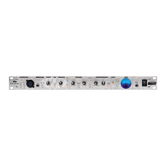
FACILITIES AND CONTROLS............................................................................ 3
MICROPHONE INPUT ........................................................................................ 3
1/4" TRS INPUT ................................................................................................... 4
PRE-AMP............................................................................................................... 4
HPF ......................................................................................................................... 4
MID SCOOP EQ .................................................................................................... 5
COMPRESSOR...................................................................................................... 5
LATENCY-FREE MONITORING........................................................................ 6
DIGITAL................................................................................................................. 6
LEVEL .................................................................................................................... 7
ADC EXT IN.......................................................................................................... 7
OPTIONAL DIGITAL OUTPUT.......................................................................... 7
DIGITAL OUTPUT INSTALLATION GUIDE .................................................... 8
FREQUENTLY ASKED QUESTIONS ............................................................... 10
TROUBLESHOOTING ....................................................................................... 11
CONTACTING US .............................................................................................. 11
SPECIFICATIONS................................................................................................ 12
FOCUSRITE DISTRIBUTORS........................................................................... 14
IMPORTANT SAFETY INSTRUCTIONS
Please read all of these instructions and save them for future reference. Follow all
warnings and instructions marked on the unit.
•
Do not obstruct air vents in the rear panel. Do not insert objects through any
apertures.
•
Do not use a damaged or frayed power cord.
•
Unplug the unit before cleaning. Clean with a damp cloth only. Do not spill liquid
on the unit.
•
Ensure adequate airflow around the unit to prevent overheating. We recommend
leaving a blank 1U panel above the unit to aid ventilation.
•
Unplug the unit and refer servicing to qualified service personnel under the
following conditions: If the power cord or plug is damaged; if liquid has entered
the unit; if the unit has been dropped or the case damaged; if the unit does not
operate normally or exhibits a distinct change in performance. Adjust only those
controls that are covered by the operating instructions.
•
Do not defeat the safety purpose of the polarised or grounding-type plug. A
polarised plug has two blades with one wider than the other. A grounding type
plug has two blades and a third grounding prong. The wider blade or the third
prong is provided for your safety. When the plug provided does not fit into your
outlet, consult an electrician for replacement of the obsolete outlet.
This unit is supplied with an external power supply dependant on the region in which
the TrakMaster Pro is purchased. To avoid the risk of fire, replace the mains fuse only
with the correct value fuse, as marked on the plug. The external power supply unit
contains no user serviceable parts. Refer all servicing to a qualified service engineer,
through the appropriate Focusrite dealer.
1
Advertisement
Table of Contents

Related Manuals for Focusrite TrakMaster Pro


Summary of Contents for Focusrite TrakMaster Pro
-
Page 1: Table Of Contents
TrakMaster Pro is purchased. To avoid the risk of fire, replace the mains fuse only with the correct value fuse, as marked on the plug. The external power supply unit contains no user serviceable parts. Refer all servicing to a qualified service engineer, through the appropriate Focusrite dealer. -
Page 2: Introduction
Focusrite Green range and features an extremely transparent sonic character with signal. With classic Focusrite analogue circuit design and a comprehensive digital very low distortion. It utilises the same full bandwidth philosophy of all Focusrite output option, TM Pro is the perfect partner for a digital audio workstation, making products, ensuring detail and clarity without obvious colouration. -
Page 3: Getting Started - A Quick Guide
GETTING STARTED – A QUICK GUIDE FACILITIES AND CONTROLS POWER 1. Ensure that nothing other than the mains supply is connected to your TrakMaster This switch turns the unit on. We recommend that the unit be powered up before Pro, then switch it on via the POWER switch on the right hand side of the unit. If connecting to any equipment that it is feeding, to avoid clicks or thumps, which may your unit is permanently connected to a patchbay, ensure audio is not being fed to any harm output devices. -
Page 4: 1/4" Trs Input
1/4" TRS INPUT With a MIC INPUT connected to the XLR connector (ensure nothing is connected to the 1/4" TRS input), the LEVEL control provides +13dB (fully anti-clockwise) to +60dB (fully clockwise) of gain. With a LINE INPUT connected to the 1/4" TRS connector, the gain is adjustable from -10dB (fully anti-clockwise) to +36dB (fully clockwise). -
Page 5: Mid Scoop Eq
MID SCOOP EQ COMPRESSOR The MID SCOOP EQ section allows you to cut a band of selectable frequency by up The COMPRESSOR acts like an automatic volume control, turning down the volume to 10dB. This can be useful for removing troublesome frequencies when recording of a signal if it gets too loud. -
Page 6: Latency-Free Monitoring
COMP SLOW ATTACK (switch) as the left hand channel). The stereo pair then becomes the INPUT signal, sent to the L and R channels of the headphones accordingly and the optional digital card for Engaging this switch selects a slower attack time, which allows more of the transient conversion to SPDIF format. -
Page 7: Level
This balanced (+4dBu) TRS jack connector on the rear panel allows an external mono source, from another Focusrite channel strip for example, to be fed into the TM Pro for... -
Page 8: Digital Output Installation Guide
EXT WORD CLOCK INPUT Top cover removal If an external word clock source is attached to this BNC connector, the TrakMaster Pro will attempt to synchronise to it. When the unit is correctly locked to the external clock Remove the 10 crosshead screws fixing the top cover to the top and sides of the source, the ADC LOCK LED in the DIGITAL section on the front panel will module. - Page 9 Installing digital card Place module on a flat clean surface with the bottom facing uppermost and offer the two crosshead screws supplied to the two countersunk holes in the base, using a The digital card is mounted in place using the digital connector fixings and the two small piece of adhesive tape to secure the head of the screw to the bottom surface plastic support pillars, which should be fitted to the module base using the two of the module.
-
Page 10: Frequently Asked Questions
• For 75 Low-Z operation, J1 should be left fitted, as supplied from factory. • For Professional use, J2 should be left fitted, as supplied from factory. • For Hi-Z operation, J1 should be removed. • For Consumer use, J2 should be removed. Replacing the Top Cover Selecting Word Clock Impedance The top cover should now be replaced using the 10 crosshead screws. -
Page 11: Troubleshooting
If you have any further questions about your TrakMaster Pro, or are continuing to • Is the power switched on? have difficulty, you can visit the support section at www.focusrite.com or email us for • Is the LEVEL set correctly? (See 'Facilities and Controls' section for details.) help at tech@focusrite.com. -
Page 12: Specifications
SPECIFICATIONS Mic Input Response Level Meter Gain = +13dB to +60dB Peak Level Moving Coil Meter Input impedance = 2.5k (150 in Lo Z mode) EIN = 126dB @ 60dB gain with 150 termination & 22Hz/22kHz filter -24dBFS to +2dBFS (-2dBu to +24dBu) THD+N @ min gain (+13dB) = 0.001% with 0dBu input &... - Page 13 Mid Scoop EQ EQ shape = peak Centre frequency = variable between 120Hz and 2kHz Cut (DEEP switch out) = -5dB Cut (DEEP switch in) = -10dB Q (DEEP switch out) = 0.7 Q (DEEP switch in) = 2 ADC Performance Sample Frequency = 44.1kHz, 48kHz, 88.2kHz &...
-
Page 14: Focusrite Distributors
Email: pro_brands@attrade.ru Email: nmk@emirates.net.ae Email: elfa@ozmail.com.au Email: info@newmusik.dk Grisby Music Srl Team 108 Focusrite Audio Engineering Ltd Klangfarbe GesmbH Alpha Audio Phone: +39 0 71 7211340 Phone: +65 748 9333 Phone: +44 (0) 1494 462246 Phone: +43 1545 1717 52...
Need help?
Do you have a question about the TrakMaster Pro and is the answer not in the manual?
Questions and answers