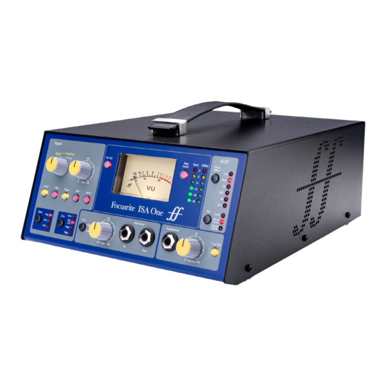
Focusrite ISA One Manual
Digital option installation
Hide thumbs
Also See for ISA One:
- Installation and user manual (8 pages) ,
- User manual (20 pages) ,
- User manual
Advertisement
Quick Links
ISA One & 430 MKII
Digital Option Installation
Digital Output Kit
The kit should contain:
DIGITAL OUTPUT
Qty
Description
1
Analogue to Digital converter card
4
Crosshead screws
DIGITAL OUTPUT
Tools required: -
No. 1 crosshead screwdriver, Pozihead preferred.
REMOVE THESE TWO SCREWS
WARNING!
THE MODULE SHOULD BE DISCONNECTED FROM THE AC POWER
REMOVE THESE TWO SCREWS
SUPPORT BRACKETS FOR ADC CARD
BEFORE ATTEMPTING TO CARRY OUT THE FOLLOWING INSTRUCTIONS.
4x SCREW HOLES FOR MOUNTING
SOCKET FOR
ADC USING 4x CROSSHEAD
ADC CABLE
SCREWS SUPPLIED IN KIT
ALLOW THE MODULE TO COOL BEFORE STARTING INSTALLATION OF
THE DIGITAL OPTION.
SUPPORT BRACKETS FOR ADC CARD
4x SCREW HOLES FOR MOUNTING
SOCKET FOR
J42
ADC USING 4x CROSSHEAD
ANTI-STATIC PRECAUTIONS SHOULD BE TAKEN WHEN HANDLING THE
ADC CABLE
SCREWS SUPPLIED IN KIT
ORIENTATION
CARD OUTSIDE OF ITS ANTI-STATIC BAG: ONLY HANDLE THE CARD BY
NOTCH
GRIPPING ITS EDGES AND AVOID TOUCHING ANY OF THE COMPONENT
PARTS OTHER THAN THE CABLE AND CONNECTORS. PLACE THE UNIT
J42
ON A FLAT, CLEAN SURFACE.
ORIENTATION
NOTCH
ISA 430 MKII Instructions
Removing the Top Cover
Remove the 11 crosshead screws fixing the top cover to the top and sides
of the ISA 430 MKII unit.
Removing the Digital Option Cover on the Rear Panel
The rear panel digital connector area is accessed by removing the rear
cover plate above the 'DIGITAL OUTPUT' labelling. The plate is removed by
removing the two crosshead screws shown below. Retain these screws for
securing the digital card in place later.
REAR PANEL
REAR PANEL
DIGITAL OUTPUT
DIGITAL OUTPUT
REMOVE THESE TWO SCREWS
Installing the Digital Option
REMOVE THESE TWO SCREWS
The digital card is mounted in place using the four supplied crosshead
TOP VIEW
screws and the two support brackets within the unit, as shown below.
SOCKET FOR
ADC CABLE
TOP VIEW
REAR PANEL
SOCKET FOR
ADC CABLE
REAR PANEL
ORIENTATION
NOTCH
ORIENTATION
NOTCH
SUPPORT BRACKETS FOR ADC CARD
4x SCREW HOLES FOR MOUNTING
ADC USING 4x CROSSHEAD
SCREWS SUPPLIED IN KIT
SUPPORT BRACKETS FOR ADC CARD
4x SCREW HOLES FOR MOUNTING
ADC USING 4x CROSSHEAD
SCREWS SUPPLIED IN KIT
J42
J42
Fitting the Card
Place the card into the unit with the cable pointing towards socket J42.
Rest the card on the brackets so that the four holes on the card line up
with the four holes on the bracket. Screw the card into place using the
SIDE VIEW
four crosshead screws and the two screws retained from the rear digital
option cover.
SIDE VIEW
TOP VIEW
REAR PANEL
TOP VIEW
REAR PANEL
Once the card has been secured into place, the digital card ribbon cable
can be connected to the socket on the ISA 430 MKII labelled J42. The
connector should be pressed firmly down in place to ensure a good
contact.
N.B. The cable has an orientation tab that should align with the
SIDE VIEW
orientation notch in the socket. If this is not correctly aligned, the cable
will not fit correctly – do not force it!
SIDE VIEW
Replacing the Top Cover
The top cover should now be replaced, using the 11 crosshead screws to
secure firmly to the chassis.
The installation is now complete and the unit can be reconnected to the
AC power.
Initialising the ISA 430 MKII Unit with the ADC fitted
The ISA 430 MKII recognises the installation of the digital card after you
have carried out the following step:
TOP VIEW
• Press and hold down any switch on the front of ISA 430 MKII whilst
powering up the unit. Once the front panel is illuminated, release the
REAR PANEL
TOP VIEW
switch.
REAR PANEL
The digital card will now be active. This is a one-time action. Once
initialised, the ISA 430 MKII will recognise the presence of the ADC each
time the unit is powered up.
Please refer to the full User Guide for digital card operation.
REAR PANEL
REAR PANEL
REPLACE SCREWS REMOVED
FROM REAR OPTION COVER
REPLACE SCREWS REMOVED
FROM REAR OPTION COVER
ATTACH CARD TO BRACKETS
USING 4x CROSSHEAD SCREWS
SUPPLIED IN KIT
ATTACH CARD TO BRACKETS
USING 4x CROSSHEAD SCREWS
SUPPLIED IN KIT
REAR PANEL
REAR PANEL
REPLACE SCREWS REMOVED
FROM REAR OPTION COVER
REPLACE SCREWS REMOVED
FROM REAR OPTION COVER
ATTACH CARD TO BRACKETS
USING 4x CROSSHEAD SCREWS
SUPPLIED IN KIT
ATTACH CARD TO BRACKETS
USING 4x CROSSHEAD SCREWS
Advertisement

Subscribe to Our Youtube Channel
Related Manuals for Focusrite ISA One


Summary of Contents for Focusrite ISA One
-
Page 1: Removing The Top Cover
ISA One & 430 MKII Fitting the Card Place the card into the unit with the cable pointing towards socket J42. EAR PANEL Digital Option Installation Rest the card on the brackets so that the four holes on the card line up with the four holes on the bracket. Screw the card into place using the SIDE VIEW REAR PANEL four crosshead screws and the two screws retained from the rear digital Digital Output Kit option cover. AR PANEL The kit should contain: DIGITAL OUTPUT SIDE VIEW Description REAR PANEL Analogue to Digital converter card Crosshead screws... - Page 2 NOTCH The installation is now complete and the unit can be reconnected to the J14A LATCHES ORIENTATION AC power. ADC CARD NOTCH J14A LATCHES Initialising the ISA One Unit with the ADC fitted The ISA One recognises the installation of the digital card after you have carried out the following step: • Press and hold down any switch on the front of ISA One whilst powering up the unit. Once the front panel is illuminated, release the switch. The digital card will now be active. This is a one-time action. Once initialised, the ISA One will recognise the presence of the ADC each time ATTACH CARD TO SUPPORT 3 SUPPORT LEDGES LEDGES USING 3 OF THE the unit is powered up.
Need help?
Do you have a question about the ISA One and is the answer not in the manual?
Questions and answers