Focusrite ISA One - Desktop Mic Preamp Manual
- Manual (2 pages) ,
- Installation and user manual (8 pages) ,
- User manual (20 pages)
Advertisement
- 1 About this User Guide
- 2 Box Contents
- 3 INTRODUCTION
- 4 ISA ONE CONTROLS AND FEATURES
- 5 PHYSICAL CHARACTERISTICS
- 6 Connector Pinouts
- 7 Preamp Input Impedance
- 8 Pro Tools Interfacing
- 9 External Clock Input – Unit Differences
- 10 PERFORMANCE AND SPECIFICATIONS
- 11 Troubleshooting
- 12 Documents / Resources
About this User Guide
This user guide applies to the ISA One mic pre. It provides information about installing and using the unit and how it can be connected into your system.
Also included is information relating to the optional ISA ADN2 A-D interface card, which will allow audio from the Mic pre to be added to a Dante network.
If you feel that additional information might be of assistance, be sure to consult the site: pro.focusrite.com/technical-support, which contains a comprehensive collection of common technical support queries.
Pro Tools® and Pro Tools | HDTM are trademarks or registered trademarks of Avid Technology, Inc. or its subsidiaries in the United States and/or other countries.
Dante® and Audinate® are registered trademark of Audinate Pty Ltd.
Box Contents
- ISA One unit
- AC power lead
- Safety information cut sheet
INTRODUCTION

The ISA One is a high quality transformer microphone preamplifier which can be used to record microphone, line-level or instrument sources. Microphone and line-level sources are connected to the rear panel, whilst an independent instrument input can be plugged directly into the front panel jack socket. A local amp or combo can also be connected to the front Amp output jack.
The front panel provides independent mic/line and instrument gain controls; settings for phantom power, phase and impedances for the mic and instrument inputs. The headphone output, with independent level control, can monitor either the selected channel signal or the stereo Cue input on the rear panel.
A traditional moving-coil VU and LED peak meters are provided, both with a trim control on the rear panel for calibration. The second LED peak meter indicates the level at the instrument DI or, when connected, the external input.
To maintain pristine Focusrite quality in the digital domain, an Analogue-to-Digital interface card may be fitted into the option slot on the rear panel. This provides access to a Dante network and features AES3, S/PDIF and ADAT signals.
Once the A-D card is installed, the internal/external clock sample rate and sync source can be selected using the switches on the front panel.
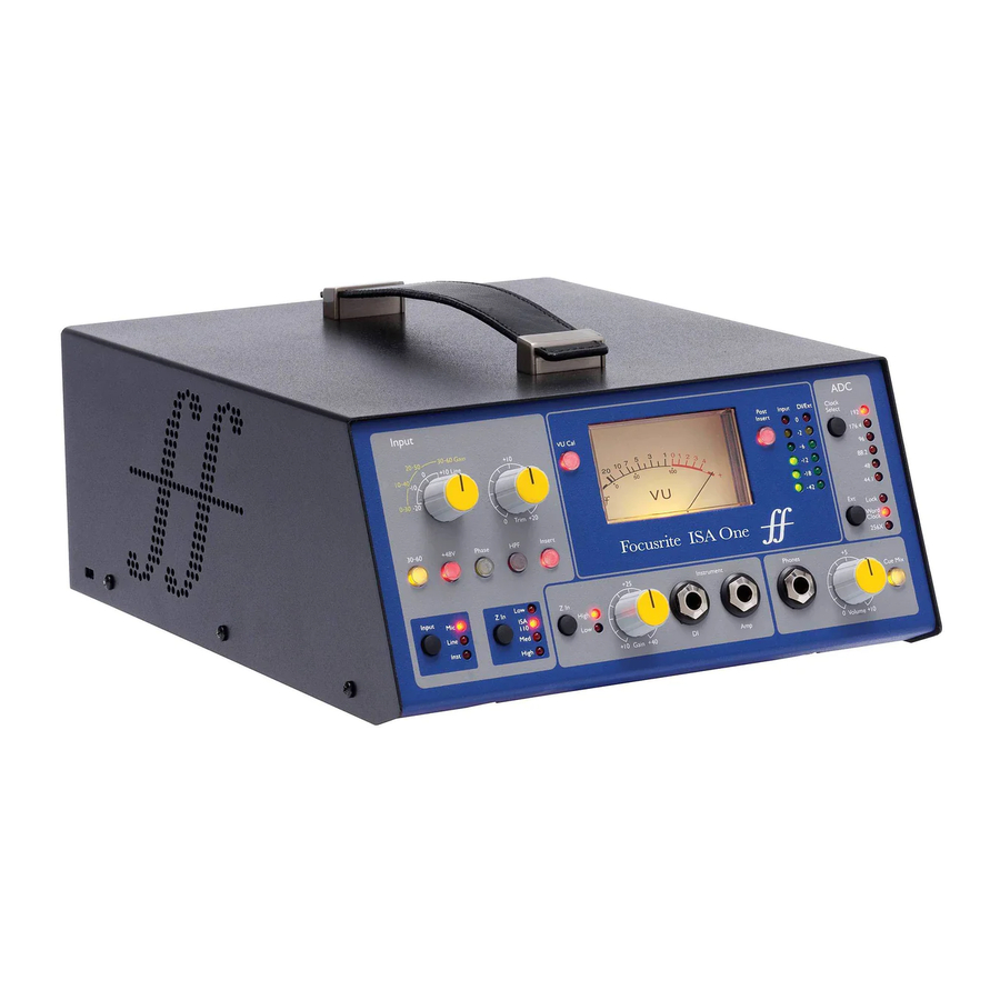
ISA ONE CONTROLS AND FEATURES
Front Panel

- 10 dB stepped Mic & Line Gain switch. Mic: 0-30 / 30-60 dB | Line: -20 +10 dB
- Selects the high mic input range (30-60 dB) on the Gain switch
- Trim pot: 0 +20 dB for the Mic & Line inputs
- Applies +48V phantom power to the mic input XLR
- Inverts polarity (Phase) of the selected input
- Applies the high-pass filter (HPF) to the selected input
- Switches the Insert return signal into the channel path
- Input source selection switch
- Z In (Input) selects the input impedance for the Mic input
- Z In (Instrument) selects the input impedance for the Instrument input
- Gain pot for the Instrument input
- 1/4" mono Jacks for the Instrument input (DI) with a parallel output to an Amp/combo. Also see rear panel DI output connector
- Enables the VU meter calibration mode.
- Moving-coil VU and
- peak-reading LED bargraph Input meters
- Toggles meters 14 & 15 to indicate the signal at Pre or Post the Insert point
- Peak-reading LED meter indicates the instrument input (DI) or the EXT IP (when connected)
- A-D option card clock and sync selection.
- 1/4" stereo Jack socket for Headphones
- Headphone volume pot
- Sends the stereo Cue Mix inputs (on the rear panel) to the headphones
Operation
Input Selection
The Input button selects the input source for the main channel path: Mic / Line / Instrument.
A 2nd audio path is available via the DI connector. See 'Instrument Input' below, and item 9
Mic Input Gain
The Gain switch adjusts the mic gain in 10 dB steps. Its range is either 0–30 dB or 30–60 dB when the 30–60 switch is pressed. An additional 0–20 dB of continuous gain adjustment is available using the Trim control.
To avoid an excessive jump in level, It is recommended that the stepped Gain switch is turned to minimum before pressing the 30-60 switch.
Before starting a recording, set the Trim control to near its centre position. This will allow for some gradual gain adjustment up or down without the use of the stepped control.
+48V
Pressing the +48V button applies phantom power to the Mic input XLR. This switch does not affect the Line or Instrument inputs.
If you are unsure whether your microphone requires phantom power please refer to its handbook. Certain microphones (most notably ribbon and unbalanced mics) could be damaged by applying phantom power.
Z In (Input Impedance – Mic)
With the Mic input selected, pressing the Z In button steps through the four transformer preamp input impedance options. The values are shown in the table.
| Low | 600 Ω |
| ISA 110 | 1.4 kΩ |
| Med | 2.4 kΩ |
| High | 6.8 kΩ |
Mic Impedance
For information on impedance selection see "Preamp Input Impedance".
The Line input impedance is fixed at 10 kΩ and is not affected by the Z In switch.
Line Input Gain
The Gain switch adjusts the gain between -20 dB and +10 dB in 10 dB steps. Continuous gain adjustment of up to 20 dB can be added using the Trim control.
Instrument Input (DI / Amp)

The Instrument input is via a standard 1/4" mono jack (DI) on the front panel. The level is set using the Gain control and is continuously adjustable from +10 dB to +40 dB.
The adjacent Amp Jack provides a parallel feed for connection to a guitar amplifier/combo.
A permanent line level feed of the instrument signal is provided on the DI O/P connector on the rear panel.
Z In (Input Impedance – Instrument)
Pressing the switch toggles between High (guitar pickups) and Low (vintage/high Z-out equipment) settings. The values are shown in the table.
| Low | 470 kΩ |
| High | 2.4 MΩ |
Instrument Impedance
Phase
Pressing Phase inverts the polarity of the selected input. This can be useful when multiple mics are used in close proximity (ie., on a drum kit).
Filter
Pressing the Filter button inserts the 18 dB/octave 75 Hz high-pass filter into channel path; it is applied to whichever input is selected.
The filter is useful for removing any unwanted low frequencies, eg., rumble transmitted through floor mounted mic stands, etc.
Insert
Pressing Insert places the Insert Return signal into the channel path before the Output connector, allowing the inclusion of external effects units.
The Insert Send is always available and is post the input Gain and Filter & Phase controls.
Phones/Cue Mix
Standard stereo headphones can be connected to the front panel 1/4" jack socket. The signal being sent to the headphones is determined by the status of the Cue Mix switch:
- Cue Mix Switch Off – The headphone feed will be a nonadjustable mono mix of two separate sources: (1); the selected input (Mic, Line or Inst) and (2); either the DI or the EXT I/P signal.
This, for example, allows a mic (via the rear panel) and a guitar (via the DI jack) / or a keyboard (via the Ext I/P jack) to be monitored simultaneously.
Note that if 'Inst' is selected as the input (with no Ext I/P jack) the instrument will be the only source heard - Cue Mix Switch On – The headphones will now monitor the Cue Mix Left and Right inputs on the rear panel in stereo. Changing input selection and/or inserting an Ext I/P jack will not affect the headphone source.
A-D Card Clock and Sync Switches

Clock select
Allows the user to select the internal sample frequency: 44.1kHz, 48kHz, 88.2kHz, 96kHz, 176.4kHz, or 192kHz.
Ext
Allows the ISA ADN2 A-D card to follow an external Word Clock source. Press the switch to toggle between standard and Dante clock.
Lock LED
Indicates that the unit is successfully synchronised to the external Word Clock.
On earlier ISA One units, the lock LED may flash under certain conditions. Please refer to "External Clock Input – Unit Differences" for additional information.
Metering
ISA One's front panel provides three level meters: a traditional moving-coil VU meter – which shows the average volume level, plus two peak-reading LED bargraphs – which indicate dBFS, ie., the level in dB, relative to maximum output (when the red '0' LED illuminates).

The VU meter and the left Input LED bargraph are linked and both indicate the main signal (the selected Input, post Gain & Filter) at the point set by the status of the Post Insert switch:
- Post Insert Switch Off – The VU and Input LEDs indicate the signal level at the Insert Send connector. This will also be the Main O/P when the Insert switch is off.
- Post Insert Switch On – The VU and Input LEDs now indicate the signal level at the Insert Return connector. This will also be the Main O/P when the Insert switch is on.
The right DI/Ext bargraph indicates the level at one of two different signal locations, determined by the presence of a jack at the rear Ext I/P socket:
- Ext I/P unused – The right LED meter indicates the level at the DI O/P connector.
- Ext I/P jack inserted – The right LED meter now indicates the level at the external input.
Metering the A-D Inputs
The two inputs to the A-D option card are fed from; Ch.1: the Main O/P; Ch.2: the Ext I/P.
With the Ext I/P jack connected – and the left LED meter indicating the Main O/P (see above) – the LED bargraphs will display both signals being sent to the A-D card inputs.
At default calibration, LED '0' indicates a signal level of 22 dBu, which is the maximum input level of the A-D card.
Meter Calibration
The calibration of the VU and LED meters can be adjusted using trim controls on the rear panel. Note that changes to the VU meter calibration will only take effect by pressing the VU Cal switch.
- VU Meter – The default VU meter lineup (VU Cal switch off) is 0 VU = 4 dBu.
With the VU Cal switch on, rotating the VU Meter Cal knob will set the value at between 0 VU = 11 dBu (fully anti-clockwise) and 0 VU = 26 dBu (fully clockwise), with 0 VU = 22 dBu at the centre detent position.
![]()
- LED Meters – The default setting of 0 dBFS = 22 dBu occurs when the knob is in its central detent position – to correspond with the maximum input level of the A-D card.
Rotating the Peak Meter Cal knob will set the value at between 0 dBFS = 15 dBu (fully anti-clockwise) and 0 dBFS = 26 dBu (fully clockwise).
![]()
Rear Panel

- Mains power switch.
- Standard IEC receptacle for AC mains. ISA One features a 'Universal' PSU, enabling it to operate on any supply voltage between 100 and 240 V AC
- Slot for ISA ADN2 analogue to digital conversion card. The card allows two audio signals from the ISA One to be added to a Dante network. It also provides AES3, S/PDIF and ADAT signals. See the following page for A-D card details
- Adjusts the VU meter '0' indication between 11 and 26 dBu. At the detent position the reading will be 22 dBu – which matches the maximum input level of the A-D card
The Cal control only takes effect when the front panel "VU Cal" button is pressed. When not pressed, VU '0' indicates a level of 4 dBu - Adjusts the LED meters reading at full scale between 15 and 26 dBu. At the detented position the reading will be 22 dBu
- Balanced 1/4" TRS Jack sockets for the Left and Right Cue Mix inputs
- Balanced 1/4" TRS Jack socket (Ext I/P) which feeds input 2 of the A-D option card
- Balanced 1/4" TRS Jack sockets for Insert Send and Return. The insert can be added into the channel path by pressing the front panel Insert switch
- XLR-3 male provides a Line-level output of the instrument signal (DI). The signal is post the instrument gain control and is always available irrespective of any switch selection
- XLR-3 male for the Main channel output – as selected by the front panel Input button. This output is linked internally to input 1 of the A-D option card
- Balanced 1/4" TRS jack and
- XLR-3 female connector for the Line input. The connectors are internally linked so must not be connected to different sources
- Balanced XLR-3 female connector for microphone input. Phantom power can be applied by pressing the +48V switch
A-D Option Card
The optional ISA ADN2 A-D card can be retrofitted to an ISA One at any time. Engineering experience is not required as the card can easily be installed by the user.
Note that the ISA One does not support the earlier ISA 2-Channel A-D card.
Once fitted, configuration of the card is carried out over the network using either RedNet Control or the Dante Controller software application.
The fitting instructions and network software applications are included with the A-D card option.

Word Clock – Input
Allows the card to be synchronised to an external Word Clock source via the BNC connector.
Word Clock – Output
Provides an output of the external Word Clock source connected at the "Word Clock In" BNC connector or, transmits the internal sample frequency of the A-D card.
- When the ISA One is following other units within a larger digital system, the Word Clock Out connector can be used to pass on the Word Clock signal to the next device.
- When the unit is not following another device and is in Internal Clock mode, the Word Clock Out connector outputs the sample frequency selected on the ISA One front panel.
Primary Network Port
Latching RJ45 connector for the Dante network. Use standard Cat 5e or Cat 6 network cable to connect the ISA ADN2 to a local Ethernet switch which is connected to the Dante network. Adjacent to the network sockets are LEDs which illuminate to indicate a valid network connection and network activity.
Secondary Network Port
Can be used as the Secondary Dante network connection where two independent Ethernet links are being used (Redundant mode), or as an additional port on an integral network switch on the primary network (Switched mode).
ADAT
2-channel ADAT optical output using standard TOSLINK connector.
S/PDIF I/O
2-channel digital interface on RCA (phono) connector.
AES3 Output
2-channel AES3 output on XLR-3 male connector.
See "Connector Pinouts" for connector pinouts. See "Pro Tools Interfacing" for Pro Tools interfacing information.
PHYSICAL CHARACTERISTICS

ISA One dimensions are illustrated in the diagram above. Allow for an additional 75mm [3"] behind the unit to allow for cable connections.
ISA One comes in a freestanding case fitted with a top-mounted carrying handle. It weighs 3.9 kg [8.6 lbs] and is equipped with rubber feet for table mounting.
ISA One generates little significant heat and is cooled by natural convection. Vents are provided at each side; ensure that when mounted close to other equipment these vents are not obstructed. Do not position the unit immediately above any other equipment which generates significant heat, for example, a power amplifier.
Note. The maximum operating environmental temperature is 40°C / 104°F.
Power Requirements
ISA One is mains powered and incorporates a 'Universal' power supply which can operate on any AC mains voltage from 100 V to 240 V. The AC connection is via a standard 3-pin IEC connector on the rear panel.
A mating IEC cable is supplied with each unit – this should be terminated with a mains plug of the correct type for your country.
Power consumption for ISA One is 35 W.
Please note that there are no fuses or other user-replaceable components of any type in any unit. Please refer all servicing issues to the Customer Support Team (see "Customer Support and Unit Servicing").
Connector Pinouts
Mic Input / Line Input
Connector: XLR-3 female
| Pin | Signal |
| 1 | Screen |
| 2 | Hot (+ve) |
| 3 | Cold (–ve) |
Main Output / DI Output
Connector: XLR-3 male
| Pin | Signal |
| 1 | Screen |
| 2 | Hot (+ve) |
| 3 | Cold (–ve) |
Line Input / Insert Send & Return
Ext Input / Cue Mic In Left & Right
Connector: Balanced (TRS) 1/4" Jack socket

| Pin | Signal |
| Tip | Hot (+ve) |
| Ring | Cold (–ve) |
| Sleeve | Ground |
Instrument Input / DI Output
Connector: Unbalanced (TS) 1/4" Jack socket

| Pin | Signal |
| Tip | Hot (+ve) |
| Sleeve | Ground |
ISA ADN2 Option Card:
AES3 Out
Connector: XLR-3 female
| Pin | Signal |
| 1 | Screen |
| 2 | Out Ch. 1&2 + |
| 3 | Out Ch. 1&2 - |
Network 1 & 2
Connector type: RJ-45 receptacle

| Pin | Cat 5/6 Core |
| 1 | White + Orange |
| 2 | Orange |
| 3 | White + Green |
| 4 | Blue |
| 5 | White + Blue |
| 6 | Green |
| 7 | White + Brown |
| 8 | Brown |
ADAT Optical Interface
Connector: TOSLINK
S/PDIF
Connector: RCA (Phono)
Word Clock In & Out
Connector: BNC 75Ω
Preamp Input Impedance
A major element of the sound of a mic pre is related to the interaction between the specific microphone being used and the type of mic preamp interface technology it is connected to. The main area in which this interaction has an effect is the level and frequency response of the microphone, as follows:
Level
Professional microphones tend to have low output impedances and so more level can be achieved by selecting the higher impedance positions of the ISA One mic preamp.
Frequency response
Microphones with defined presence peaks and tailored frequency responses can be further enhanced by choosing lower impedance settings. Choosing higher input impedance values will tend to emphasise the high frequency response of the microphone connected, allowing you to get improved ambient information and high end clarity – even from average-performance microphones. Various microphone/ISA One preamp impedance combinations can be tried to achieve the desired amount of colouration for the instrument or voice being recorded. To understand how to use the impedance selection creatively, it may be useful to read the following section on how the microphone output impedance and the mic preamp input impedance interact.
Impedance Setting – Quick Guide
In general the following selections will yield the following results:
High mic preamp impedance settings:
- Will generate more overall level
- Will tend to make low- and mid-frequency response of the microphone flatter
- Will improve high-frequency response of the microphone.
Low preamp impedance settings:
- Will reduce the microphone output level
- Will tend to emphasise the low- and mid-frequency presence peaks and resonant points of the microphone
Switchable Impedance – In Depth Explanation
Dynamic Moving Coil and Condenser Microphones
Almost all professional dynamic and condenser microphones are designed to have a relatively low nominal output impedance of between 150 Ω and 300 Ω when measured at 1 kHz. Microphones are designed to have such low output impedance because the following advantages result:
- They are less susceptible to noise pickup
- They can drive long cables without high frequency roll-off due to cable capacitance
The side-effect of having such low output impedance is that the mic preamp input impedance has a major effect on the output level of the microphone. Low preamp impedance loads down the microphone output voltage, and emphasizes any frequency-related variation in microphone output impedance. Matching the mic preamp resistance to the microphone output impedance (eg., making a preamp input impedance 200 Ω to match a 200 Ω microphone) still reduces the microphone output and signal to noise ratio by 6 dB, which is undesirable.
To minimise microphone loading, and to maximise signal to noise ratio, preamps have traditionally been designed to have an input impedance about ten times greater than the average microphone, around 1.2 kΩ to 2 kΩ. (The original ISA 110 preamp design followed this convention and has an input impedance of 1.4 kΩ at 1 kHz.) Input impedance settings greater than 2 kΩ tend to make the frequency-related variations of microphone outputs less significant than at low impedance settings. Therefore high input impedance settings yield a microphone performance that is flatter in the low and mid frequency areas and boosted in the high frequency area when compared to low impedance settings.
Ribbon Microphones
The impedance of a ribbon microphone is worthy of special mention, as this type of microphone is affected enormously by preamp impedance.
The ribbon impedance within this type of microphone is very low, around 0.2 Ω, and requires an output transformer to convert the low voltage it generates into a signal capable of being amplified by a preamp. The transformer uses a ratio of around 1:30 (primary: secondary) to increase the ribbon voltage to a useful level. This transformer ratio has the effect of increasing the output impedance of the mic to around 200 Ω at 1 kHz.
The transformer impedance, however, is very dependent upon frequency – it can almost double at some frequencies (known as the resonance point) and tends to roll off to very small values at low and high frequencies. Therefore, in common with dynamic and condenser microphones, the mic preamp input impedance has a significant effect on the signal level and frequency response of the ribbon microphone output transformer, and the associated 'sound quality' of the microphone. It is recommended that a mic preamp connected to a ribbon microphone should have an input impedance of at least 5 times the nominal microphone impedance.
For a ribbon microphone impedance of 30 Ω to 120 Ω, the input impedance of 600 Ω (Low) will work fine. For 120 Ω to 200 Ω ribbon microphones, the input impedance setting of 1.4 kΩ (ISA 110) is recommended.
Pro Tools Interfacing
- Analogue out to Pro Tools | HD

- Dante to Pro Tools | HD


External Clock Input – Unit Differences
The way in which ISA One responds to an external clock selection will vary slightly depending on the unit's revision.
On earlier units, the EXT clock input selections will include a 256X setting rather than the Dante Clock setting used on later units.
Front Panels Marked "256X"
The front panel EXT LED indicators will only follow the rate selected if the change is made using the front panel switch.
If a change to the external clock is made over the network, the front panel LED won't update, and the LOCK LED will start flashing.
Note that the unit will still operate correctly – it will still follow the RNC2 or the front panel switch selection – but it won't have updated the front panel LED indication.
When a change is made from the front panel, the unit will always toggle to whichever would be the next selection. For example: if the front panel is set to 48k, and the setting is changed to 44.1k via RNC2, 88.2k will still be the next sample rate selected by pressing the button on the front panel. This behaviour is the same for the sync source.
Front Panels Marked "Dante Clock"
On newer units the EXT LEDs will always indicate the correct setting whether changes are made from the front panel or via the network.
PERFORMANCE AND SPECIFICATIONS
| Microphone Inputs | |||
| All measurements taken at minimum gain, Z In: medium, unless otherwise stated. Measurements taken at the analogue outputs | |||
| Gain Range | 0 to 30 dB or 30 to 60 dB (with '30-60' switch enabled), in 10 dB steps, plus 0 to 20 dB of continuous trim | ||
| Maximum Input Level | +7 dBu | ||
| Input Impedance | Transformer balanced, Low: 600 Ω, ISA 110: 1.4 kΩ, Medium: 2.4 kΩ, High: 6.8 kΩ | ||
| Signal-to-Noise Ratio | 122 dB 'A'-Weighted (typical), maximum gain | ||
| Frequency Response | 20 Hz – 20 kHz ± 0.2 dB | 10 Hz – 110 kHz ± 1.5 dB | ||
| THD + N | -92 dB (0.0025%) @ -1 dBr | ||
| High-Pass Filter | 75 Hz knee frequency, 18 dB/octave | ||
| EIN | <-123 dBu 'A'-Weighted (typical), maximum gain | ||
| Common Mode Rejection Ratio | -93 dB @ 1kHz | ||
| Line Inputs | |||
| All measurements taken at minimum gain, Z In: Low, unless otherwise stated, RS = 50 Ω. Measurements taken at the analogue outputs | |||
| Gain Range | -20 to +10 dB in 10 dB steps, plus 0 to 20 dB continuous trim | ||
| Maximum Input Level | +25 dBu | ||
| Input Impedance | Electronically balanced 10 kΩ | ||
| Signal-to-Noise Ratio | 122 dB 'A'-Weighted (typical), maximum gain | ||
| Frequency Response | 20 Hz – 20 kHz ± 0.1 dB | 10 Hz – 122 kHz ± 3 dB unity gain | ||
| THD + N | -91 dB (0.0028%) @ -1 dBr | ||
| High-Pass Filter | 75 Hz knee frequency, 18 dB/octave | ||
| Common Mode Rejection Ratio | -65 dB @ 1 kHz | ||
| Instrument Inputs | |||
| All measurements taken at minimum gain, Z In: Low, unless otherwise stated, RS = 600 Ω. Measurements taken at the analogue outputs | |||
| Gain Range | +10 to +40 dB continuous, using Trim pot | ||
| Maximum Input Level | +18 dBu | ||
| Input Impedance | Low: 470 kHz, High: 2.4 MΩ | ||
| Signal-to-Noise Ratio | 100 dB 'A'-Weighted | ||
| Frequency Response | 20 Hz – 20 kHz ±0.1 dB | 10 Hz – 110 kHz ± 1.2 dB | ||
| THD + N | -83 dB (0.0071%) @ -1 dBFS | ||
| High-Pass Filter | 75 Hz knee frequency, 18 dB/octave | ||
| Connectivity | |||
| Front panel | |||
| Instrument input / Amp output | 2 x 1/4" mono jack | ||
| Rear Panel | |||
| Microphone input | XLR-3 female | ||
| Line level input Main output DI output | 1/4" balanced jack & XLR-3 female XLR-3 male XLR-3 male | ||
| Insert send Insert return | 1/4" balanced jack 1/4" balanced jack | ||
| Cue Mix inputs L & R | 2 x 1/4" balanced jack | ||
| Digital Card Slot | |||
| Compatible card | ISA ADN2 | ||
| Crosstalk | |||
| All measurements taken at minimum gain, Z In: Medium | |||
| Microphone Inputs | -60 dB, 20 Hz – 20 kHz | ||
| Line Inputs | -80 dB, 20 Hz – 20 kHz | ||
| Instrument Inputs | -80 dB, 20 Hz – 20 kHz | ||
| Dimensions | |||
| Height | 104mm / 4.1" | ||
| Width | 220mm / 8.7" | ||
| Depth | 290mm / 11.4" | ||
| Weight | |||
| Weight | 3.9 kg / 8.6 lbs | ||
| Power | |||
| PSU | 1 x Internal, 100 – 240 V, 50 / 60 Hz | ||
| Consumption | 35 W. | ||
| Environmental | |||
| Operating Temperature | 40°C / 104°F Maximum ambient operating temperature | ||
Focusrite Pro Warranty and Service
In the event of a Manufacturing Defect becoming evident in a product within 36 months from the date of the original purchase Focusrite will ensure that the product is repaired or replaced free of charge.
In the event that you need to contact the distributor regarding a warranty issue, or an out-of-warranty chargeable repair, please visit: pro.focusrite.com/rest-of-the-world
The distributor will then advise you of the appropriate procedure for resolving the warranty issue. In every case it will be necessary to provide a copy of the original invoice or store receipt to the distributor. In the event that you are unable to provide proof of purchase directly then you should contact the reseller from whom you purchased the product and attempt to obtain proof of purchase from them.
Registering Your Product
To access optional bundled software, please register your product at: focusrite.com/register
Customer Support and Unit Servicing
You can contact our Customer Support team free of charge:
Email: proaudiosupport@focusrite.com
Phone (UK): +44 (0)1494 836384
Phone (USA): +1 (310) 450-8494
Troubleshooting
If you are experiencing problems with your ISA One, we recommend that in the first instance, you visit our Support Help Centre at: pro.focusrite.com/help-centre

Documents / Resources
References
Technical Support | Focusrite Audio Engineering Ltd.
Rest of the World | Focusrite Audio Engineering Ltd.
![www.focusrite.com]() Please log in | Customer Portal
Please log in | Customer Portal
Download manual
Here you can download full pdf version of manual, it may contain additional safety instructions, warranty information, FCC rules, etc.
Advertisement


Need help?
Do you have a question about the ISA One and is the answer not in the manual?
Questions and answers