EverFocus EDSR400H Instruction Manual
Everfocus dvr instruction manual edsr400h
Hide thumbs
Also See for EDSR400H:
- Instruction manual (109 pages) ,
- Quick reference (4 pages) ,
- Instruction manual (65 pages)
Table of Contents
Advertisement
Quick Links
Advertisement
Table of Contents

Related Manuals for EverFocus EDSR400H


Summary of Contents for EverFocus EDSR400H
- Page 1 Volume Instruction Manual...
- Page 2 All rights reserved. No part of the contents of this manual may be reproduced or transmitted in any form or by any means without written permission of the Everfocus Electronics Corporation. QuickTime is a registered trademark of the Apple Computer, Inc. Windows is a registered trademark of the Microsoft Corporation in the United States and other countries.
-
Page 3: Table Of Contents
C H A P T E R Installation Basic Wiring Instructions Hard Disk Drive Installation Final Install Process C H A P T E R DVR Menu Setup Clock/Language Setting Menu Title Setting Menu Daylight Setting Menu Timer Setting Menu Normal Record Setting Menu... - Page 4 Gateway Address Virtual Ports Pre-Installation What type of Network Connection Simple One to One Connection Direct High Speed Modem Connection Router or LAN Connection C H A P T E R Linksys Port Forwarding Dynamic DNS C H A P T E R D-Link Port Forwarding Dynamic DNS C H A P T E R...
-
Page 5: Product Overview
E V E R F O C U S E L E C T R O N I C S Product Overview DVRs are the industry’s first full-featured digital video recorder designed specifically for use within the security industry. The Digital Video Recorder incorporates all the benefits of digital video recording, is simple to install, and operates just like a VCR. -
Page 6: Specifications
E V E R F O C U S E L E C T R O N I C S Specifications Video Format NTSC/PAL Video Input 4 camera inputs (BNC),1Vp-p/75ohm Video Output 1 BNC video out (1Vp-p/75 ohm) for Main Monitor 1 BNC video out (1Vp-p/75 ohm) for CALL Monitor 4 video out (1Vp-p/75ohm)for looping Video Compression... -
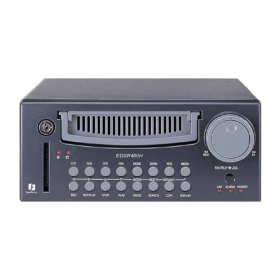
Page 7: Front Panel Keys
E V E R F O C U S E L E C T R O N I C S Front Panel Keypads Keys: CH1 ~CH4: Press channel key (1~4) to display the video image in full screen format for the channel specified. MODE: Press to switch between Picture-In-Picture and Quad modes. - Page 8 Display Date/Time and Titles HDD KEY: Turning this key to the lock position will activate the Hard Drive for recording and keep it securely locked into the DVR. Hard Disk Tray: Hard Disk holder for HDD. Shuttle and Jog Dial Shuttle : In Playback mode, turn the shuttle dial can fast forward/rewind the picture.
-
Page 9: Back Panel Connections
E V E R F O C U S E L E C T R O N I C S Back Panel Connections POWER Main Power plug: Connect the DC12~24V power source to Adapter for AC100~240V. AUDIO Audio IN: Audio input for recording. Audio OUT: Audio output can be set to “ON”... - Page 10 E V E R F O C U S E L E C T R O N I C S MONITOR MAIN MONITOR: This connector is used for the Main monitor display, a number of different display modes may be selected for viewing. This output must be used to display the menu settings.
- Page 11 E V E R F O C U S E L E C T R O N I C S C O R P O R A T I O N RS232 RS232 connector: Connect D-Sub 9 pin connector to RS232 port for remote control.
-
Page 12: Chapter
E V E R F O C U S E L E C T R O N I C S Installation The installations described below should be made by qualified service personnel or system installers. Please refer to the following diagram for the basic wiring connections. Please note: Monitors and Cameras must be purchased separately. -
Page 13: Basic Wiring Instructions
E V E R F O C U S E L E C T R O N I C S Basic Wiring Instructions Please refer to diagram 1 on page 9 to assist you with this portion of the installation. Power: Connect the power source or adapter into the power socket shown in diagram 1. -
Page 14: Hard Disk Drive Installation
Once you have completed the basic wiring installation and the hard disk drive installation you are read to turn on the DVR. Simply plug the power source you installed earlier. The POWER LED lights will light up if power is normal. The next step is to set up the menu options for the DVR. -
Page 15: Chapter
E V E R F O C U S E L E C T R O N I C S DVR Menu Setup Assuming you have completed the first two chapters of this manual. You are now ready to begin setting up the digital video recorder menu. To begin this process press the MENU key. -
Page 16: Clock/Language Setting Menu
Date: This field represents the current date on the DVR. To change this, simply use the arrow keys on the DVR which also represent the channel 1- 4 keys (These are the top four buttons). Use the up and down arrow keys to make your selection. - Page 17 Please note: New firmware versions are available for download from our ftp site. ftp://everfocus.dyndns.org/ firmware upgrade instructions) Release Date: This field represents the date the firmware was released. C O R P O R A T I O N...
-
Page 18: Title Setting Menu
To change this, simply use the arrow keys on the DVR which also represent the channel 1-4 keys (These are the top four buttons). Use the up and down arrow keys to make your selection. -
Page 19: Daylight Setting Menu
Daylight saving: This field is to turn the daylight savings function on or off. To change this, simply use the arrow keys on the DVR which also represent the channel 1-4 keys (These are the top four buttons). Use the up and down arrow keys to make your selection. - Page 20 E V E R F O C U S E L E C T R O N I C S The third field is set to “March”. This signifies the month in which the daylight savings time will occur. Your options are: Jan through Dec. Use the up and down arrow keys to make your selection.
-
Page 21: Timer Setting Menu
DLY option. To change this, simply use the arrow keys on the DVR which also represent the channel 1-4 keys (These are the top four buttons). Use the up and down arrow keys to make your selection. - Page 22 Set: This field is used to turn the timer recording on or off. To change this, simply use the arrow keys on the DVR which also represent the channel 1- 4 keys (These are the top four buttons). Use the up and down arrow keys to make your selection.
-
Page 23: Normal Record Setting Menu
Speed: This field represents the speed at which the recorder will be recording all the time. To change this, simply use the arrow keys on the DVR which also represent the channel 1-4 keys (These are the top four buttons). Use the up and down arrow keys to make your selection. - Page 24 E L E C T R O N I C S High Superior To change this, simply use the arrow keys on the DVR which also represent the channel 1-4 keys (These are the top four buttons). Use the up and down arrow keys to make your selection.
-
Page 25: Alarm Record Setting Menu
Default from the factory is set to on. To change this, simply use the arrow keys on the DVR which also represent the channel 1-4 keys (These are the top four buttons). Use the up and down arrow keys to make your selection. - Page 26 Normally Open circuit you would set the alarm type to N.O. To change this, simply use the arrow keys on the DVR which also represent the channel 1-4 keys (These are the top four buttons). Use the up and down arrow keys to make your selection.
- Page 27 Recording Speed: This option is to set the speed of the pre-alarm recording. To change this, simply use the arrow keys on the DVR which also represent the channel 1-4 keys (These are the top four buttons). Use the up and down arrow keys to make your selection.
-
Page 28: Buzzer Setting Menu
Use the up and down arrow keys to make your selection. Record-In: This option is to turn the buzzer on or off when the DVR is in record mode. To change this, simply use the arrow keys on the DVR which also represent the channel 1-4 keys (These are the top four buttons). - Page 29 Disk Full: This field is to turn the buzzer on or off when the Hard Disk Drive is full. To change this, simply use the arrow keys on the DVR which also represent the channel 1-4 keys (These are the top four buttons). Use the up and down arrow keys to make your selection.
-
Page 30: Archive Setting Menu
DVR is in record mode. The time stamp will appear when archiving through the network or to a Compact Flash card. To change this, simply use the arrow keys on the DVR which also represent the channel 1-4 keys C O R P O R A T I O N... - Page 31 You can set the time position either on top or bottom. The default is set to top. To change this, simply use the arrow keys on the DVR which also represent the channel 1-4 keys (These are the top four buttons). Use the up and down arrow keys to make your selection.
-
Page 32: Network Setting Menu
DVR. In the Network Setting Menu the following fields are defined as follows: IP Address: This field is to set a static IP Address for the DVR. A static IP address is an IP address whose value does not change. EverFocus suggest using a static IP address. - Page 33 1-4 keys (These are the top four buttons). Use the up and down arrow keys to make your selection. Gateway: This field is to set the gateway for your network so the DVR will be recognized within the network. An example of this is provided within the DVR we use to test the machine within our own network.
-
Page 34: Sequence Setting Menu
0 to 99 seconds. To change this, simply use the arrow keys on the DVR which also represent the channel 1-4 keys (These are the top four buttons). Use the up and down arrow keys to make your selection. - Page 35 0 to 99 seconds. To change this, simply use the arrow keys on the DVR which also represent the channel 1-4 keys (These are the top four buttons). Use the up and down arrow keys to make your selection.
-
Page 36: Rs232/Rs485 Setting Menu
RS232 Stop Bit: This field is to set the stop bit for the RS232 connection. There are two different stop bits, 1 or 2. The default in the DVR is set to 1. To change this, simply use the arrow keys on the DVR which also represent the channel 1-4 keys (These are the top four buttons). - Page 37 RS485 Stop Bit: This field is to set the stop bit for the RS485 connection. There are two different stop bits, 1 or 2. The default in the DVR is set to 1. To change this, simply use the arrow keys on the DVR which also represent the channel 1-4 keys (These are the top four buttons).
- Page 38 RS232/RS485 connection. There are two ID codes for the DVR: 001 or 002. The default is set to 001. To change this, simply use the arrow keys on the DVR which also represent the channel 1-4 keys (These are the top four buttons).
-
Page 39: Motion Record Setting Menu
To change this, simply use the arrow keys on the DVR which also represent the channel 1-4 keys (These are the top four buttons). Use the up and down arrow keys to make your selection. - Page 40 Manual Edit: This field represents manual editing of each camera for motion. To change this, simply use the arrow keys on the DVR which also represent the channel 1-4 keys (These are the top four buttons). Use the up and down arrow keys to make your selection. Once you have chosen the channel you would like to manually edit, press the ENTER button.
-
Page 41: Menu Button
E V E R F O C U S E L E C T R O N I C S Diagram 14 shows a screen shot of the manually edit screen. Use the arrow buttons to move through the squares. Initially all the squares are pink in color signifying that these squares are set up to pick up motion. -
Page 42: Chapter
This option can be turned on or off. The default is set to on. To change this, simply use the arrow keys on the DVR which also represent the channel 1-4 keys (These are the top four buttons). - Page 43 The default is set to No. If you would like to enable the password change this option to yes. To change this, simply use the arrow keys on the DVR which also represent the channel 1-4 keys (These are the top four buttons).
-
Page 44: Recording Overview
E L E C T R O N I C S Recording Overview Before continuing please be sure to have reviewed DVR Menu Setup (Chapter 3). You are now ready to begin setting up the machine for normal recording. This chapter will show you how to setup the recorder for basic recording. -
Page 45: Timer Recording Setup
Use the jog dial after completing the previous step and go to Timer Record Setting menu (See Page 17). Setup a timer for your application and exit the menu by pressing the Menu button. Once you have exited the menu the DVR will go into record mode. -
Page 46: Motion Recording Setup
Exit the menu by pressing the Menu button. Once you have exited the menu if motion is occurring the DVR will go into record mode. Make sure you press the record button if not recording or if after motion has stopped the record light has gone off. -
Page 47: Chapter
E L E C T R O N I C S To stop recording simply press the Stop button. Please Note: When the Hard Drive is full, the DVR will either stop recording automatically or overwrite from the beginning of the hard drive. - Page 48 Diagram 21 To stop recording simply press the Stop button. Please Note: When the Hard Drive is full, the DVR will either stop recording automatically or overwrite from the beginning of the hard drive. This is all dependent on what was set in the normal record setting (see...
-
Page 49: Playback Overview
Menu button. Go to Either Timer Setting Menu or Motion Record Setting menu and turn them off. Once you have stopped any type of recording on the DVR you are ready to do playback. Pressing the play button will set the recorder into playback mode and play the last segment recorded. -
Page 50: Search Playback
If the menu pops up when you press the stop button. This usually means you have either the DVR is in Timer record or Motion record. Log into the DVR menu by pressing the Menu button. Go to Either Timer Setting Menu or Motion Record Setting menu and turn them off. -
Page 51: Alarm List Playback
If the menu pops up when you press the stop button. This usually means you have either the DVR is in Timer record or Motion record. Log into the DVR menu by pressing the Menu button. Go to Either Timer Setting Menu or Motion Record Setting menu and turn them off. -
Page 52: Chapter
If the menu pops up when you press the stop button. This usually means you have either the DVR is in Timer record or Motion record. Log into the DVR menu by pressing the Menu button. Go to Either Timer Setting Menu or Motion Record Setting menu and turn them off. - Page 53 E V E R F O C U S E L E C T R O N I C S Use the up and down arrow keys to select Date/Time and press the enter key. Diagram 27 illustrates what the Date/Time field may look like. Use the up and down arrow keys to enter a date and time you want to playback, highlight search, and press the enter key.
-
Page 54: Copying Video
Before continuing please be sure to have reviewed the preceding chapters. You are now ready to copy an image or video from the DVR. This chapter will show you how to copy a still image or movie from the recorder. -
Page 55: Copy As A Mov File
E V E R F O C U S E L E C T R O N I C S You will then see “Copying …” on the screen while it is copying to the flash card. When it has finished copying will disappear from the screen. Diagram 28 The image on the Compact flash card will be stored as a jpeg file. -
Page 56: Other Archiving Methods
E V E R F O C U S E L E C T R O N I C S To exit press the stop button. The video is now stored on the Compact flash card as a MOV file. This type of file can be played using QuickTime video player. -
Page 57: Chapter
E L E C T R O N I C S Audio Overview This chapter will try to give you details on how to setup audio on the DVR. Before we begin the process of connecting audio to your digital recorder we should have the following items. -
Page 58: Chapter
Copy the .HEX to CF card using the Compact Flash reader that came with your DVR (from a computer). Please Note: Lexar Compact Flash Cards are not compatible with Everfocus digital recorders. Everfocus suggests using Sandisk or Kingston Compact Flash Cards. - Page 59 Next to System Upgrade you will notice it say "Reading...then Programming...then Success..." Once you have read success log out of the menu by pressing the menu button twice. Then turn the power on the DVR off and turn it back on.
-
Page 60: Networking Overview
This chapter will try to give you a detailed instruction on how to network the DVR. Before we begin the process of networking your digital recorder we should have a working knowledge of what a network is and how it works. This will be a helpful in completing the networking process. -
Page 61: Gateway Address
For example, some Web sites a person visits on the Internet use a URL like the following: http://www.everfocus.com:8100/ In this example, the number 8100 refers to the port number used by the Web browser to connect to the Web server. Normally, a Web site uses port number 80 and this number need not be included with the URL (although it can be). -
Page 62: Pre-Installation
That way, you can host a website, email server, or other type of server connection. Everfocus suggest using a static IP address. If your Internet provider does not offer a static IP address you have the option to use a dynamic IP address. -
Page 63: What Type Of Network Connection
What type of DVR are you installing? Everfocus EDR series: EDR 400, 1600 or 1680 Everfocus EDSR series: EDSR 110, 400H, 400M, 400, 900, or 1600 What Type of Network Connection do you have? Everfocus DVR’s can operate using three distinct types of networking connections. -
Page 64: Simple One To One Connection
Now Log into the Everfocus DVR menu and using the jog dial from the previous chapter go to the Network Setting Menu. (See page 28 for more... - Page 65 E L E C T R O N I C S C O R P O R A T I O N Assign an IP address of 192.168.001.003 to the DVR, a Subnet mask of 255.255.255.000, and a default gateway of 192.168.001.001.
- Page 66 E V E R F O C U S E L E C T R O N I C S C O R P O R A T I O N...
- Page 67 E V E R F O C U S E L E C T R O N I C S C O R P O R A T I O N...
- Page 68 E V E R F O C U S E L E C T R O N I C S C O R P O R A T I O N...
- Page 69 C O R P O R A T I O N Once you have reached this point click ok and restart both the computer and the digital recorder. To access the DVR from the computer simply open Internet Explorer and in the address bar type: http://192.168.1.3...
-
Page 70: Direct High Speed Modem Connection
E V E R F O C U S E L E C T R O N I C S Direct High Speed Modem Connection Internet Straight Through Ethernet Cable Pin outs: The Diagram below shows the pin configurations for a straight cable. Connection Procedure: The First step is to purchase or make a straight through cable. - Page 71 E V E R F O C U S E L E C T R O N I C S Now Log into the Everfocus DVR menu and using the jog dial from the previous chapter go to the Network Setting Menu. (See page 28 for more...
-
Page 72: Router Or Lan Connection
E V E R F O C U S E L E C T R O N I C S Router or LAN Connection Internet Cat 5 Straight Through Cable Straight Through Ethernet Cable Pin outs: The Diagram below shows the pin configurations for a straight cable. Connection Procedure: The First step is to purchase or make a straight through cable. - Page 73 Once you have a straight through cable plug one end into the LAN port on the back of the recorder and the other into the router. Now Log into the Everfocus DVR menu and using the jog dial from the previous chapter go to the Network Setting Menu. (See page 28 for more...
- Page 74 EDSR Ports to open: 80, 1111, 2222, 3333, 4444, 6666 Please Note: If your Internet service provider blocks port 80 you may use a different port to access the DVR through the routers UPNP forwarding (Linksys feature) or Virtual Server (D-Link feature).
-
Page 75: C H A P T E
E V E R F O C U S E L E C T R O N I C S Linksys Port Forwarding This chapter will cover a few simple configurations for the Linksys router. Please understand we do not support this product and will not give tech support on it. - Page 76 E V E R F O C U S E L E C T R O N I C S The first screen that appears displays the Setup tab. This allows you to change the Router's general settings. Change these settings as described here and click the Save Settings button to apply your changes or Cancel Changes to cancel your changes.
- Page 77 Change these settings as described here and click the Save Settings button to apply your changes or Cancel Changes to cancel your changes. Example: DVR 80 to 80 Both DVR 1111 to 1111 Both DVR 2222 to 2222 Both C O R P O R A T I O N 192.168.1.50 Enable 192.168.1.50...
- Page 78 E V E R F O C U S E L E C T R O N I C S DVR 3333 to 3333 Both DVR 4444 to 4444 Both DVR 6666 to 6666 Both DVR 1600 to 1600 Both The next step is to open ports within your router.
-
Page 79: Dynamic Dns
Example: DVR 8100 DVR 8100 UDP 80 To access the DVR from a computer simply open Internet Explorer and in the address bar type: http:// IP address of your internet service provider: 8100 Dynamic DNS The Router offers a Dynamic Domain Name System (DDNS) feature. DDNS lets you assign a fixed host and domain name to a dynamic Internet IP address. - Page 80 E V E R F O C U S E L E C T R O N I C S C O R P O R A T I O N DDNS Service - From this pull-down menu, enter the DDNS service with which you have membership.
-
Page 81: D-Link Port Forwarding
E V E R F O C U S E L E C T R O N I C S C O R P O R A T I O N Chapter D-Link Port Forwarding This chapter will cover a few simple configurations for the D-Link router. Please understand we do not support this product and will not give tech support on it. - Page 82 E V E R F O C U S E L E C T R O N I C S The next step is to open ports within your router. Go to Virtual Server in the router. Example1: Protocol Type - The protocol used for the virtual service.
- Page 83 Private Port: 80 Public Port: 8100 Schedule: always To access the DVR from a computer simply open Internet Explorer and in the address bar type: http:// IP address of your internet service provider: 8100 C O R P O R A T I O N...
-
Page 84: Dynamic Dns
Once you have enabled it enter the server address of DynDNS.org: members.dyndns.org Then enter the hostname you created with DynDNS.org Example: Everfocus.homeip.net Then enter the username and password you use to log into DynDNS.org C O R P O R A T I O N... - Page 85 E V E R F O C U S E L E C T R O N I C S C O R P O R A T I O N...
-
Page 86: C H A P T E
E V E R F O C U S E L E C T R O N I C S DDNS This chapter will cover a few simple configurations for setting up DDNS. Please understand we do not support this product and will not give tech support on it. - Page 87 Add Host link right next to Dynamic DNS. The next step is to add a host name with an extension. Example: Everfocus.homeip.net The IP address should already be entered for you. All you have to do is click add host and you are done registering DDNS.
- Page 88 E L E C T R O N I C S C O R P O R A T I O N To access the DVR from a computer simply open Internet Explorer and in the address bar type: http:// The DDNS you created example everfocu.homeip.net...
-
Page 89: C H A P T E
E L E C T R O N I C S Viewing through Internet Explorer To access the DVR from a computer simply open Internet Explorer and in the address bar type: http:// (LAN or IP address of your internet service provider) The digital video login page will appear on the screen similar to the one shown above. - Page 90 E V E R F O C U S E L E C T R O N I C S C O R P O R A T I O N Then click on the submit button and you will be logged into your recorder.
- Page 91 E V E R F O C U S E L E C T R O N I C S C O R P O R A T I O N...
- Page 92 E V E R F O C U S E L E C T R O N I C S C O R P O R A T I O N Please Note: If any icon is grayed, it means that particular function is not accessible.
-
Page 93: C H A P T E
E V E R F O C U S E L E C T R O N I C S Interface Specifications This Digital Video Recorder may be controlled by a computer or a terminal via the standard D-SUB 9-pin RS-232 connector. D-SUB 9-pin connector specifications: The pin assignment of the 9-pin D-SUB connector C O R P O R A T I O N... -
Page 94: Transmission Setting
9600 baud. Please refer to RS232/RS485 Setting Menu on page 32 for details. Remote Control Protocol A computer can be used to control the DVR by sending the packet as follows. C O R P O R A T I O N... -
Page 97: Appendix
Appendix Remote Control... -
Page 98: Appendix
Appendix Time Lapse Mode Recording Time... -
Page 100: Appendix
Appendix Alarm Board Configuration... -
Page 103: Motion Setting Menu
IPS set for Alarm prior to the Alarm or Motion activity. Lastly, you must make sure the REC light is continually illuminated. **Explanation: The DVR will record at a lower IPS when there is no motion, which will conserve HDD space. When motion is detected by a camera, the DVR will record at a higher IPS. - Page 104 The next step is to verify the recorder is getting the correct amount of power. There is no display coming from one of the channels on the DVR? The first step is to verify is the problem coming from the recorder or the camera.
- Page 105 www.tzo.com. (Preferred routers: Linksys BEFSR41 V3 or DLINK DI624 or any router that offers DDNS.
Need help?
Do you have a question about the EDSR400H and is the answer not in the manual?
Questions and answers