
Related Manuals for EverFocus EDSR400M


Summary of Contents for EverFocus EDSR400M
- Page 1 INSTRUCTION MANUAL Mobile Digital 4-Channel Video Recorder About this manual Before installing and using this unit, please read this Manual carefully. Be sure to keep it handy for later reference. EDSR400M V1.0...
-
Page 2: Safety Warning
WARNING TO REDUCE RISK OF FIRE OR ELECTRIC SHOCK, DO NOT EXPOSE THIS APPLIANCE TO RAIN OR MOISTURE CAUTION DO NOT REMOVE COVER. NO USER SERVICEABLE PARTS INSIDE. REFER SERVICING TO QUALIFIED SERVICE PERSONNEL. Note: This equipment has been tested and found to comply with the limits for a Class A digital device, The changes or modifications not expressly approved by the party responsible for compliance could void the user's authority to operate the equipment. -
Page 3: Safety Precautions
Do not operate the appliance beyond its specified temperature, humidity or power source ratings. Do not use the appliance in an extreme environment where high temperature or high humidity exists. Use the appliance at temperature within indoor type DVR for 0 C ~ +40 C / outdoor... - Page 4 Safety Precautions The lightning flash with an arrowhead symbol, within an equilateral triangle, is intended to alert the user to the presence of uninsulated ” dangerous voltage” within the product’s enclosure that may be of sufficient magnitude to constitute a risk of electric shock to persons The exclamation point within an equilateral triangle is intended to alert the user to presence of important operating...
-
Page 5: Important Safeguards
Important Safeguards Important Safeguards Read Instruction---All the safety and operating instructions should be read before the init is operated Retain Instructions---The safety and operating instructions should be retained for future reference. Heed Warnings—All warnings on the unit and in the operating instructions should be adhered to. Follow Instructions—All operating and use instructions should be followed Cleaning—Unplug the unit from the outlet before cleaning. - Page 6 The EP2026A is equipped with electronic surge protection (up to 470V) to help protect the unit from damage. It is advised to operate the DVR while the car is running to minimize the power drain on the vehicle battery. Inspect the vehicle battery prior to installation to ensure maximum performance of your DVR.
- Page 7 Quick Install Guide The DVR can be mounted horizontally (suspend or support mounted). Support EDSR400M Interface Show all the possible ways to mount the DVR. Use the two Z-brackets supplied to mount it in any ways shown. EDSR400M Support EDSR400M...
- Page 8 Front of bulkhead-horizontal mount Beside deriver seat-horizontal mount Caution: Do not install the DVR on the floor or on the transmission access hatch. These locations have the highest levels of vibration and may be subject to water damage. Quick Install Guide...
- Page 9 Possible Installation Locations Inside the Automobile Vehicle: TOYOTA CAMRY Glove box (inside or underneath) Drive seat ( between seat and wall) Show the wiring on the wiring harness that connects to the electrical system. Car body Vehicle battery (+12V or +24V) Generator Quick Install Guide Passenger seat (underneath)
- Page 10 Quick Install Guide Truck Possible Installation Locations Inside the Automobile Vehicle: Glove box (inside or underneath) Drive seat ( between seat and wall) or Passenger seat (underneath) ( Suggest user use “ support” for mounting option) Show the wiring on the wiring harness that connects to the electrical system. Vehicle body Car body On/Off switch...
- Page 11 Installing the Camera(s) and Monitor The DVR is typically connected to one camera installed inside the car. Other camera(s) can also be installed in different location(for example, use the waterproof camera to the outside of vehicle ). For installation procedure, refer to the guide that came with the camera(s) you purchased.
- Page 12 Quick Install Guide Installing the Hard Drive As following are the figure for the 3.5” and 2.5” HDD. Figure shows 3.5“ HDD Figure shows 2.5“ HDD...
-
Page 13: Table Of Contents
1. Product Overview……….…...……………………………………………………………………… 1 ………...…………….….…………………………………….…………..……………….……1 Feature 1.2 Specifications…………….…...………….………………….……………..……….…….…………………………………..2 2. Front & Rear Panels………...…….………………………………………..………………………..3 3. Back Panel Connections…….………...……………………………………..……………………..5 4. System Connection…...………………………...…………………………..…………….………...8 4.1 Before Installation……..………………………………………………..……………………………..…………8 4.2 Basic Connection ……………………………………………………………………………………………………..……………… 5. Installation………...………………………………………………..……………….….…………...10 6. Menu………...……………….……………………………………..…………………………………11 Clock/Language Setup Menu…………………………………………….………………………...…...……13 6.2 Title Setting Menu……………………………………………………………………………………………..14 6.3 Daylight Setting Menu…………………………….……………………………………………………………15 6.4 Timer Setting Menu………………………………………………………………………………….…………17 6.5 Normal Setting Menu…………………………………………………………………………………….……18 6.6 Alarm Record Setting Menu………………………………………………………………………………...…19... - Page 14 Table of Contents 10. Interface Specifications……..………...………………………………………………………44 10.1 Transmission setting……..……………………………..………………………….…………………………………..44 10.2 Remote Control Protocol…………………………………..………………………………………………………..…45 11. Remote Controller………….…….……………………………………………………….……49 12. Appendix-A/Time Lapse Mode Recording Time…….……..…………………………..…50 12.1 Recording with and 80 GB HDD…..…………...………………….…………………………………………………..50 12.2 Recording with and 160 GB HDD…………..………………………………………………………………………….51 13.View from Internet/Intranet……………………………………………………………………..52...
-
Page 15: Product Overview
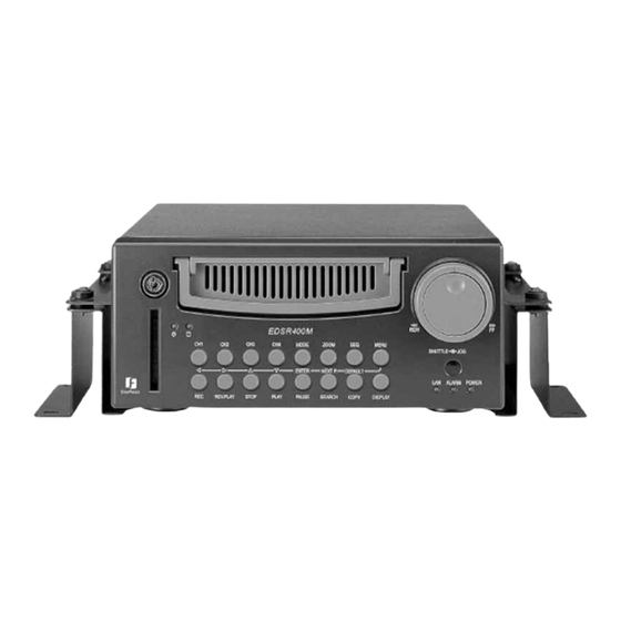
The EDSR400M is ideal for use in bused, cars, police cruisers, or any application requiring a rugged digital recorder. Video and audio can be recorded at speeds up to 60/50 fields per second (NTSC/PAL), and can be replayed instantly when the touch of a button. -
Page 16: Specifications
1.2 Specifications Video Input Video Output Video Compression Recording Resolution CompactFlash Memory Alarm Input Alarm Output Video Display Video Loss Detection Ethernet Event Log Hard Disk Storage Recording Mode Recording Rate Playback Rate Playback Search Setup User Interface User Input Device Timer Watch Dog Timer RS-232... -
Page 17: Front & Rear Panels
PAUSE: Press this key to pause the playback picture. SEARCH: Press this key to enter the Search Menu. COPY: Under PAUSE or PLAYBACK, Press this key to start copy still picture or video stream into Compact Flash card. Front Panel Keypads EDSR400M... - Page 18 Display: Press this key to switch ON/OFF. Display OFF HDD KEY: Protect HDD without steal and Turn on HDD power Hard Disk Tray: Hard Disk holder for HDD. Shuttle and Jog Dial Shuttle : In Playback mode, turn the shuttle dial can fast Jog Dial : Compact Flash Card Slot: Insert a Compact Flash Card.
-
Page 19: Back Panel Connections
Back Panel Connections MONITOR MAIN MONITOR : This connector is used for the Main monitor display, A number of different display modes may be selected for viewing. CALL MONITOR : This connector is used for the Call(secondary) monitor. This monitor can only display full screen. - Page 20 3. Back Panel Connections POWER Main Power plug: Connect the DC12~24V power source to the power input terminal. AUDIO Audio IN : Audio input for recording. Audio OUT : Audio output can be set to “ON” or “OFF” in Setup Menu. OFF / Mute Playback Audio Audio IN...
- Page 21 Back Panel Connections LAN Connector : The RJ-45 LAN connector. RS232 RS232 connector : Connect D-Sub 9 pins connector to RS232 ports for remote control RS485 RS485 connector : RJ 45 Connector to Cascade multi Digital Video Recorder. FAN: Cooling FAN.
-
Page 22: System Connection
System Connection 4. System Connection The installations described below should be made by qualified service personnel or system installers. 4.1 Before Installation Please refer to the following diagram for the system connections. Note: Monitor and Camera must be purchased separately. Audio Output Main Monitor RS232... -
Page 23: Basic Connection
4.2 Basic Connections Power Connect the power source or adapter into the power socket. Cameras Connect each camera video input connector to the video output from a camera or other composite video source. At least one camera must be connected before the system is running for the auto detection of video standard to take effect. -
Page 24: Installation
5. Installation (1) Insert a HDD (IDE) for Video Storage Insert a HDD(IDE) for Video Storage The HDD should be set as MASTER. (Normally the default setting of HDD is Master) Note: After hard disk case is inserted into the hard disk tray, be sure to turn the tray key in lock position. Otherwise, HDD will not be detected. -
Page 25: Menu
6. MENU FLOW Turn the Jog dial clockwise or counterclockwise to change setting menu page. CLOCK/LANGUAGE SETTING MENU ( See page 13 ) CLOCK/LANGUAGE SETTING MENU : 2003/07/04 FRI DATE : 13:01:02 TIME : ENGLISH MENU LANGUAGE : NTSC VIDEO SYSTEM VERSION: 1.00, 07/04/2003 TITLE SETTING MENU ( See page 14 ) -
Page 26: Motion Record
MOTION RECORD SETTING MENU ( See page 29 ) MOTION RECORD SETTING MENU RECORDING SPEED : 60 IPS RECORDING QUALITY : STANDARD CH OP OFF STANDARD OFF STANDARD OFF STANDARD OFF STANDARD MANUAL EDIT: CH1 SYSTEM SETTING MENU ( See page 31 ) SYSTEM SETTING MENU PLAY WITH AUDIO DISK RENEW... -
Page 27: Clock/Language Setup Menu
6.1 CLOCK/ LANGUAGE SETTING MENU CLOCK/LANGUAGE SETTING MENU : 2003/07/04 FRI DATE : 13:01:02 TIME MENU LANGUAGE VIDEO SYSTEM VERSION: 1.00, 07/04/2003 In CLOCK/LANGUAGE SETTING MENU , we define: (1) DATE : Current date Year: 2000 ~ 2099 (2) TIME : Current time Hour: 00 ~ 23 (3) MENU LANGUAGE: ENGLISH... -
Page 28: Title Setting Menu
6.2 TITLE SETTING MENU TITLE SETTING MENU CH1:_ _ _ _ _ _ _ _ _ _ _ _ CH2:_ _ _ _ _ _ _ _ _ _ _ _ CH3:_ _ _ _ _ _ _ _ _ _ _ _ CH4:_ _ _ _ _ _ _ _ _ _ _ _ In TITLE SETTING MENU , we define: The title setting menu allows you to assign a title to each camera input. -
Page 29: Daylight Setting Menu
6.3 DAYLIGHT SETTING MENU DAYLIGHT SETTING MENU DAYLIGHT SAVING: OFF START TIME: STOP TIME: In DAYLIGHT SETTING MENU , we define: DAYLIGHT SAVING: Select “ON” or “OFF” while the daylight saving time function is enabled or not. START TIME: “FIRST ” Use the arrows to set the present week FIRST “SUN”Use the arrow to set the present date Sunday... - Page 30 STOP TIME: “FIRST ” Use the arrows to set the present week FIRST SECOND THIRD “SUN”Use the arrow to set the present date Sunday Monday Tuesday “IN MARCH”Use the arrow to set the present month Sunday January February August July “CHANGE FROM”...
-
Page 31: Timer Setting Menu
6.4 TIMER SETTING MENU TIMER SETTING MENU WEEK In TIMER SETTING MENU, we define The monitored image can be recorded automatically by setting the start and end times in TIMER SET SETTING MENU, we can set the schedule to record for a whole week. (1) WEEK: This select the day for the timer Records on schedule. -
Page 32: Normal Record Setting Menu
(3) DISK FULL: STOP : The unit will not replace over previously recorded data when disk full. REWRITE : When the DVR is recording and in the “REWRITE” mode, the data on the hard drive will be constantly updated. Press... -
Page 33: Alarm Record Setting Menu
6.6 ALARM RECORD SETTING MENU ALARM RECORD SETTING MENU ALARM OPERATION RECORDING SPEED RECORDING QUALITY ALARM -1 TYPE ALARM –2 TYPE ALARM –3 TYPE ALARM- 4 TYPE ALARM -RESET TYPE ALARM DURATION TIME PRE-ALARM OPERATION RECORDING SPEED In ALARM RECORDING MENU, we define (1) ALARM OPERATION : ON : Records when alarm occurs. - Page 34 (4)~(5) ALARM -1 TYPE: ALARM -2 TYPE: ALARM -3 TYPE: ALARM-4 TYPE: There are two alarm types for all cameras. One is normally open(N.O.) and the other setting is normally closed (N.C.). Default setting: Normally open(N.O.) Alarm Connectors (DB-15) Note: The alarm connector, figure 1, is used to provide one sensor alarm input for each camera input.
- Page 35 (a.) Alarm out There are two ways to do the alarm out connection: To external To external equipment equipment To external equipment MENU Normally open connection (use pin # 13 and # 14) Normally Closed Connection (use pin # 13 and # 12) RELAY RELAY RELAY...
- Page 36 (b) Alarm in and alarm reset There are 4 alarm sensors in for 4 channels and 1 alarm reset in, all these 5 alarm inputs can be set to Normally Open or Normally Closed by user SENSOR 1 SENSOR 2 SENSOR 3 SENSOR 4 ALARM RESET...
- Page 37 (7) ALARM - RESET TYPE: N.O. : Normal Open N.C. : Normal Close (8) ALARM DURATION TIME : When any sensor alarm connected to the device is activated, the device will immediately react an alarm and display the warning message. This entry is used to set the alarm duration from 1second to 99 second.
-
Page 38: Buzzer Setting Menu
6.7 BUZZER SETTING MENU BUZZER SETTING MENU BUZZER ALARM –IN RECORD -IN DISK FULL VIDEO LOSS TIMER In BUZZER SETTING MENU, we SET the buzzer ON/OFF under the following conditions: (1) BUZZER : ENABLE: Select buzzer to be on.. DISABLE: Select buzzer to be off. (2) ALARM –IN : ON, the buzzer will sound when the alarm occurs. -
Page 39: Archive Setting Menu
6.8 ARCHIVE SETTING MENU ARCHIVE SETTING MENU PICTURE SIZE TIME STAMP TIME STAMP POS WATER MARK WATER MARK POS In the ARCHIVE SETTING MENU, we define (1) PICTURE SIZE : Selects picture size for copying image to CF card Big size:720x480/720x576 for NTSC/PAL Small size:352x240/352x288 for NTSC/PAL (2) TIME STAMP : ON: The time stamp will show on the picture when copying image to CF card. -
Page 40: Network Setting Menu
6.9 NETWORK SETTING MENU NETWORK SETTING MENU IP ADDRESS NET MASK ADDRESS GATEWAY ADDRESS USER-NAME GUEST GENERAL ADMIN In the NETWORK SETTING MENU, we define IP ADDRESS : Assign an IP address for this unit, for example:192.168.010.005 NET MASK ADDRESS: Assign a subnet mask of the network for this unit, for example:255.255.255.000 GATEWAY ADDRESS: Assign a default gateway for this unit, for example:192.168.010.001 Note: when you setting above menu, screen will comes up as following normally:... -
Page 41: Sequence Setting Menu
6.10 SEQUENCE SETTING MENU SEQUENCE SETTING MENU MAIN MONITOR DWELL TIME: SEQ WITH QUAD: CALL MONITOR DWELL TIME: OPERATION: In the SEQUENCE SETTING MENU, we define (1) MAIN MONITOR : DWELL TIME : The main Dwell Time determines the rate at which the sequences cameras on the main monitor. -
Page 42: Rs232/485 Setting Menu
6.11 RS232/RS485 SETTING MENU RS232/RS485 SETTING MENU RS232 BAUD RATE RS232 STOP BIT RS232 PARITY RS232 DATA BIT RS485 BAUD RATE RS485 STOP BIT RS485 PARITY RS485 DATA BIT RS232/RS485 ID In the RS232/RS485 SETTING MENU, we define (1) RS232 BAUD RATE: There are 6 different speeds that can be used to transmit instruction or information through the RS232 port on the device, 1200 baud,2400 baud,4800 baud,9600 baud, 19200 baud,and 3840 baud. -
Page 43: Motion Record Setting Menu
6.12 MOTION RECORD SETTING MENU MOTION RECORD SETTING MENU RECORDING SPEED RECORDING QUALITY CH OP OFF STANDARD OFF STANDARD OFF STANDARD OFF STANDARD MANUAL EDIT: CH1 In the MOTION RECORD SETTING MENU, we define (1) RECORDING SPEED: Select MOTION RECORDING SPEEED (2) RECORDING QUALITY: Select the Motion recording picture quality when motion occurs. - Page 44 (5) SEN:(SENSITIVITY) This entry allows user to set the Motion recording picture’s quality for each camera when motion occurs. There are four different sensitivity that can be used to set the picture’s quality, High, Standard, Basic, and Low. The default setting is “STANDARD”. (6) MANUAL EDIT: Select desired channels (CH1~CH4) to set up the Motion Recording separately.
-
Page 45: System Setting Menu
6.13 SYSTEM SETTING MENU SYSTEM SETTING MENU PLAY WITH AUDIO DISK RENEW SYSTEM UPDATE LOAD DEFAULT PASSWORD INABLE PASSWORD In the SYSTEM SETTING MENU, we define (1) PLAY WITH AUDIO: ON/OFF: Play back with or without audio. (2) DISK RENEW: NO : Activates the Renew HDD option. - Page 46 (4) LOAD DEFAULT : YES/NO : Load the Load System. YES : The double check dialog will appear on the screen. (5) PASSWORD INABLE: Password is used to prevent unauthorized personnel to change any setup of the device. Set “ NO” to release password function, set “ YES” to enable password function. (6) PASSWORD: With up to 6 characters is supported in the digital video recorder.
-
Page 47: Recording
7.1 INSTANT RECORDING Press Record key to start the recording immediately. When pressed, the pictures being monitored will be recorded in the HDD. •The recording rate and recording quality are set in the Record Set menu • “ RECORD ” appears in the operating display Press Stop key to stop recording. -
Page 48: Alarm Recording
7.2 ALARM RECORDING During user setting “ON” in the ALARM OPERATION when alarm occurs , and will automatically stops recording at the end of the alarm duration period. As example, we set ALARM RECORDING SPEED on 60 IPS, and the ALARM DURATION TIME is 5 seconds, the screen will show as below, REC (60 IPS) DISK:... - Page 49 ALARM – RESET TYPE: Select the type of alarm-reset input to be Normal Close (N.C.) or Normal Open (N.O.) ALARM DURATION TIME: Alarm duration from 01 seconds to 90 seconds. PRE-ALARM OPERATION: ON: Enables pre-alarm recording, OFF: Disables pre-alarm recording. RECORDING SPEED: Set the recoding speed in pre-alarm duration.
-
Page 50: Playback
8.1 NORMAL PLAYBACK (1) Playback Press the PLAY key to start playing back the stored image/audio from the last SEGMENT. PLAY Press the REV.PLAY key to start reverse playing back the stored image/audio from the last segment. REV.PLAY (2) STOP Press the STOP key to stop playing back. -
Page 51: Playing Back
(4) Slow Forward/Reverse Playback During Playback,press PAUSE key to freeze the playing back picture. PAUSE Turn the shuttle clockwise and slow forward playback starts. The speed will show on the SCREEN at the corner of the screen. >> 1/2, 1/4, 1/6, 1/8, 1/10, 1/16, 1/32 Turn the shuttle counterclockwise and slow reverse playback starts. -
Page 52: Search Playback
8.2 SEARCH PLAYBACK (1) Segment Search Playback Press the SEARCH key to enter the Search menu. SEARCH Press the keys to move the cursor to BY SEGMENT LIST and press ENTER key to select file search. Press the keys to move the cursor to the segment you want to playback. Press Enter to select the segment. - Page 53 (2) Alarm Search Playback Press SEARCH key to enter the Search menu. SEARCH Press the keys to move the cursor to BY ALARM LIST and press ENTER key to select alarm search. ALARM SEARCH Press the keys to move the cursor to select the alarm image to be played back. When the selection list is full, turn the jog dial clockwise to select next page for search other list.
- Page 54 (3) Date/Time Search Playback Press SEARCH key to enter the Search menu. SEARCH Press the keys to move the cursor to BY DATE/TIME and press ENTER key to select file search. DATE/TIME SEARCH YEAR/MM/DD HH:MM:SS 2005 Press the keys to move the cursor. Press the keys to increase/decrease the data.
-
Page 55: Copy
9.2 COPY TO MOVIE FILE Press the PLAY key to start playing back. PLAY Press COPY key and then the copy menu appears. The full screen will show up from Quad display. COPY Digital Video Recorder allow the user to select the camera for copy image to movie file.The camera title will displaying at the top of the screen COPY TO MOVIE FILE PRESS CH1~CH4 TO CHOOSE... -
Page 56: Copy To Movie File
COPY key. The “ Copying …” will be shown on the screen during COPY the process. The “ Done” will be shown on the screen after file copied Notice: Copied images are stored as a single picture. Copied files are saved as .JPG file. COPY EDSR400M... - Page 57 Press “PAUSE” button once to stop copy image. PAUSE Press “SEARCH” button once to close file. SEARCH Press “STOP” button once to Exit. STOP Notice: Copied images are stored as a movie picture. Copied files are saved as .MOV file. Use QuickTime to play the retrieved .MOV files.
-
Page 58: Interface Specifications
This Digital Video Recorder may be controlled by a computer or a terminal via RS232 the standard D-SUB 9-pin RS-232 connector. D-SUB 9-pin connector specifications The pin assignment of the 9-pin D-SUB connector Digital Video Recorder PIN # NAME NOT CONNECTED NOT CONNECTED GROUND NOT CONNECTED... -
Page 59: Remote Control Protocol
10.2 Remote Control Protocol A computer or a terminal can be used to control the unit by sending the packet as following. ========================================================= Digital video recorder RS 485/232 Control Code Protocol ========================================================= 1-1. Sample control code packets Example1 : A packet that send "REC" key to Digital Video Recorder (ID=5) Example2 : A packet that send "PAUSE"... - Page 60 2-1. The format of message packet is as follows: Length Byte (Prefix: 0x86, 0x87, or 0x88 ... ) Receiver ID high byte Receiver ID low byte Opcode Byte Data Byte1 Data Byte2 Data Byte3 Checksum Byte 2-2. Length Byte This Length Byte is also a prefix. Bit7 must be 1. 0x87 ==>...
- Page 61 2-3. Receiver ID 1). Individual receiver ID --------------------------------------------------------------------- Decimal 14bit binary value ------- ------------------- ------ 0000000 0000000 0000000 0000001 0000000 0000010 0000000 1111110 0000000 1111111 0000001 0000000 0000001 0000001 0000001 1111111 0000010 0000000 0000011 1111111 16382 1111111 1111110 --------------------------------------------------------------------- 2). Broadcast ID --------------------------------------------------------------------- Decimal 14bit binary value...
- Page 62 2-4-1. A remote key pressed (OPcode=0x4B) --------------------------------- Data1 ------ ------------------------- 0x00 key 'CH1' 0x01 key 'CH2' 0x02 key 'CH3' 0x03 key 'CH4' 0x04 key 'MODE' 0x05 key 'ZOOM' 0x06 key 'SEQ' 0x07 key 'MENU' 0x08 key 'REC' 0x09 key 'REV.PLAY' 0x0A key 'STOP' 0x0B...
-
Page 63: Remote Controller
Remote Controller 11. Remote Controller (Optional) The remote controller is an accessory to enhance the handy operations of digital video recorder (Figure 1). You can do all the settings and operations by the remote controller. The effective distance is up to 10 meters without any obstacles. -
Page 64: Appendix-A/Time Lapse Mode Recording Time
12. APPENDIX- A/Time Lapse Mode Recording Time 12.1 When Recording with an 80-GB HDD (Estimated with typical image-low noise level) NTSC Recording Speed LOWER (IPS) 24.7 49.4 74.1 98.8 148.1 296.3 1481.5 2963 4938.3 7407.4 Recording Speed LOWER (IPS) 29.6 59.3 148.1 296.3... -
Page 65: Recording With And 160 Gb Hdd
12.2 When Recording with a 160-GB HDD (Estimated with typical image-low noise level) NTSC Recording Speed LOWER (IPS) 49.4 98.8 148.1 197.5 296.3 592.6 2963 5925.9 9876.5 14814.8 Recording Speed LOWER (IPS) 59.3 118.5 296.3 592.6 1481.5 2963 5925.9 7407.4 14814.8 29629.6 Reference:24H=1 day.168H=1 week, 720H=1 month,8760H=1 year... -
Page 66: View From Internet/Intranet
13. View From Internet/Intranet Basic Operations and Login Display: Go to the Internet Explorer, key in the network IP address, for example, http://192.168.10.5 (must be the same IP address as the one assigned to the unit from the Network Setting Menu.) The “... -
Page 67: Main Screen
Main Screen 1 2 3 4 5 6 Above diagram is the main screen display. The icons on the lower corner of the screen are mainly for control and Configuration, those on the right corner are for status indication. If any icon is grayed, it means that the specific function is not accessible in the current mode. - Page 68 Note: Control Mode which only allow use with access level “Super” user.. Control for Playback Video Speed Control for Playback Position...
- Page 69 Appendix-C The system allows up to 3 ways playback video, by SEGMENT,ALARM LIST and DATE TIME. (playback by segment list) (playback by alarm list) (playback by Date time)
- Page 70 All available segments are shown in the list. Click to select and highlight. Click to playback selected video segment. Current connection and playback status is shown along with date and time. Full screen view. Quad screen view Nine split screen view Sixteen split screen view A pop-up menu to select camera to view will be shown by pressing right mouse button.
- Page 71 LAN Functional Specification Specifications: Network Interface: 10Mbits/s Ethernet (10Base T) LAN controller Chip: RealTek 8019 LAN Connector: RJ-45 Protocol: HTTP,TCP/IP.ICMP,ARP Remote Access: Standard browser such as internet Explorer/Netscape with JAVA support. Image Compress: JPEG...
- Page 72 EverFocus Electronics Corp. Head Office: 12F, No.79 Sec. 1 Shin-Tai Wu Road, Hsi-Chi, Taipei, Taiwan : 886-2-26982334 : 886-2-26982380 USA Office: 2445 Huntington Drive, San Marino, CA 91108, U.S.A. : 1-626-844-8888 : 1-626-844-8838 Japan Office: 1809 WBG Marive East 18F, 2-6 Nakase.Mihama-ku.
Need help?
Do you have a question about the EDSR400M and is the answer not in the manual?
Questions and answers