EverFocus EDR810H Instruction Manual
Hide thumbs
Also See for EDR810H:
- Insruction manual (134 pages) ,
- Instruction manual (134 pages) ,
- Operator's quick manual (2 pages)

Related Manuals for EverFocus EDR810H


Summary of Contents for EverFocus EDR810H
- Page 1 Volume Instruction Manual...
- Page 2 All rights reserved. No part of the contents of this manual may be reproduced or transmitted in any form or by any means without written permission of the Everfocus Electronics Corporation. Release Date: April 2009 QuickTime is a registered trademark of the Apple Computer, Inc.
- Page 3 Federal Communication Commission Interference Statement This equipment has been tested and found to comply with the limits for a Class B digital device, pursuant to Part 15 of the FCC Rules. These limits are designed to provide reasonable protection against harmful interference in a residential installation. This equipment generates, uses and can radiate radio frequency energy and, if not installed and used in accordance with the instructions, may cause harmful interference to radio communications.
-
Page 5: Table Of Contents
TABLE OF CONTENTS 1. PRODUCT OVERVIEW....................... 12 1.1 F ..........................12 EATURES 1.2 S ........................13 PECIFICATIONS 1.3 F ....................... 14 RONT ANEL EYPADS 1.4 B ....................17 ANEL ONNECTIONS 1.5 M ......................20 ONITOR ISPLAY 2. INSTALLATION ........................24 2.1 B ..................... - Page 6 10.9 R LAN C ..................109 OUTER OR ONNECTION 11. LINKSYS PORT FORWARDING..................112 12. D-LINK PORT FORWARDING..................116 13. EVERFOCUS DDNS SETUP.................... 120 14. VIEWING THROUGH INTERNET EXPLORER............122 14.1 SEARCH......................... 128 14.1.1 S ......................128 EARCH BY 14.1.2 S EVENT ......................129 EARCH BY 14.2 PTZ...
- Page 7 APPENDIX A: REMOTE CONTROL .................. 147 APPENDIX B: ALARM BOARD CONFIGURATION............148 TROUBLESHOOTING......................150...
- Page 8 Safety Warning WARNING TO REDUCE RISK OF FIRE OR ELECTRIC SHOCK, DO NOT EXPOSE THIS APPLIANCE TO RAIN OR MOISTURE Press the STOP key to stop playing back. CAUTION DO NOT REMOVE COVER. NO USER SERVICEABLE PARTS INSIDE. REFER SERVICING TO QUALIFIED SERVICE PERSONNEL. Note: This equipment has been tested and found to comply with the limits for a Class A digital device,...
-
Page 9: Safety Precautions
Safety Precautions Refer all work related to the installation of this product to qualified service personnel or system installers. Do not block the ventilation opening or slots on the cover. Do not drop metallic parts through slots. This could permanently damage the appliance. - Page 10 Safety Precautions Read Instruction All the safety and operating instructions should be read before the unit is operated. Retain Instructions The safety and operating instructions should be retained for future reference. Heed Warnings All warnings on the unit and in the operating instructions should be adhered to. Follow Instructions All operating and use instructions should be followed.
-
Page 11: Product Overview
Chapter 1. Product Overview EDR810/410 DVRs are the industry’s first full-featured digital video recorder designed specifically for use within the security industry. EDR810/410 DVRs incorporates all the benefits of digital video recording, is simple to install, and operates just like a VCR. Highly efficient compression technology and superior resolution of recorded images make the Digital Video Recorder stand out from the competition as the best choice for security surveillance. -
Page 12: Specifications
Video format NTSC or PAL Video input 4/8 camera inputs (BNC), 1Vp-p/75ohm 1 BNC video out (1Vp-p/75ohm) for Main Monitor Video output 1 BNC video out (1Vp-p/75ohm) for Call Monitor 4 BNC outputs (1Vp-p/75ohm) for Looping (4 Channels only) MPEG4 Video compression 720x240, 720x480 or 360x240 for NTSC Recording resolution... -
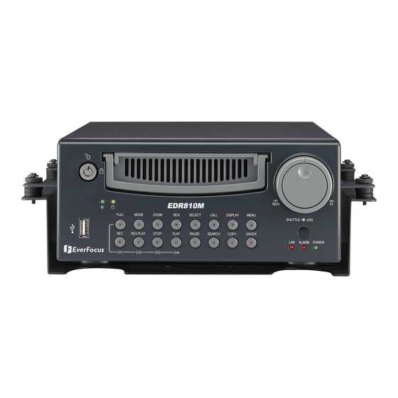
Page 13: Front Panel Keypads
Keys: Channel Key: Press FULL+Channel Key (CH1~CH8) to display video image in the full screen format; the picture of the corresponding channel will fill the whole screen. CH1 / REC: Press this key to start instant recording. CH2 / REV. PLAY: Reverse Play Back. CH3 / STOP: Press this key to stop recording and playing back. - Page 14 FULL: Press this key and channel Key at the same time to switch to full screen in both live mode and play back mode. Press “MODE” to exit full screen. MODE: Switch PIP (Live only), 4, 7 and 9 displays in Live and Playback modes. ZOOM: In full screen mode, 2x electronic zoom.
- Page 15 MENU: Press this key to enter or exit MAIN SETUP MENU or to exit from any submenu. HDD Lock: Keeps HDD in place and turns on HDD power. Hard Disk Tray: Hard Disk holder for HDD. Shuttle and Jog Dial Shuttle: In the Playback mode, turn the Shuttle dial to fast forward/rewind the video.
-
Page 16: Back Panel Connections
Back panel of 810H Back panel of 810M Back panel of 410H Back panel of 410M... - Page 17 POWER Main Power plug: Connect the DC 12~ 24V power source to adapter for AC 100~ 240V. Audio IN: Audio input for recording, and it can be set to “YES” or “NO” in the RECORD SETUP MENU. Audio OUT: Connect an audio output to a monitor or other device. MONITOR MAIN MONITOR: This connector is used for the main monitor display, a number of different display modes may be selected for viewing.
- Page 18 LAN Connector: RJ-45 network connection. RS232 RS232 connector: D-Sub 9-pin connector to RS232 ports for testing purpose ONLY. RS485 RS485 connector: RJ 45 Connector to cascade/control multi Digital Video Recorders. Remote Remote Control: Remote control port allows for an extension wire with an IR receiver instead of the IR receiver on the front panel.
-
Page 19: Monitor Display
The status information of the cameras or machine will show up, and be located at different places on the screen. 1. Channel tag 2. Event sign 3. Select sign 4. Play status bar 5. Record status bar For mobile model only: 6. - Page 20 Channel tag: A channel tag indicates the channel name of the screen. Event sign: Event signals which are small icons with a capital letter and red background show the events on each screen. There are a total of 6 different signals: Alarm event.
- Page 21 Play Date Play Status Play Time 1. Play date The date on which the video was recorded. 2. Play status “PAUSE”, when the video playback is paused. “P## >” means normal play speed on the displayed disk number; “P## <“ means normal reverse play speed on the displayed disk number; “##%”...
- Page 22 Event The current/last event that occurred. Current time The current time, which can be set in the TIME/DATE SETUP MENU. HDD/FAN status “No Disk”: only shows when no disk is installed or detected. “No Fan”: only shows when internal fan stops working. “HDD OT”: only shows if hard drive is over temperature.
-
Page 23: Installation
Chapter 2. Installation The installations described below should be done by qualified service personnel or system installers. I) PACKING Please check accessories in the packing before the installation. II) SYSTEM FLOORPLAN Please refer to the following diagrams for the system connections. Note: Monitor and Camera must be purchased separately. -
Page 24: Basic Wiring Instructions
Please refer to diagram 2.1 to assist you with this portion of the installation. 1. Power Connect the power source or adapter into the power socket. 2. Cameras Connect each cameras video output to the video inputs on the digital video recorder. Note: At least one camera must be connected before the system is running for the auto detection of video standard to take effect. - Page 25 8. Call Monitors Connect the call monitor output connectors to a call monitor. The call monitor display selected live cameras in full screen format. Note: The call monitor will only display one full screen camera at a time.
-
Page 26: Hard Disk Drive Installation
The first step in installing the hard drive is to insert the hard drive sleeve into the machine. The hard disk drive default setting is initially set to master. The second step is to insert the key provided and turn the tray key to the lock position. -
Page 27: Quick Installation Guide For Edr810M & Edr410M Only
& & The EDR810M & EDR410M are the full-featured digital video recorders designed specifically for use in mobile applications. Please refer to the following Quick Installation Guide for installing EDR810M or EDR410M into mobile applications such as buses, cars and police cruisers. The DVR can be mounted horizontally (suspend or support mounted). - Page 28 Unpack Everything Make sure you have everything you need before you begin the installation. Equipment Required The following tools may help you to complete the installation: Drill Screwdrivers Wire cutters Choosing the Location Choose a location for installation that: Provides convenient access for installing or removing the hard drive Allows air to flow around the fan vents.
- Page 29 Possible Installation Locations Inside the Automobile Vehicle: Truck Glove box (inside or underneath) Drive seat (between seat and wall) or Passenger seat (underneath) (Users are suggested to use “support” for mounting option) Show the wiring on the wiring harness that connects to the electrical system. (24 V) (5 A)
- Page 30 Possible Installation Locations Inside the Automobile Vehicle: TOYOTA CAMRY Glove box (inside or underneath) Trunk (Users are suggested to use “suspend” for mounting option) Passenger seat (underneath) Drive seat (between seat and wall) Show the wiring on the wiring harness that connects to the electrical system.
- Page 31 Installing the Camera(s) and Monitor The DVR is typically connected to one camera installed inside the car. Other camera(s) can also be installed in different locations (for example, use the waterproof camera to the outside of vehicle). For installation procedure, please refer to the guide that came with the camera(s) you purchased.
-
Page 32: Dvr Menu Setup
Chapter 3. DVR Menu Setup Assuming you have completed the first two chapters of this manual, you are now ready to begin setting up the digital video recorder. The following chapter will walk you through the detailed DVR Menu step by step and how to set the DVR for your specific application. -
Page 33: Time /Date Setup Menu
Diagram 3.2 Diagram 3.2 is a screenshot of the TIME/DATE SETUP MENU. This menu is used to set up the correct time and date for your region of the world. You are able to setup daylight savings as well as synch it with an internet based time server. - Page 34 5. DAYLIGHT SAVING: This field represents the daylight savings on the DVR. To change this, simply use the Jog Dial on the DVR. Select “ON” or “OFF” to enable or disable daylight saving time function. This feature must be disabled in order to make any changes to the start and end times.
- Page 35 8. TIME SYNCHRONIZE: Select “ON” or “OFF” to enable or disable time synchronize which will automatically update the DVR’s time when connected to a network. To change this, simply use the Jog Dial on the DVR. TIME SERVER: You can set the time server address that the DVR connects to for time synchronize.
- Page 36 Alaska Standard Time subtract 9 hours from GMT Hawaii-Aleutian Daylight Time subtract 9 hours from GMT Hawaii-Aleutian Standard Time subtract 10 hours from GMT 11. TIME UPDATE BY: Once you enable the TIME SYNCHRONIZE, you can select the synchronization frequency by: WEEK MONTH...
-
Page 37: Camera Setup Menu
Diagram 3.4 Diagram 3.4 is a screen shot of the CAMERA SETUP MENU. This menu will walk you through setting up the Camera Recording Speeds, Camera Titles, PTZ ID, covert modes, and recording quality. In the CAMERA SETUP MENU the following fields are defined as: 1. - Page 38 4. SEQ (MAIN/CALL): Set the number of seconds a camera is displayed in sequence. The first number is for sequence on the Main Monitor, the second number is for sequence on Call Monitor. 5. REC QUALITY: Select an image quality for recording. There are six different qualities available. A higher image quality uses more HDD space.
- Page 39 6. REC SPEED & ACTION: TP: Scheduled recording time 1~8 which can be set in the SCHEDULE SETUP MENU. “N” is the normal recording time, which is activated by pressing the Record button. If you have set a Time Period in Schedule Setup Menu, then there will be a star sign (*) beside that TP in Camera Setup Menu.
- Page 40 7. SUMMARY: Diagram 3.5 Dial Jog to change items in the SUMMARY table. All cameras’ statuses are shown in the SUMMARY table. The table is for checking camera overall statuses only, not for changing them. Note: The SUMMARY table also exists in ALARM, MOTION and VLOSS SETUP MENU. All of these SUMMARY tables are also for checking particular overall statuses, not for changing them.
-
Page 41: Record Setup Menu
Diagram 3.6 Diagram 3.6 is a screen shot of the RECORD SETUP MENU. This menu is for setting up the options for recording. In the RECORD SETUP MENU the following fields are defined as follows: 1. RECORD AUDIO: YES: Audio will be recorded when machine is recording and a microphone is connected. NO: Audio will not be recorded when machine is recording. - Page 42 4. WATER MARK: ON: Recording is overlaid by a visible watermark (“W”). OFF: No watermark. RESOLUTION: The resolutions for NTSC are 720x480, 720x240 and 360x240; the default value is 720x240. The resolutions for PAL are 720x576, 720x288 and 360x288; the default value is 720x288.
-
Page 43: Alarm Setup Menu
Diagram 3.7 Diagram 3.7 is a screen shot of the ALARM SETUP MENU. An alarm is defined as an electrical, electronic, or mechanical device that sends an alert by means of a signal. In this case the signal triggers the recorder to start recording the alarmed event. This menu contains all the alarm operations and options needed to successfully set up an alarm recording. - Page 44 3. LOG: ON: Select ON if you wish to record Alarm Events in the Log. OFF: Select OFF if you do not wish to record Alarm Events in the Log. 4. ACTIVE CAMERA: This field is to activate camera you want to have the alarm enabled too. For example if you had an external motion detector on camera one you would set this option to camera one.
- Page 45 10. ALARM NETWORK: YES: Enable alarm network. NO: Disable alarm network. 11. MAIN MON: Display on a main monitor when an alarm occurs. NO CHANGE: No change on the display in the main monitor when an alarm occurs. FULLSCREEN: A full screen of the active camera will display when an alarm occurs. 12.
-
Page 46: Motion Setup Menu
Diagram 3.8 Diagram 3.8 is a screen shot of the MOTION SETUP MENU. We define motion as a change of pixilation in the field of view, which is detected by the digital video recorder, and triggering the recorder to start recording. Motion is also considered an event. This menu is for setting up the digital recorder for motion recording on a per camera basis. - Page 47 4. DURATION: The amount of time a motion event will record - from 1 sec to 99 seconds. The default value is 5 seconds. To change this, simply use the Jog Dial on the DVR. 5. ALARM OUTPUT: This will transmit a signal to another device. The setting of alarms are NONE = not activated, 1 = output signal 1 transmitted.
- Page 48 To edit a MOTION AREA, enter a desired channel and press SELECT. Motion must be set to “Enable” in order to edit the motion detection area. In the motion edit mode: The default motion area of each camera is entire screen which displays in light green.
-
Page 49: Videoloss Setup Menu
Diagram 3.9 Diagram 3.9 is a screen shot of the VIDEOLOSS SETUP MENU. VIDEOLOSS event is caused when no video signal input is detected on a channel. Usually it happens when the camera loses power or the camera fails. In the VIDEOLOSS SETUP MENU the following fields are defined as follows: 1. - Page 50 5. ALARM EMAIL: Select “YES” for sending an email when video loss occurs. The email address can be set in the NETWORK SETUP MENU. 6. BUZZER: Audible alarm buzzer. ENABLE: To enable a video loss buzzer. DISABLE: To disable a video loss buzzer. 7.
-
Page 51: Network Setup Menu
Diagram 3.10 Diagram 3.10 is a screen shot of the NETWORK SETUP MENU. This menu is for setting up the configurations for networking to the DVR. There are 6 subentries that are CONFIG, ALARM, EMAIL, PASSWORD, PPPoE and DDNS in the NETWORK SETUP MENU. Mobile units will also have the WIRELESS and GPS features available. - Page 52 IP Address This field shows the current IP Address for the DVR. A Fixed IP address does not change and must be set manually. To change this, simply use the Jog Dial on the DVR. When DHCP is selected, DHCP server will assign this value automatically. Note: The addresses in the machine are for our own testing you should apply your own addresses to comply with your network.
- Page 53 Note: If you wish to have multiple users log into the DVR, please open a range of ports on your router. For example if you want to allow 4 clients to login through the default port 37260, you should open the port range 37260-37263 on your router. 10.
-
Page 54: Alarm Network
3.7.2 ALARM NETWORK DVR can send out Alarm message to an Alarm Server. This function is reserved to work with our Control Management System – PowerCon 4. In the ALARM of the NETWORK SETUP MENU, we define: Diagram 3.11 1. PROTOCOL: Select which communication protocol with Alarm servers or Alarm receiving clients. -
Page 55: Email
3.7.3 EMAIL In the EMAIL of the NETWORK SETUP MENU, we define: Diagram 3.12 1. SMTP SERVER Assign the SMTP (e-mail) server’s name. Note: For more reliable email service, use the server’s IP address. 2. PORT NUMBER Assign the port number for SMTP server. The default port is 25. 3. -
Page 56: Password
7. SENDER EMAIL ADDR Input sender’s e-mail address, so that receiver can recognize the sender when an event message is sent out. 3.7.4 PASSWORD In the PASSWORD of the NETWORK SETUP MENU, we define: Diagram 3.13 Name/Password/Level: This category is to set up the users that will log into the network. Please remember that this portion of the Network setting menu is set up in column format. -
Page 57: Wireless
3.7.5 WIRELESS In the WIRELESS of the NETWORK SETUP MENU, we define: Diagram 3.14 1. DHCP: Enable or disable the Dynamic Host Communication Protocol. YES: Enable DHCP service. NO: Disable DHCP service. 2. IP ADDRESS: Assign an IP address for this unit, for example: 192.168.010.200 When DHCP is YES, the DHCP server will assign this value automatically. - Page 58 Shared: need shared key. WEP: uses encrypted data transmission. Wireless networks broadcast messages using radio and are thus more susceptible to eavesdropping than wired networks. WPAPSK: Each user must enter a passphrase to access the network. TKIP: Randomizes the key used for each packet. The key is created by mixing together a base key, the MAC address of the transmitting station, and the serial number for the packet.
-
Page 59: Pppoe
3.7.6 PPPoE In the PPPoE of the NETWORK SETUP MENU, we define: Diagram 3.15 USER: User name that is provided by ISP for PPPoE connection PASSWD: Password that is provided by ISP for PPPoE connection PRIMARY DNS: IP address of DNS server that is provided by ISP. SECONDARY DNS: If your ISP provides a secondary DNS address, please set it here. -
Page 60: Ddns
3.7.7 DDNS In DDNS of the NETWORK SETUP MENU, we define: Diagram 3.16 1. SERVER: DDNS provider. 2. USER: User name of the account. 3. PASSWD: Password of the account. 4. RECORD ID: Record ID. 5. FQDN: The domain name of this account. For example: A user had applied for a DDNS account from Http://www.dyndns.org. - Page 61 EVERFOCUS DDNS If you are using software 1.6.2 or higher, you can use the EverFocus DDNS server. 1. First, go to the website http://everfocusddns.com and check for an available name 2. In the DDNS Menu, choose “EverFocus DDNS” for Server 3.
-
Page 62: Gps
3.7.8 GPS In GPS of the NETWORK SETUP MENU, we define: Diagram 3.17 1. AUTOMATIC GPS 2. TRANSMISSION: YES: select YES to enable transmission NO: select NO to disable transmission 3. UNIQUE ID: Input GPS Unique ID. 4. GPS TRANSMISSION CYCLE TIME IN SECONDS: Enter GPS transmission cycle time in seconds. -
Page 63: Schedule Setup Menu
Diagram 3.17 Diagram 3.17 is a screen shot of the SCHEDULE SETUP MENU. In this menu you can set a unique timer any day of the week to start recording from a specified start time to an end time. You will notice TP (time period) 1~8, which is also seen in the Camera Menu. - Page 64 3. END: This field is used to set the time you wish to stop the timer recording. To change this, simply use the Jog Dial on the DVR. Hour: 0 ~ 23 in 24 hour time format; 1~12 in 12 hour time format. Minutes: 00 ~ 59 Note: To record all day long, use 12:00am~12:00 am for 12-hour-format or 00:00~00:00 for 24-hour-format.
-
Page 65: Disk Setup Menu
Diagram 3.18 Diagram 3.18 is a screen shot of the DISK SETUP MENU. This menu is for viewing Disk information and formatting the disks. For every configuration change or initial setup we recommend formatting the Hard Disk. In the DISK SETUP MENU the following fields are defined as follows: 1. - Page 66 THERMOMETRIC SCALE: Select CELSIUS or FAHRENHEIT for thermometric scale of the disk. NO/SIZE/C or F/Start/End Time: Show the number of drives, the size of each drive, the temperature, and the range of days and times stored on the hard drive.
-
Page 67: Control Setup Menu
Diagram 3.19 Diagram 3.19 is a screen shot of the Control Setting Menu. This menu is for setting up a connection from the digital recorder to a computer to transfer instructions or information using a keyboard or software. In the Control Setting Menu the following fields are defined as follows: RS232: RS232 Baud Rate: This field is to set the speed at which is used to transmit instruction or information through RS232 on the DVR. - Page 68 RS232/RS485 connection. The ID code for the DVR can be set from 001-255. The default is set to 001. To change this, simply use the Jog Dial on the DVR. 10. PTZ PROTOCOL: Select PTZ protocol from EVERFOCUS, PELCO-D, PELCO-P and ED2200/2250.
-
Page 69: Warning Setup Menu
Diagram 3.20 Diagram 3.20 is a screen shot of the Warning Setup Menu. This menu is to set the warning system settings. If any critical errors arise, this portion of the menu is used for handling them. In the Warning Setup Menu the following fields are defined as: 3.11.1 FAN FAULT In FAN FAULT, we define:... -
Page 70: Hdd Temp
4. NETWORK ALARM: YES: To enable network alarm. NO: To disable network alarm. 5. SEND EMAIL: YES: Send an email when the fan does not work. NO: Do not send an email when the fan does not work. The email address can be set in the NETWORK SETUP MENU. 3.11.2 HDD TEMP In HDD TEMP, we define: Diagram 3.21... - Page 71 2. ALARM OUTPUT: This will transmit a signal to another device. The setting of alarms are NONE = not activated, 1 = output signal 1 transmitted. To change this, simply use the Jog Dial on the DVR. 3. ALARM DURATION: Permanent, this setting cannot be changed. 4.
-
Page 72: No Hdd
3.11.3 NO HDD In NO HDD, we define: Diagram 3.22 1. BUZZER: NO HDD buzzer. ENABLE: To enable a buzzer when no HDD has been found. DISABLE: To disable NO HDD buzzer. 2. ALARM OUTPUT: This will transmit a signal to another device. The setting of alarms are NONE = not activated, 1 = output signal 1 transmitted. -
Page 73: Hdd Full
5. SEND EMAIL: YES: Send an email when no HDD has been found. NO: Will not send an email when no HDD has been found. The email address can be set in the NETWORK SETUP MENU. 3.11.4 HDD FULL In HDD FULL, we define: Diagram 3.23 1. - Page 74 4. NETWORK ALARM: YES: To enable network alarm. NO: To disable network alarm. 5. SEND EMAIL: YES: Send an email when HDD is full. NO: Will not send an email when HDD is full. The email address can be set in the NETWORK SETUP MENU.
-
Page 75: System Setup Menu
Diagram 3.24 Diagram 3.24 is a screen shot of the SYSTEM SETUP MENU. This menu is for setting up any additional options and restoring defaults to the digital recorder. In the SYSTEM SETUP MENU the following fields are defined as follows: 1. - Page 76 4. UPDATE SYSTEM SOFTWARE: Turn the jog to enter the selection window. YES: Select YES to update system software from USB and press SELECT to start. NO: Select NO and press SELECT to cancel update. Note: - System will ask you to stop recording before you can update the system. -USB device must be inserted properly before updating system software.
- Page 77 PASSWORD and RIGHTS: The login passwords in this menu are used to operate and set up the machine locally, not from the remote TCP/IP connection. The different passwords indicate the different level of users, and no login name is necessary. The digit will appear instead of a “*” sign when the cursor is moved on it.
-
Page 78: Recording Overview
Chapter 4. Recording Overview Before continuing with the Recording Overview please be sure to have reviewed DVR Menu Setup (Chapter 3), specifically the Camera & Schedule Menus. You are now ready to begin setting up the machine for recording. This chapter will show you how to setup the recorder for three basic types of recording: Instant recording, scheduled recording, and event recording. -
Page 79: Schedule Recording Setup
Note: 1. In order to start or stop Instant Recording, you must exit completely from all menus. 2. If STOP is pressed while machine is recording and playing video, the playing function will be disabled first. If STOP is pressed twice the DVR will come out of record mode completely. -
Page 80: Event Recording Setup
We will define two event recording types ALARM and MOTION. After the event recording is enabled, the DVR will start an event recording when an event occurs. For instance when motion activity is detected by the DVR it will begin recording at the specific IPS set under event column. Or when an alarm is detected by the DVR it will begin recording at the specific IPS set under event column. - Page 81 2. When the event is set, enter the CAMERA SETUP MENU to set the event recording speed (IPS) of the camera for TP N (Instant Recording) or TP 1~8 (Schedule Recording). Diagram 4.3 Once the event and record and speed are set, you need to activate Instant Recording or set a time period in the SCHEDULE SETUP MENU.
- Page 82 Note: 1. If you only want to record event (motion or alarm) activity ONLY, set the normal record speed as 0 IPS in the CAMERA SETUP MENU. 2. If the recording speed is changed while the machine is recording, the new recording speed will not take effect until recording is completely stopped and then reactivated.
-
Page 83: Playback Overview
Chapter 5. Playback Overview Before continuing please be sure to have reviewed DVR Menu Setup (Chapter 3). This chapter will show you how to setup the recorder for playback. (1) Playback Press the PLAY key to start playing back the stored image/audio. The video start time depends on the quick play setting in the SYSTEM SETUP PLAY MENU. - Page 84 (3) Fast Forward/Reverse Playback While in playback, turn the Shuttle dial clockwise to begin fast forward playback. PLAY Turn the Shuttle dial counterclockwise to begin fast reverse playback. The speed will be shown on the status bar of the bottom screen. The available speeds are 2, 4, 6, 8, 16, 32, and 600.
- Page 85 (5) Image advance Forward/Reverse Press PAUSE key to freeze the picture. PAUSE Turn the Jog dial clockwise to advance the still video image by image. Turn the Jog dial counterclockwise to rewind the still video image by image. The field feed speed will increase if the Jog dial is turned quickly.
-
Page 86: Search Playback
Press the SEARCH key to enter the SEARCH MENU. In the SEARCH MENU, SEARCH Press the ENTER key to go to the next subentry. Press the DISPLAY key to go to the previous subentry. Dial the Jog clockwise or counterclockwise to change subentry values. Press MENU key to exit. - Page 87 (2) EVENT Search Playback To search by “EVENT”, select “BY EVENT” for Method. Set the Start and End Date/Time limits for the events to be searched. Only events within the selected Date and Time will be displayed 7 filters (ALARM, MOTION, VLOSS, A/M, A/V, M/V and A/M/V) can be selected. The indications of events show as below.
- Page 88 The event types and number show on the second column of the search list. An: an Alarm event, n = input number Dn: HDD overheated, overheat temperature is based on HDD temperature set in Warning Setup Menu. n = disk number Fn: Fan fail, n = 1~3 fan number.
-
Page 89: Copying Video
Chapter 6. Copying Video Before continuing please be sure to have reviewed the preceding chapters. You are now ready to copy an image or video from the DVR. This chapter will show you how to copy a still image or movie from the recorder. - Page 90 Diagram 6.1 In the COPY MENU, we define: 1. COPY: Select Image for copying images (video) to movie file. Select Viewer for copying EDR Viewer player. 2. DISK NO: Disk number. It is fixed as “01” in this series. 3. CAMERA NO: Camera channel number. You can select the video of camera you would like to copy.
-
Page 91: Iewing Aopied Ile
a. If a file size exceeds 2GB, the DVR will automatically split it into smaller video clips that will be copied individually. The current segment and completion percentage are displayed at the bottom of the screen. b. While in playback, pressing COPY button will set a start and end time in the Copy Menu for span of 1 minute. -
Page 92: Call Overview
Chapter 7. Call Overview This chapter will give you basic details on how to setup the CALL MENU on the DVR. Press the CALL key and the CALL MENU will pop up as below. Diagram 7.1 In CALL MENU, you can change the following settings for the call monitor: 1. -
Page 93: Screen Display Setting & Mode
Chapter 8. Screen Display Setting & Mode In a full screen display, press SELECT key to pop up the display adjustment window as below: Diagram 8.1 In the screen display setting menu, we define: 1. CAMERA: The current camera. 2. BRIGHTNESS: The bright percentage of the current camera; from 0% to 100%. 3. -
Page 94: Mode Button
When turning SHARPNESS OFF, the image becomes slightly blurred in an indoor environment. However, this option is suitable for outdoor use. If image flickers under a bright, outdoor environment, then the image can become mild by turning SHARPNESS OFF. The selected item will show in red color bar. Use Jog to increase or decrease the value. Press ENTER to confirm the setting value and move to next item. -
Page 95: Upgrade Firmware
This chapter will give you basic instructions on how to upgrade the DVR’s software. This will be a helpful in completing the upgrading process. Go to http://www.everfocus.com/support_bulletins.asp and find the DVR you have. Click on the link to save the upgrade file to your computer. -
Page 96: Networking Overview
Chapter 10. Networking Overview This chapter will try to give you a detailed instruction on how to network the DVR. Before we begin the process of networking your digital recorder we should have a working knowledge of what a network is and how it works. This will be a helpful in completing the networking process. TCP/IP is the suite of protocols used by the Internet and most LANs (Local Area Networks) throughout the world. -
Page 97: Gateway Address
Sometimes, though, port numbers are made visible to the casual user. For example, some Web sites a person visits on the Internet use a URL like the following: http://www.everfocus.com:8100/ In this example, the number 8100 refers to the port number used by the Web browser to connect to the Web server. - Page 98 That way, you can host a website, email server, or other type of server connection. Everfocus suggest using a static IP address. If your Internet provider does not offer a static IP address you have the option to use a dynamic IP address. This will be explained in more detail later on in the chapter.
-
Page 99: What Type Of Network Connection Do You Have
Everfocus DVR’s can operate using three distinct types of networking connections. 1. Simple One to One Connection: A simple one to one connection is the most simple network connection. Basically it is a connection between a Computer and Another Computer or in this case a DVR using a cross-over cable. -
Page 100: Simple One To One Connection
Now Log into the Everfocus DVR menu and using the jog dial from the previous chapter go to the Network Setting Menu. (Please see Network Setting Menu for more instructions) Assign an IP address of 192.168.001.003 to the DVR, a Subnet mask of 255.255.255.000,... - Page 101 The next step is to get the computer onto the same network to do this you will need administrator access to your windows machine. To assign a static IP address in windows 2000/XP.
- Page 105 Once you have reached this point click ok and restart both the computer and the digital recorder. To access the DVR from the computer simply open Internet Explorer and in the address bar type: http://192.168.1.3...
-
Page 106: Direct High Speed Modem Connection
Hi-speed modem Internet Cat 5 Straight Through Cable Straight Through Ethernet Cable Pin outs: The Diagram below shows the pin configurations for a straight cable. Diagram 10.2 Connection Procedure: The First step is to purchase or make a straight through cable. We recommend purchasing one if you have never made a straight through cable. - Page 107 Now Log into the EverFocus DVR menu and using the jog dial from the previous chapter go to the Network Setting Menu. Assign the Static IP address which you obtained from the internet service provider to the DVR, the Subnet mask from the internet service provider to the DVR, and the default gateway of the internet service provider.
-
Page 108: Router Or Lan Connection
Hi-speed modem Internet Cat 5 Router Straight Through Cable Straight Through Ethernet Cable Pin outs: The Diagram below shows the pin configurations for a straight cable. Diagram 10.3... - Page 109 Once you have a straight through cable plug one end into the LAN port on the back of the recorder and the other into the router. Now Log into the EverFocus DVR menu and using the jog dial from the previous chapter go to the Network Setting Menu.
- Page 110 Use the prior step to assign an IP address. For example, if you got the IP address from the computer of 192.168.002.101. Assign the DVR’s IP address as 192.168.002.050. Now Copy the subnet mask and default gateway information you got from the prior step off the computer to the DVR.
-
Page 111: Linksys Port Forwarding
Chapter 11. Linksys Port Forwarding This chapter will cover a few simple configurations for the Linksys router. Please understand we do not support this product and will not give tech support on it. If you need technical support on this router you must call Linksys. This chapter is to offer some help to the installer and end user, nothing more. - Page 112 Sample Screen The Applications and Gaming Tab allows you to set up public services on your network, such as web servers, ftp servers, e-mail servers, or other specialized Internet applications. (Specialized Internet applications are any applications that use Internet access to perform functions such as videoconferencing or online gaming.
-
Page 113: Dynamic Dns
application. Enable - Click the Enable checkbox to enable port forwarding for the relevant application. Change these settings as described here and click the Save Settings button to apply your changes or Cancel Changes to cancel your changes. Example: 80 to 80 Both 192.168.1.50 Enable 1600 to 1600... - Page 114 Internet IP Address - This is the Router’s current IP Address as seen on the Internet. Status - This displays the status of the DDNS connection. Change these settings as described here and click the Save Settings button to apply your changes or Cancel Changes to cancel your changes.
-
Page 115: D-Link Port Forwarding
Chapter 12. D-Link Port Forwarding This chapter will cover a few simple configurations for the D-Link router. Please understand we do not support this product and will not give tech support on it. If you need technical support on this router you must call D-Link. - Page 116 The next step is to open ports within your router. Go to Virtual Server in the router. Example1: Protocol Type - The protocol used for the virtual service. Public Port - The port number on the WAN (Wide Area Network) side that will be used to access the virtual service.
- Page 117 Name - Enter the name referencing the virtual service Private IP - The server computer in the LAN (Local Area Network) that will be providing the virtual services. If you have a Web server that you wanted Internet users to access at all times, you would need to enable it.
- Page 118 Once you have enabled it enter the server address of DynDNS.org: members.dyndns.org Then enter the hostname you created with DynDNS.org Example: Everfocus.homeip.net Then enter the username and password you use to log into DynDNS.org...
-
Page 119: Everfocus Ddns Setup
Chapter 13. EverFocus DDNS Setup Note: You MUST have firmware version 1.6.2 or higher in order to use the EverFocus DDNS server. Set up the Network Menu according to the instructions detailed in the Networking chapter. Go to the website http://everfocusddns.com... - Page 120 Press the Select button to synchronize the DVR with the DDNS server. You should see the word “Success” at the bottom of the screen. If you see “Could Not Find Server” instead, double check your network settings until you get “Success”. You should now be able to connect by typing in the host name you created.
-
Page 121: Viewing Through Internet Explorer
Chapter 14. Viewing through Internet Explorer To access the DVR from a computer simply open Internet Explorer and in the address bar type: http:// (LAN address or IP address of your internet service provider) After a few seconds, you should see a screen like the one above. If you do not see a yellow bar like the one the arrow is pointing at, your security settings may be too high. -
Page 122: Enabling Activex Controls
User must enter a user name and password to access the recorder. User Name and Password can be found and changed in the Network Menu of the DVR. The Default user name is admin and password is 11111111. Click Login to view the cameras. - Page 123 Click the Security tab at the top, then choose Custom Level near the bottom. In the Security Settings window, scroll to “ActiveX controls and plug-ins”. Set the controls as follows: “Enable”: Allow previously unused ActiveX controls to run without prompt (Internet Explorer 7 only) Allow scriptlets (IE7 only) Automatic prompting for ActiveX controls...
- Page 124 Click the Refresh button to reload the page and install the MP4DVR file when prompted to do so. Type in the username and password and click Login to view the cameras. Main Screen: 13 14 The above diagram is the main screen display. The icons in the right corner of the screen are mainly for control and configuration;...
- Page 125 The followings are a brief description for each of the icons. REV. PLAY: Reverse Video Playback. STOP: Press this key to stop Playback and return to Live mode. PLAY: Normal Video Playback. STEP BACKWARD: Move one frame back while paused. PAUSE: To pause the Video Playback display.
- Page 126 20. Event Description: By clicking on the sign, an event description list will show up as follow: 21. Record: Press the button to remotely activate the DVR’s record function. Press again to stop recording. 22. Audio: This function allows you to transmit audio from DVR to your PC’s remote site. Select audio source 1/2/3/4, or “OFF”...
-
Page 127: Search
14.1.1 Search by Time There are 3 ways to do search by time. First press 1. Press the M button to change the month to be searched, D for day, h for hour, m for minute and s for second. The buttons on the left-hand side are to decrease the value, whereas those on the right-hand side are to increase the value. -
Page 128: Search By Event
14.1.2 Search by EVENT 1. Select Event Type from Alarm, Motion and Vloss. Note: At least one event type must stay checked. 2. Select the Disk No. from which you would like to search events. 3. Press Update button to refresh the event list. 4. -
Page 129: Ptz Control
1. Select the PTZ camera you wish to control from drop-down menu. 2. Select Action Mode you want to use. There are 4 options available: Continuous, Step x10, Step x5 and Step x1. 3. Use Direction Arrows (up, down, left, right) to move/adjust the focus to your desired direction and angle. -
Page 130: Remote Archive
To Archive files: 1. Select Disk No.: The hard drive you want to archive from 2. Disk Storage Time: Start Time/End Time indicates the start and end time of the selected disk 3. Camera: Select the camera that you wish to archive from. 4. - Page 131 1) Press on the M button to change the month to be searched, D for day, h for hour, m for minute and s for second. The buttons on the left side are to decrease the value, whereas those on the right side are to increase the value. 2) Move the slide bar between the buttons to change Month, Day, Hour, Minute, and Second to be searched.
- Page 132 In order to play the archived EDR MPEG4 Files (.arv), you will need to download viewer: I. Press Download DVRViewer button. II. Select “Run” or “Save” the file.
- Page 133 III. Open the DVRViewer.exe for loading the archived EDR MPEG Files (.arv) Detailed explanation of DVRViewer is as follows: 1. Load File: load an archived EDR MPEG File (.arv). 2. Stop: stop playback. 3. Play: play video. 4. <<Step: move the paused image one step backward. 5.
- Page 134 Note: (1)The recording frame rate will be automatically calculated. It is suggested to use the calculated Recording Frame Rate, although it is possible to change this value. (2) If you wish to save the audio recorded, please select Audio ON, so that the audio can be transferred to AVI file.
-
Page 135: Remote Configuration
Click on the “CONFIG” tab to open a page where you can remotely change the DVR’s settings. Click on each option to go to the settings for that page. When you finish making changes on a screen, press Apply to save the settings. Press Reset to display the DVR’s current menu settings. - Page 136 DATE/TIME setup menu Set Date/Time Manually 1. Click on the calendar button to set Date/Time manually. A calendar will show up as shown below. 2. Click “<<” to decrease Year value, “>>” to increase Year value. 3. Click “<” to decrease Month value, “>” to increase Month value. 4.
- Page 137 CAMERA setup menu RECORD setup menu ALARM setup menu...
- Page 138 MOTION setup menu Set Motion Grid 1. Non-green squares are disabled for motion; green squares are enabled. 2. Click and hold the mouse to begin selecting squares in the motion grid. 3. Drag the mouse to highlight the desired area. 4.
- Page 139 NETWORK 1 setup menu The Network Configuration Settings can not be changed remotely. These must be changed in the DVR’s Network Menu. NETWORK 2 setup menu After saving changes to the account, password, or level, the changes will take effect the next time you log in to the network viewer.
- Page 140 SCHEDULE setup menu CONTROL setup menu...
- Page 141 WARNING setup menu SYSTEM setup menu All recording should be stopped before making any changes on this menu. Update Firmware 1. After clicking Apply, an “Open File” window appears. 2. Find the folder where the firmware upgrade is saved and choose Open. 3.
-
Page 142: Interface Specifications
Chapter 15. Interface Specifications RS485 This Digital Video Recorder may be controlled by a computer or control keyboard (EKB500) via the RS485 interface. Pin definition of RS-485 connector on DVR back panel is shown in the following picture. 1 2 3 4 5 6 7 8 Pin 3: RS-485 + Pin 6: RS-485 - There are 6 different speeds that can be used to transmit instruction or information through the... -
Page 143: Remote Control Protocol
A computer can be used to control the DVR by sending the packet as follows. ========================================================= 485/232 Control Code Protocol ========================================================= 1-1. Sample control code packets Example1: A packet that send "REC" key to EDR(ID=5) 0x85 (length) 0x00 (Receiver ID high byte) 0x05 (Receiver ID low byte) 0x4B (OPcode = key) 0x08 (DATA1 = "Rec"... - Page 144 0000001 0000000 ID = 128 0000001 0000001 ID = 129 0000001 1111111 ID = 255 0000010 0000000 ID = 256 ..0000011 1111111 ID = 511 ..16382 1111111 1111110 ID = 16382 ---------------------------------------------------------- 2). Broadcast ID ---------------------------------------------------------- Decimal 14bit binary value Hbyte Lbyte Receiver ID ------- ------------------- ------ ----- ----------- 16383 1111111 1111111 7f All EDR connect to RS485/RS232...
- Page 145 0x23 CH8 0x24 (reserve) 0x25 (reserve) 0x26 (reserve) 0x27 (reserve) 0x28 (reserve) 0x29 (reserve) 0x2a (reserve) 0x2b (reserve) 0x2c SELECT 0x2d CALL 0x2e ENTER 0x2f (reserve) 0x30 (reserve) 0x31 (reserve) 0x32 (reserve) 0x33 (reserve) 0x34 (reserve) ------------------------------- 2-5. Checksum Byte Checksum is computed as the sum of all previous bytes (including the length byte), then mask with 0x7f.
- Page 146 Appendix Appendix A: Remote Control...
- Page 147 Appendix Appendix B: Alarm Board Configuration Alarm I/O pin assignment The alarm connector, Figure 1, is used to provide one sensor alarm input for each camera input. For easy operation, an alarm extension board, Figure 2, is provided to connect to the alarm connector.
- Page 148 HOST PIN # NAME PIN # NAME ALM 1 ALM 1 ALM 2 ALM 2 ALM 3 ALM 3 ALM 4 ALM 4 ALM 5 ALM 5 ALM 6 ALM 6 ALM 7 ALM 8 ALM 7 ----- ALM 8 ----- ----- -----...
-
Page 149: Troubleshooting
Troubleshooting If you have difficulty operating your system, run through the following checklist to see if you can solve the problem. The DVR will not go into record mode? Make sure the HDD is locked in with the key. Also check to make sure the hard drive is set to Master. - Page 150 Chiba city 261-7118, Japan FAX: 631-436-5027 TEL : +81-43-212-8188 www.everfocus.com FAX : +81-43-297-0081 www.everfocus.com Ihr EverFocus Produkt wurde entwickelt Your EverFocus product is designed und hergestellt mit qualitativ and manufactured with high quality hochwertigen Materialien und materials and components which can Komponenten, die recycelt und wieder be recycled and reused.
Need help?
Do you have a question about the EDR810H and is the answer not in the manual?
Questions and answers