Table of Contents
Advertisement
Available languages
Available languages
Quick Links
Operator's
Manual
®
MITER SAW STAND WiTH
ROLLER EXTENSIONS
Model
No. 320.16491
WARNING:
To reduce the risk of injury,
the user must read and understand the
Operator's
Manual before using this product.
A_kWARNING:
To reduce the risk of injury,
the user must always read and follow
all
instructions
in the bench top tool operating
manual
before mounting
the tool to
this stand.
• WARRANTY
• SAFETY
• ASSEMBLY
• OPERATION
• MAINTENANCE
• ESPANOL
Sears Brands
Management
Corporation,
Hoffman
Estates,
IL 60179
U.S.A.
www,
ctaftsman,com
Advertisement
Table of Contents

Subscribe to Our Youtube Channel
Related Manuals for Craftsman 320.16491


Summary of Contents for Craftsman 320.16491
- Page 1 Operator's Manual ® MITER SAW STAND WiTH ROLLER EXTENSIONS Model No. 320.16491 WARNING: To reduce the risk of injury, • WARRANTY the user must read and understand the • SAFETY • ASSEMBLY Operator's Manual before using this product. • OPERATION A_kWARNING: To reduce the risk of injury, •...
-
Page 2: Table Of Contents
For warranty coverage details to obtain free replacement, visit the web site: www.craftsman.com This warranty is void if this product is ever used while providing commercial services or if rented to another person. This warranty gives you specific legal rights, and you may also have other rights which vary from state to state. -
Page 3: Safety Symbols
WARNING: Some dust created by power sanding, sawing, grinding, drilling and other construction activities contains chemicals known to the state of California to cause cancer, birth defects or other reproductive harm. Some examples of these chemicals are: • Lead from lead-based paints, Crystalline silica from bricks and cement... -
Page 4: Safety Instructions
WARNING: Be sure to read and understand all safety instructions in this Operator's Manual, including all safety alert symbols such as "DANGER," "WARNING," and "CAUTION" before using this tool. Failure to following all instructions listed below may result in electric shock, fire, and/or serious personal injury. - Page 5 SAVE THESE iNSTRUCTiONS Some of the following symbols may be used on this tool. Please study them and learn their meaning. Proper interpretation of these symbols will allow you to operate the tool better and more safely. SYMBOL NAME DESIGNATION/EXPLANATION Volts Voltage Amperes...
- Page 6 GENERAL POWER TOOL SAFETY WARNINGS A_, WARNING: Read and understand all instructions. Failure to follow instructions in this Operator's Manual may result in electric shock, fire, and/or serious personal injury. Save all warnings and instructions for future reference. READ AND SAVE THESE INSTRUCTIONS CAUTION: Do not modify the stand or use it for any application other than...
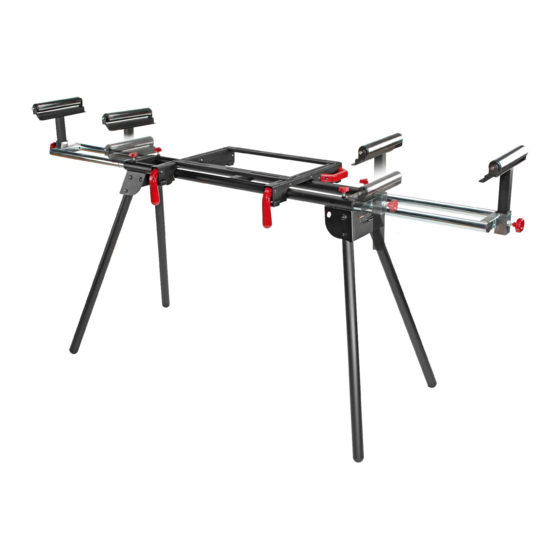
- Page 7 KNOW YOUR MITER SAW STAND (Fig. 1) Fig. 1 Extension Cross support Locking lever locking knob Roller assembly Roller-locking knob mounting brackets Frame assembly including legs PRODUCT SPECIFICATIONS Height 32-7/8 inches Extended width 80 in. Maximum Load Capacity 330 Ibs Weight 32.6 Ibs WARNING:...
-
Page 8: Table Of Contents
Do not discard the packing material until you have carefully inspected satisfactorily operated the stand. If any parts are damaged or missing, please return the stand to the place of purchase. PACKAGE CONTENTS AND HARDWARE Quantity item Description Frame assembly, including legs Quick-release... - Page 9 WARNING: Do not use this tool for scaffolding or as a ladder. Make sure to tighten all locking knobs and levers securely prior to use. Maximum capacity 330 Ibs. Power tools on the stand should not exceed a combined overall height of 60 inches from the floor.
- Page 10 Mounting Standard Miter Saws Fig. 5 To The Stand NOTICE: This allows for the miter saws on which the 4 mounting holes form a rectangular pattern (most miter saws). Mount your miter saw to the quick-release mounting brackets (B) using the miter saw mounting bolts (F), washers...
- Page 11 Mounting Non=Standard Fig. 9 Miter Saws NOTICE: This configuration allows for miter saws on which the 4 mounting holes holes form a trapezoid pattern (some saws) and the those on which the 3 mounting holes form atriangular pattern (few saws). Place the two support bars (C) on the mounting...
- Page 12 MOUNTING THE Fig. 13 ROLLER ASSEMBLIES Insert the roller assemblies (L) into Stop guide the mounting slots (Fig. 13). ° Adjust the height of the roller assemblies (L) as needed. Lock the roller assembly position by tightening locking knob (K) (Fig. 14). The roller assemblies can also use as a stationary...
- Page 13 ADJUSTING THE EXTENSION I Fig. 17 BARS (Fig. 17) Extend the extension bar to the required position to properly support the workpiece. Fully tighten the two extension- bar locking knobs (J). WARNING: When servicing, use only identical replacement parts. Use of any other parts may create a hazard or cause product damage.
- Page 14 MITER SAW STAND MODEL NO. 320.16491 The Model Number will be found on the Nameplate attached to the frame of the miter saw stand. Always mention the Model Number when ordering parts for this tool. To order parts, call 1-800-469-4663. Page 14 16491 ManuaLRevised_$2...
- Page 15 MITER SAW STAND MODEL NO. 320.16491 The Model Number will be found on the Nameplate attached to the frame of the miter saw stand. Always mention the Model Number when ordering parts for this tool. To order parts, call 1-800-469-4663. 1020211002 Hand Wheel 1021501001...
- Page 16 1010402012 Spring bolt 1010103010 Support bar mounting bolt 1010301030 Support bar mounting washer 1010103009 Bolt 2040307001 Cross support 102102001 Screw 2040803001 Table base 1021601001 Square block 1021503001 Block 1010118004 Bolt 1010407001 Bolt 1010603017 Spring 1010202001 1010301001 Washer 1010602001 Shield ring 2040102001 Foot lever 1020906006...
- Page 17 • OPERACION ADVERTENCIA: Para reducir • MANTENIMIENTO riesgo de lesi6n, el usuario leer y seguir • ESPANOL todas las instrucciones del manual de operaci6n antes de montar herramienta en este estante. Sears Brands Management Corporation, Hoffman Estates, IL 60179 U.S.A. www.craftsman.com...
- Page 18 Lista de Piezas Paginas 31-33 GARANTiA TOTAL DE UN A_lO DE CRAFTSMAN POR UN ANO despues de la fecha de compra, este producto esta garantizado por cualquier defecto de materiales o fabricacion. Si cuenta con la prueba de compra, el producto defectuoso sera reemplazado sin costo alguno.
- Page 19 ADVERTENClA: Algunas particulas de polvo que se generan al lijar, serruchar, afilar, o perforar, con herramientas electricas, asi como las actividades de construccion, contienen quimicos que el estado de California reconoce como causantes de cancer, nacimientos defectuosos u otros daSos reproductivos.
- Page 20 ADVERTENClA: AsegOrese de leer y comprender todas las instrucciones de seguridad en este manual de operacion, incluyendo todos los simbolos de seguridad de alerta tales como "PELIGRO", "ADVERTENClA", "PRECAUCION" antes de usar esta herramienta. El no seguir todas las instrucciones que se indican a continuacion, puede ocasionar descarga...
- Page 21 GUARDE ESTAS INSTRUCCIONES Algunos de los siguientes simbolos pueden usarse en esta herramienta. favor estQdielos y aprenda su significado. La interpretacion adecuada de estos simbolos, le permitira operar mejor la herramienta y de una forma mas segura. SJMBOLO NOMBRE DESIGNACION / EXPLICACION Voltios Voltaje...
- Page 22 ADVERTENCIAS GENERALES DE SEGURIDAD ADVERTENCIA: lea todas las advertencias de seguridad e instrucciones. No seguir todas las instrucciones en este Manual de Operacion, puede ocasionar descarga electrica, incendio y/o lesion personal grave. Guarde todas las advertencias e instrucciones para futura referencia.
- Page 23 • Tenga cuidado de desbalancear. Cuando un pedazo grandees cortado de la pieza de trabajo, la pieza remanente puede set tan pesada que provoque que la sierra ingletadora se vuelque. Siempre aseg0rese de que la pieza de trabajo este bien apoyada. •...
- Page 24 ADVERTENClA: si alguna de las piezas se ha perdido o quebrado, no intente operar el estante hasta que la parte quebrada o perdida sea reemplazada. Si no sigue esta indicacion puede producirse una lesion seria. ADVERTENClA: no intente modificar este estante ni crear accesorios no recomendables para el uso con este estante.
- Page 25 CONTENIDO DEL PAQUETE Y ARTICULOS DE FERRETERIA Articulo Cantidad Descripci6n Marco de ensamblaje, patas incluidas Soporte para montaje de Liberacion Rapida I° Barra para soporte al traves Pemo para barra de soporte © Arandela de la barra de soporte Pemo de montaje Arandela de montaje ©...
- Page 26 _1_ ADVERTENClA: No use esta herramienta como andamiaje o como escalera. AsegOrese de ajustar todas las perillas y palancas. La capacidad maxima es de 330 libras. Las herramientas electricas sobre el estante no deben exceder una altura total de 60 pulgadas desde el piso.
- Page 27 ADVERTENClA: La direccion Fig. 5 de alimentacion en una mesa de la sierra es perpendicular al eje de estabilidad en el estante. agresiva alimentacion de hojas hacia la mesa de la sierra podria provocar que el estante se vuelque. MONTANDO SIERRAS INGLETADORAS EST.&NDAR...
- Page 28 MONTANDO SIERRAS Fig. 9 INGLETADORAS NO EST.,_NDAR NOTA: esta configuracion es para sierras ingletadoras en las Cuales los cuatro agujeros de montaje forman una figura trapezoidal (algunas sierras) y aquellas en las cuales los tres hoyos de montaje forman una figura triangular (pocas sierras).
- Page 29 Adjunte los soportes al Fig. 13 estante. Vea la seccion Guia de Instalando los Soportes para parada Montaje de Liberacion Rapida. Ranura de MONTANDO LOS RODILLOS montaje DE ENSAMBLAJE. Inserte los rodillos de ensamblaje (L) en las ranuras de montaje (Fig 13).
- Page 30 AJUSTANDO LAS BARRAS Fig. 17 EXTENSION (Fig 17). Extiende la barra de extensi6n a la posicion requerida para sostener adecuadamente la pieza. Ajuste totalmente los 2 pernos bloqueadores de la barra de extension (J). ADVERTENClA: Cuando repare, use solamente partes identicas reemplazo.
- Page 31 ESTANTE UNIVERSAL PARA SIERRA INGLETADORA MODELO NO 320.16491 El NOmero de Modelo se encuentra en la placa de registro adjunta al marco del estante. Siempre mencione el NOmero de Modelo cuando ordene partes para esta herramienta. Para ordenar partes Ilame al 1-800-469-4663. 3°...
- Page 32 ESTANTE UNIVERSAL PARA SIERRA INGLETADORA MODELO NO 320.16491 El NOmero de Modelo se encuentra en la placa de registro adjunta al marco del estante. Siempre mencione el NOmero de Modelo cuando ordene partes para esta herramienta. Para ordenar partes Ilame al 1-800-469-4663. 1020211002 Volante de mano 1021501001...
- Page 33 1010201004 Tuerca 1010402012 Perno de resorte 1010103010 Perno de montaje de barra de soporte 1010301030 Arandela de montaje de barra de soporte 1010103009 Pemo 2040307001 Barra de soporte al traves 102102001 Tomillo 2040803001 Base de mesa 1021601001 Bloque cuadrado 1021503001 Bloque 1010118004 Perno...
- Page 34 P_gina 16491 Manual_Revisado_1 0606...
- Page 35 16491 ManuaLRevisado_12 0606 P_gina...
- Page 36 Operator's Manual ® MITER SAW STAND WiTH ROLLER EXTENSIONS Model No. 320.16491 WARNING: To reduce the risk of injury, • WARRANTY the user must read and understand the • SAFETY • ASSEMBLY Operator's Manual before using this product. • OPERATION A_kWARNING: To reduce the risk of injury, •...
-
Page 37: Description
For warranty coverage details to obtain free replacement, visit the web site: www.craftsman.com This warranty is void if this product is ever used while providing commercial services or if rented to another person. This warranty gives you specific legal rights, and you may also have other rights which vary from state to state. - Page 38 WARNING: Some dust created by power sanding, sawing, grinding, drilling and other construction activities contains chemicals known to the state of California to cause cancer, birth defects or other reproductive harm. Some examples of these chemicals are: • Lead from lead-based paints, Crystalline silica from bricks and cement...
- Page 39 WARNING: Be sure to read and understand all safety instructions in this Operator's Manual, including all safety alert symbols such as "DANGER," "WARNING," and "CAUTION" before using this tool. Failure to following all instructions listed below may result in electric shock, fire, and/or serious personal injury.
- Page 40 SAVE THESE iNSTRUCTiONS Some of the following symbols may be used on this tool. Please study them and learn their meaning. Proper interpretation of these symbols will allow you to operate the tool better and more safely. SYMBOL NAME DESIGNATION/EXPLANATION Volts Voltage Amperes...
- Page 41 GENERAL POWER TOOL SAFETY WARNINGS A_, WARNING: Read and understand all instructions. Failure to follow instructions in this Operator's Manual may result in electric shock, fire, and/or serious personal injury. Save all warnings and instructions for future reference. READ AND SAVE THESE INSTRUCTIONS CAUTION: Do not modify the stand or use it for any application other than...
-
Page 42: Including Legs
KNOW YOUR MITER SAW STAND (Fig. 1) Fig. 1 Extension Cross support Locking lever locking knob Roller assembly Roller-locking knob mounting brackets Frame assembly including legs PRODUCT SPECIFICATIONS Height 32-7/8 inches Extended width 80 in. Maximum Load Capacity 330 Ibs Weight 32.6 Ibs WARNING:... - Page 43 Do not discard the packing material until you have carefully inspected satisfactorily operated the stand. If any parts are damaged or missing, please return the stand to the place of purchase. PACKAGE CONTENTS AND HARDWARE Quantity item Description Frame assembly, including legs Quick-release...
- Page 44 WARNING: Do not use this tool for scaffolding or as a ladder. Make sure to tighten all locking knobs and levers securely prior to use. Maximum capacity 330 Ibs. Power tools on the stand should not exceed a combined overall height of 60 inches from the floor.
-
Page 45: Mounting Bolt
Mounting Standard Miter Saws Fig. 5 To The Stand NOTICE: This allows for the miter saws on which the 4 mounting holes form a rectangular pattern (most miter saws). Mount your miter saw to the quick-release mounting brackets (B) using the miter saw mounting bolts (F), washers... - Page 46 Mounting Non=Standard Fig. 9 Miter Saws NOTICE: This configuration allows for miter saws on which the 4 mounting holes holes form a trapezoid pattern (some saws) and the those on which the 3 mounting holes form atriangular pattern (few saws). Place the two support bars (C) on the mounting...
- Page 47 MOUNTING THE Fig. 13 ROLLER ASSEMBLIES Insert the roller assemblies (L) into Stop guide the mounting slots (Fig. 13). ° Adjust the height of the roller assemblies (L) as needed. Lock the roller assembly position by tightening locking knob (K) (Fig. 14). The roller assemblies can also use as a stationary...
- Page 48 ADJUSTING THE EXTENSION I Fig. 17 BARS (Fig. 17) Extend the extension bar to the required position to properly support the workpiece. Fully tighten the two extension- bar locking knobs (J). WARNING: When servicing, use only identical replacement parts. Use of any other parts may create a hazard or cause product damage.
- Page 49 MITER SAW STAND MODEL NO. 320.16491 The Model Number will be found on the Nameplate attached to the frame of the miter saw stand. Always mention the Model Number when ordering parts for this tool. To order parts, call 1-800-469-4663. Page 14 16491 ManuaLRevised_$2...
- Page 50 MITER SAW STAND MODEL NO. 320.16491 The Model Number will be found on the Nameplate attached to the frame of the miter saw stand. Always mention the Model Number when ordering parts for this tool. To order parts, call 1-800-469-4663. 1020211002 Hand Wheel 1021501001...
- Page 51 1010402012 Spring bolt 1010103010 Support bar mounting bolt 1010301030 Support bar mounting washer 1010103009 Bolt 2040307001 Cross support 102102001 Screw 2040803001 Table base 1021601001 Square block 1021503001 Block 1010118004 Bolt 1010407001 Bolt 1010603017 Spring 1010202001 1010301001 Washer 1010602001 Shield ring 2040102001 Foot lever 1020906006...
- Page 52 • OPERACION ADVERTENCIA: Para reducir • MANTENIMIENTO riesgo de lesi6n, el usuario leer y seguir • ESPANOL todas las instrucciones del manual de operaci6n antes de montar herramienta en este estante. Sears Brands Management Corporation, Hoffman Estates, IL 60179 U.S.A. www.craftsman.com...
- Page 53 Lista de Piezas Paginas 31-33 GARANTiA TOTAL DE UN A_lO DE CRAFTSMAN POR UN ANO despues de la fecha de compra, este producto esta garantizado por cualquier defecto de materiales o fabricacion. Si cuenta con la prueba de compra, el producto defectuoso sera reemplazado sin costo alguno.
- Page 54 ADVERTENClA: Algunas particulas de polvo que se generan al lijar, serruchar, afilar, o perforar, con herramientas electricas, asi como las actividades de construccion, contienen quimicos que el estado de California reconoce como causantes de cancer, nacimientos defectuosos u otros daSos reproductivos.
- Page 55 ADVERTENClA: AsegOrese de leer y comprender todas las instrucciones de seguridad en este manual de operacion, incluyendo todos los simbolos de seguridad de alerta tales como "PELIGRO", "ADVERTENClA", "PRECAUCION" antes de usar esta herramienta. El no seguir todas las instrucciones que se indican a continuacion, puede ocasionar descarga...
- Page 56 GUARDE ESTAS INSTRUCCIONES Algunos de los siguientes simbolos pueden usarse en esta herramienta. favor estQdielos y aprenda su significado. La interpretacion adecuada de estos simbolos, le permitira operar mejor la herramienta y de una forma mas segura. SJMBOLO NOMBRE DESIGNACION / EXPLICACION Voltios Voltaje...
- Page 57 ADVERTENCIAS GENERALES DE SEGURIDAD ADVERTENCIA: lea todas las advertencias de seguridad e instrucciones. No seguir todas las instrucciones en este Manual de Operacion, puede ocasionar descarga electrica, incendio y/o lesion personal grave. Guarde todas las advertencias e instrucciones para futura referencia.
- Page 58 • Tenga cuidado de desbalancear. Cuando un pedazo grandees cortado de la pieza de trabajo, la pieza remanente puede set tan pesada que provoque que la sierra ingletadora se vuelque. Siempre aseg0rese de que la pieza de trabajo este bien apoyada. •...
- Page 59 ADVERTENClA: si alguna de las piezas se ha perdido o quebrado, no intente operar el estante hasta que la parte quebrada o perdida sea reemplazada. Si no sigue esta indicacion puede producirse una lesion seria. ADVERTENClA: no intente modificar este estante ni crear accesorios no recomendables para el uso con este estante.
- Page 60 CONTENIDO DEL PAQUETE Y ARTICULOS DE FERRETERIA Articulo Cantidad Descripci6n Marco de ensamblaje, patas incluidas Soporte para montaje de Liberacion Rapida I° Barra para soporte al traves Pemo para barra de soporte © Arandela de la barra de soporte Pemo de montaje Arandela de montaje ©...
- Page 61 _1_ ADVERTENClA: No use esta herramienta como andamiaje o como escalera. AsegOrese de ajustar todas las perillas y palancas. La capacidad maxima es de 330 libras. Las herramientas electricas sobre el estante no deben exceder una altura total de 60 pulgadas desde el piso.
- Page 62 ADVERTENClA: La direccion Fig. 5 de alimentacion en una mesa de la sierra es perpendicular al eje de estabilidad en el estante. agresiva alimentacion de hojas hacia la mesa de la sierra podria provocar que el estante se vuelque. MONTANDO SIERRAS INGLETADORAS EST.&NDAR...
- Page 63 MONTANDO SIERRAS Fig. 9 INGLETADORAS NO EST.,_NDAR NOTA: esta configuracion es para sierras ingletadoras en las Cuales los cuatro agujeros de montaje forman una figura trapezoidal (algunas sierras) y aquellas en las cuales los tres hoyos de montaje forman una figura triangular (pocas sierras).
- Page 64 Adjunte los soportes al Fig. 13 estante. Vea la seccion Guia de Instalando los Soportes para parada Montaje de Liberacion Rapida. Ranura de MONTANDO LOS RODILLOS montaje DE ENSAMBLAJE. Inserte los rodillos de ensamblaje (L) en las ranuras de montaje (Fig 13).
- Page 65 AJUSTANDO LAS BARRAS Fig. 17 EXTENSION (Fig 17). Extiende la barra de extensi6n a la posicion requerida para sostener adecuadamente la pieza. Ajuste totalmente los 2 pernos bloqueadores de la barra de extension (J). ADVERTENClA: Cuando repare, use solamente partes identicas reemplazo.
- Page 66 ESTANTE UNIVERSAL PARA SIERRA INGLETADORA MODELO NO 320.16491 El NOmero de Modelo se encuentra en la placa de registro adjunta al marco del estante. Siempre mencione el NOmero de Modelo cuando ordene partes para esta herramienta. Para ordenar partes Ilame al 1-800-469-4663. 3°...
- Page 67 ESTANTE UNIVERSAL PARA SIERRA INGLETADORA MODELO NO 320.16491 El NOmero de Modelo se encuentra en la placa de registro adjunta al marco del estante. Siempre mencione el NOmero de Modelo cuando ordene partes para esta herramienta. Para ordenar partes Ilame al 1-800-469-4663. 1020211002 Volante de mano 1021501001...
- Page 68 1010201004 Tuerca 1010402012 Perno de resorte 1010103010 Perno de montaje de barra de soporte 1010301030 Arandela de montaje de barra de soporte 1010103009 Pemo 2040307001 Barra de soporte al traves 102102001 Tomillo 2040803001 Base de mesa 1021601001 Bloque cuadrado 1021503001 Bloque 1010118004 Perno...
- Page 69 P_gina 16491 Manual_Revisado_1 0606...
- Page 70 16491 ManuaLRevisado_12 0606 P_gina...
Need help?
Do you have a question about the 320.16491 and is the answer not in the manual?
Questions and answers