Table of Contents
Advertisement
PERATOR'S MANUAL
T
®
1/2 in. DRILL
VARIABLE SPEED / REVERSIBLE
DOUBLE iNSULATED
Model No.
315.101150
A
WARNING:
To reduce the risk of injury,
the user must read and understand the
operator's manual before using this product.
Customer
Help Line: 1=800=932=3188
Sears, Roebuck
and Co., 3333 Beverly Rd., Hoffman
Estates, IL 60179 USA
Visit the Craftsman web page: www.sears.com/craftsman
983000=741
09-28-06 (REV:01)
Save this
manual
for future
reference
Advertisement
Table of Contents

Related Manuals for Craftsman 315.101150


Summary of Contents for Craftsman 315.101150
- Page 1 Customer Help Line: 1=800=932=3188 Sears, Roebuck and Co., 3333 Beverly Rd., Hoffman Estates, IL 60179 USA Visit the Craftsman web page: www.sears.com/craftsman Save this manual for future reference 983000=741 09-28-06 (REV:01)
-
Page 2: One Year Full Warranty
If this Craftsman tool fails to give complete satisfaction within one year from date of purchase, RETURN (T TO THE NEAREST SEARS STORE (N THE UN(TED STATES, and Sears will replace it, free of charge. If this Craftsman tool is used for commercial or rental purposes, this warranty applies for only 90 days from the date of purchase. -
Page 3: Personal Safety
[] Remove any adjusting key or wrench before turning WARNING! Read all instructions. Failure to follow the power tool on. A wrench or a key left attached to all instructions listed below may result in electric a rotating part of the power tool may result in personal shock, fire and/or serious injury. - Page 4 Maintenance section of this manual. Use of unau- SERVICE thorized parts or failure to follow Maintenance instruc- [] Have your power tool serviced by a qualified repair tions may create a risk of shock or injury. person using only identical replacement parts.
-
Page 5: Symbols
Someofthefollowing symbols maybeusedonthistool.Please studythemandlearn theirmeaning. Proper i nterpre- tationofthesesymbols willallowyouto operate thetool better andsafer. SYMBOL NAME DESIGNATION/EXPLANATION Volts Voltage Current Am pe res Hertz Frequency (cycles per second) Watt Power Minutes Time Alternating Current Type of current Direct Current Type or a characteristic of current No Load Speed Rotational speed, at no load... - Page 6 Thefollowing signal w ordsandmeanings a reintended to explain the levels ofriskassociated w iththis product. SYMBOL SIGNAL MEANING Indicates an imminently hazardous situation, which, if not avoided, will DANGER: result in death or serious injury. Indicates a potentially hazardous situation, which, if not avoided, could WARNING: result in death or serious injury.
-
Page 7: Electrical
DOUBLE INSULATION EXTENSION CORDS Double insulation is a concept in safety in electric power When using a power tool at a considerable distance from tools, which eliminates the need for the usual three-wire a power source, be sure to use an extension cord that has grounded power cord. -
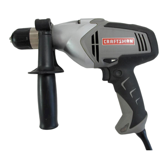
Page 8: Product Specifications
PRODUCTSPECIFICATIONS Chuck............in. Keyless No Load Speed ..........0-800/min. Switch ........Variable Speed/Reversible Input ........ 120 V, 60 Hz, AC only, 5.5 Amps Maximum Torque ......... Maximum 266 in.lb. Net Weight ..............5 Ibs. LEVELS DiRECTiONOF ROTATION SELECTOR (FORWARD / REVERSE) AUXILIARY HANDLE LOCK=ON... -
Page 9: Packing List
UNPACKING WARNING: If any parts are missing do not operate This product has been shipped completely assembled. this tool until the missing parts are replaced. Failure [] Carefully remove the tool and any accessories from the to do so could result in possible serious personal box. - Page 10 VARIABLESPEEDSWITCH DiRECTiONOF VARIABLE SPEED ROTATION SELECTOR SWITCH See Figure 2. (FORWARD/REVERSE/ To turn the drill ON, depress the variable speed switch. To CENTER LOCK) REVERSE turn it OFF, release the switch. VARIABLE SPEED See Figure 2. The variable speed switch delivers higher speed and torque with increased trigger pressure and lower speed with decreased trigger pressure.
-
Page 11: Operation
REMOVING BITS WARNING: Always unplug the tool when installing See Figure 4. or removing bits, adjusting settings, or when the tool [] Unplug the drill. is not in use. Failure to unplug the tool may result in [] Rotate the chuck sleeve clockwise to open the chuck accidental starting and serious personal injury. -
Page 12: Lock-On Button
LOCK-ON BUTTON DRILLING See Figures 8 - 9. See Figure 7. Levels are located on the top and end of the motor hous- This drill is equipped with a lock-on feature, which is ing to help keep the drill bit level during use. convenient for continuous drilling for extended periods of time. -
Page 13: Top View
WARNING: Be prepared for binding at bit break- through. When these situations occur, the drill has LEVEL a tendency to grab and kick in the opposite direc- tion and could cause loss of control when breaking through material. If not prepared, this loss of control can result in possible serious injury. -
Page 14: Maintenance
REMOVAL WARNING: When servicing, use only identical See Figures 10- 12, Craftsman replacement parts. Use of any other parts The chuck may be removed and replaced with a new one. may create a hazard or cause product damage. [] Unplug the drill. -
Page 15: Accessories
MALLET TO RETIGHTEN A LOOSE CHUCK The chuck may become loose on the spindle and develop a wobble. Also, the chuck screw may become loose, causing the chuck jaws to bind and prevent them from closing. To tighten: [] Unplug the drill. [] Open the chuck jaws.
Need help?
Do you have a question about the 315.101150 and is the answer not in the manual?
Questions and answers