Table of Contents
Advertisement
Available languages
Available languages
Quick Links
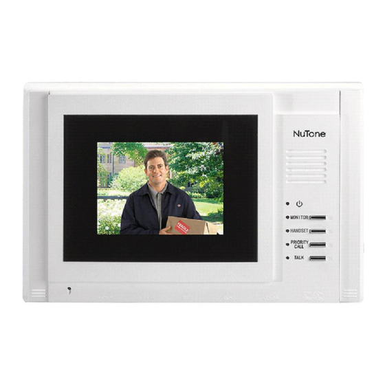
Video Door Answering System
Model VSM4RK
INSTALLATION INSTRUCTIONS
This booklet contains information for installing the In-wall
Monitor. All system wiring and rough-in frames should be
installed before mounting and wiring the master station.
Refer to the installation instructions packaged with the
rough-in frames for detailed wiring information.
TO REGISTER THIS PRODUCT, VISIT WWW.NUTONE.COM
READ & SAVE THESE INSTRUCTIONS!
For more detailed information on wiring and mounting other
system components (i.e., optional camera, rough-in.), refer
to the installation instructions packaged with the separate
components.
INSTALLATION INSTRUCTIONS
Advertisement
Chapters
Table of Contents

Subscribe to Our Youtube Channel
Related Manuals for NuTone VSM4RK


Summary of Contents for NuTone VSM4RK
-
Page 1: Installation Instructions
(i.e., optional camera, rough-in.), refer installed before mounting and wiring the master station. to the installation instructions packaged with the separate Refer to the installation instructions packaged with the components. rough-in frames for detailed wiring information. TO REGISTER THIS PRODUCT, VISIT WWW.NUTONE.COM... -
Page 2: Important Safety Instructions
Caution RISK OF ELECTRIC SHOCK DO NOT OPEN CAUTION: TO PREVENT THE RISK OF ELECTRIC SHOCK, DO NOT REMOVE COVER (OR BACK). NO USER-SERVICEABLE PARTS INSIDE. REFER SERVICING TO QUALIFIED SER- VICE PERSONNEL. WARNING: TO REDUCE THE RISK OF FIRE OR ELECTRIC SHOCK, DO NOT EXPOSE THIS APPARATUS TO RAIN OR MOIS- TURE. - Page 3 IMPORTANT SAFETY INSTRUCTIONS READ THESE INSTRUCTIONS — All the safety and outlet. Do not defeat the safety purpose of the polarized operating instructions should be read before the product plug. is operated. 12. POWER-CORD PROTECTION — Power-supply cords RETAIN INSTRUCTIONS — The safety and operating should be routed so that they are not likely to be walked instructions should be retained for future reference.
- Page 4 the operation instructions. Adjust only those controls the sam characteristics as the original part. Unauthorized that are covered by the operating instruction, as an substitutions may result in fire, electric shock or other improper adjustment of other controls may result in hazards.
-
Page 5: Table Of Contents
Table of Contents VSM4RK REPRESENTATIVE WIRING ILLUSTRATION ........5 INSTALLATION . -
Page 6: Installation
The monitor and camera is designed to be used with category 5 or category 6; no other cable should be used. The • use of wire other than category 5 or category 6 cable will void all NuTone warranties and may result in faulty installation and improper operation. -
Page 7: Optional Handset Wiring
AND TV/MONITOR MUST BE PLACED AT LEAST 12 INCHES FROM ANY A.C. POWER WIRING. AVOID RUNNING INTERCOM WIRES PARALLEL TO A.C. POWER WIRING. IMPORTANT: Never use any camera other than NuTone camera supplied with the VSM4RK or the Camera and/or Monitor will be damaged. Only ONE NuTone camera can be connected to the monitor. -
Page 8: Attaching Monitor Mounting Brackets At The Monitor Rough-In
4. Attach each of the twisted pair of wires to the corresponding terminal on the back of the camera. Tighten each screw securely. Mounting Screw and flat washer 5. Dress extra cable and position camera into rough-in. 6. Fully seat the camera into the rough-in. Open the upper and lower access doors. -
Page 9: Connecting Camera At The Monitor
2. Repeat step 2 for the remaining mounting bracket. Existing Construction 1. Position one of the two mounting brackets (ears out) and use two (2) #6 x 3/4" screws (supplied) to attach the brack- et to the rough-in. Before tightening, slide the bracket so it is flush with the wall surface. Tighten the screws. 2. -
Page 10: Connecting Power And Mounting The Monitor
the VSA4S handset for mounting and wiring instructions. 1. Strip approx 2" of outer protective jacket from the category 5 or category 6 cable. 2. Separate and strip approx. 1/2" of insulation from each of the eight wires in the cable. Twist the following cables together: •... -
Page 11: Powering Up The System
4. Insert and lightly fasten the four (4) #6 x 3/4" screws (supplied) into the monitor panel and VRM4R rough- in. Center and level the monitor panel then tighten each screw securely. 5. Replace the screw covers on each side of the monitor. Powering Up the System Once all connections throughout the system have been checked, apply power to the monitor by turning on the circuit breaker that supplies power to the monitor. - Page 12 • Consult the dealer or an experienced radio/TV techni- FCC Information Part 15 Rules cian for help. This equipment has been tested and found to comply with the FCC Warning – This equipment may generate or use radio fre- limits for a Class B digital device, pursuant to Part 15 of the quency energy.
- Page 13 être achevée avant le montage et option), reportez-vous aux directives d’installation fournies le câblage de la station principale. Reportez-vous aux direc- avec chaque composant. tives d’installations fournies avec les boîtiers pour tous les détails de câblage. POUR ENREGISTRER CE PRODUIT, VISITEZ WWW.NUTONE.COM...
- Page 14 Avertissement RISQUE DE CHOC ÉLECTRIQUE NE PAS OUVRIR AVERTISSEMENT: POUR PRÉVENIR LE RISQUE DE DÉCHARGE ÉLECTRIQUE, NE PAS RETIRER LE COUVERCLE (NI LA PLAQUE ARRIÈRE). NE CONTIENT AUCUNE PIÈCE POUVANT TRE RÉPARÉE PAR L’UTILISA- TEUR. CONFIER TOUTE RÉPARATION À UN TECH- NICIEN PROFESSIONNEL.
- Page 15 IMPORTANTES DIRECTIVES DE SÉCURITÉ 1. LISEZ CES DIRECTIVES — Veuillez lire toutes les direc- l’autre). La fiche ne peut être insérée que d’une seule tives relatives à la sécurité et au fonctionnement avant d’u- manière dans la prise. Ce dispositif assure votre sécurité. Si tiliser cet appareil.
- Page 16 B. Du liquide ou des corps étrangers ont pénétré dans le bien servir de pièces d’origine ou de pièces ayant les boîtier de l’appareil. mêmes caractéristiques que celles d’origine. Des pièces non autorisées risquent de vous exposer à un incendie, à C.
- Page 17 Table des matières SCHÉMA DE CÂBLAGE REPRÉSENTATIF DU VSM4RK..............5 INSTALLATION ............................6 Contenu de la boîte ..........................6 Précautions et lignes directrices .......................6 Spécifications de câblage ........................6-7 Câblage de la caméra..........................7 Câblage du combiné en option .........................7 Câblage et montage de la caméra ......................7-8 Fixation des supports de montage du moniteur au boîtier du moniteur..........8-9 Connexion de la caméra au moniteur.......................9 Connexion du combiné...
-
Page 18: Installation
PRÉCAUTIONS ET LIGNES DIRECTRICES Le VSM4RK de NuTone a été conçu de manière à pouvoir être installé facilement. Veuillez lire TOUTES les directives d’in- stallation, lignes directrices et précautions. Tout non-respect de ces directives et toute erreur de câblage peuvent entraîner la défaillance de l’appareil;... -
Page 19: Câblage Du Combiné En Option
EN PARALLÈLE AVEC DES CÂBLES D’ALIMENTATION c.a. IMPORTANT: N’utilisez aucun autre combiné que le combiné VSA4S de NuTone pour prévenir tout dommage au combiné, à la caméra ou au moniteur. UN seul combiné VSA4S de NuTone en option peut être connecté à ce moniteur. -
Page 20: Fixation Des Supports De Montage Du Moniteur Au Boîtier Du Moniteur
4. Fixez chaque paire de fils torsadées sur les bornes à vis correspondantes à l’arrière de la caméra. Serrez chaque vis à fond. Vis de montage et rondelle plate 5. Remettez en place la longueur de câble en trop et positionnez la caméra dans le boîtier encastrable. -
Page 21: Connexion De La Caméra Au Moniteur
Bâtiment existant 1. Positionnez un des deux supports de montage (pattes vers l’extérieur) et utilisez deux (2) vis n o 6 x 3/4 po (fournies) pour fixer le support au boîtier encastrable. Avant de serrer, faites glisser le support pour l’aligner avec la surface du mur. Serrez les vis. -
Page 22: Connexion De L'alimentation Et Montage Du Moniteur
1. Dénudez une longueur approximative de 2 po de la gaine protectrice extérieure du câble de catégorie 5 ou 6. 2. Séparez et dénudez une longueur approximative de 1/2 po de chacun des huit fils contenus dans le câble./ Tordez les paires de fils ci-dessous ensemble: •... -
Page 23: Mise En Marche Du Système
4. Insérez et serrez partiellement les quatre (4) vis n o 6 x 3/4 po (fournies) dans le panneau du moniteur et le boîtier encastré VRM4R. Centrez et mettez à niveau le panneau du moniteur, puis serrez à fond chacune des vis. - Page 24 • Consultez le vendeur ou un technicien radio/TV com- Règlement de la FCC, Partie 15 pétent. Cet appareil a été testé et reconnu conforme aux limites Mise en garde de la FCC - Ce matériel peut générer ou utiliser prévues pour des appareils numériques de classe B, tel que des fréquences radio.
Need help?
Do you have a question about the VSM4RK and is the answer not in the manual?
Questions and answers