
Related Manuals for Dunkirk 3ES1 00C


Summary of Contents for Dunkirk 3ES1 00C
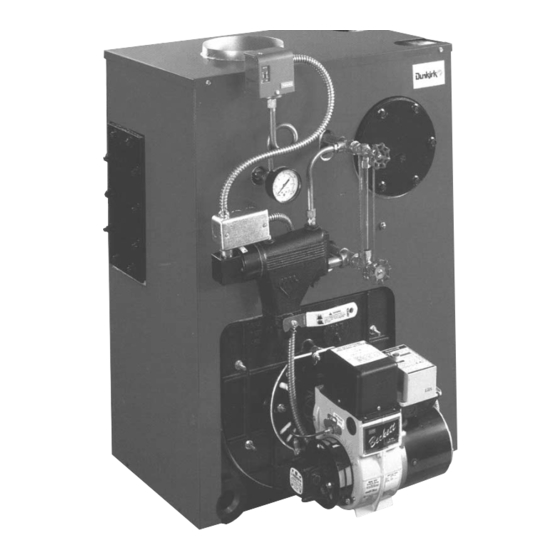
- Page 1 O|L-F|REDCAST |RON STF.AM Installation • Operation • RepairParts Theseinstructions m ustbe affixedon or adjacent t o theboiler.DUNKIRKBOILERS DUNKIRK, N EWYORK14048- 716 366-5500 MEMBER: The llydronies Institute...
- Page 2 I/2" TANKLESS I/2" HEATER 5/4" ASNE PRESSURETROL 2-I/2" PRESSURE GAUGE SUPPLY SAFETY COMBINATION iq°p VALVE 3/4 _ NPT i-i/2" _LOW UMIT SKIM TAPPING CONTROL 27" COIL PLATE WATER 1-1/2" IJNE RETURN ,-V2 ° NPTi RETURN REAR LEFT SIDE FRONT EMPIRE OIL-FIRED STEAM BOILER RATINGS BOILER MODEL NO.
- Page 3 Rulesfor Safe Installationand Operation 1. Readthe Owner'sManualfor SafeOperationcarefully. F ailureto follow 5. Be certain oil burnernozzleis size required.Overfiring will result in the rulesfor safeoperation andtheinstructions c ancausea malfunction o f earlyfailureofthe boilersections. T hiswill causedangerous operation. the boiler and result in death, _rious bodily injury, and/or property 6.
- Page 4 Locatingthe Boiler If your boiler is partof a plannedheatingsystem,locateit as nearlyas 6. The floor suppo_ng the boiler must be non-combustible. If it is possiblewhereshownon yourplan. If boiler is to be part of an existing combustible, placethe boileron 2" cladlitepad.The pad mustbe under theentireboilerto protect t hefloor.
- Page 5 Fresh Air for Combustion WARNING NOTE If you use a fireplaceor a kitchen or bathroomexhaustfan, you Be sure to provide enough fresh air for combustion. Enough air ensures shouldinstallan outsideair intake.Thesedeviceswill robthe boiler proper combustion and assures that no hazard will develop due to andwaterheaterof combustion air.
- Page 6 Boilers With Tankless Heater Coil Boilersmaybefactorypackaged with a tanklessheatercoil.Theuseof this coileliminates the needfor a hot waterstorage tank.Instantaneous heatingof water in the coil will providea flow of hotwaterfor domesticuse - if proper watersupplylinecontrolsare used. IMPORTANT Do not usea tanklesscoil if yourwateris excessively hardwith limeor otherdeposits whichwillaccumulate insidethecoil.
- Page 7 Installation-System Piping between suchsafetyvalvesandthe atmosphere. Installation of thepop Thenearboilerpiping, t hat is the pipingaround the boiler,mustbe considered safetyvalveshallconformto therequirements o f theANSI/ASME Boiler as partof the boilerfor proper waterlevelcontrol,andto producedrysteam. and Pressure Vessel Code, Section IV The manufacturer i s not Correctnearboilerpipingis crucial t o the properoperation ofthe boilerand responsible foranywaterdamage.
- Page 8 All boilersin gravityreturnsystems mustbeequipped witha Hartford 5. Forinstailers choosing to usebothsupplytappings,Figure8A showsthe Loopasshownin Figures8 and 8A. correctwayto pipethis system.Figure8B showsthewrongwayto pipe a header with tworisers. Whenpipingthevertical r isersfromtheboilerto theheader, t he bottom of the headermustbe a minimum of 24 inchesabovethewater level , Headersmust be fitted with header offsetsor swingjoints, or be lineanthe rightsideofthe boiler(i.e.51 inchesabovethefloor).
- Page 9 THIS, PIPING tS INCORRECT TO SHOW COMMON MISTAKES © 12. The near boiler piping shall includea 1 1/2" ball valve in the return B. Whenthis boileris connected to heatingcoilslocatedin air handling unit., pipingas shownin Figure8A far bottomblowdawn anddraining. where they may be exposedto refrigeratedair circulation,the piping systemshall be equippedwith flow controlvalves or other automatic 13.
- Page 10 Chimneyand ChimneyConnection CHECKYOURCHIMNEY Followlocalcodes.In the absence of localcodes,followANSI/NFPA 31 MUST BE REQUIRED MIN* Installation o f OilBurning Equipment, latestedition. IMUM HEIGHT, MUST AT LEAST 3 FT. HIGHER This is a very important p artof yourheatingsystem.Noboiler,however THAN HIGHEST PART efficient i ts design, c anperform satisfactorily if thechimney thatservesit is PASSAGE THROUGH ROOF.
- Page 11 Doublethe systempressuredropas a safetyfactor, detailson waterfeederselection,recommended p ipingarrangement, and resulting in the rulethat the cut-insettingshouldneverbe lessthantwicethe start up procedures. Dunkirk Radiator supports McDonnell-Miller's systempressure drop. recommendation to arrangethe installed pipingso a brokenuniontest can Thedifferential set#oint i s thesteampressure required at theterminal h eating be implemented.
-
Page 12: Fillingsystemwith Water
STEAMVENTS scaldinghotnormerelytepid.The FlowRegulator i s placedin thecoldwater line to thecoil. It assuresa steadyflow of watersothat the coilcanproperly Beforea steamsystemwill operateproperly, s uitablesteamventsmustbe heatit. It prevents"spurts" of "half-heated" water.Thisisimportant wherethe installedin eachradiatoras wellas the returnmain.Somesystemsrequire waterpressureis excessively highor variable.TheWaterTempering Valve steamtrapsin thereturnlineat theradiation unit. is a tee whichis connected at a junctionbetween the hotwaterlinefrom the The"Hartfordloop"is a pipingarrangement whichmustbeincluded(Fig.8) coiland a coldwaterbranchfromthesupplyline.It mixeshotandcoldwater... - Page 13 Maintaining Your Boiler It is caused by anycombination ofthefollowing: Checkthe water level every day or two.Verify the water tine shown by 1. Threading oil andorganicmatterin the boilerwater.(Mineral o il, or core operatingthe drain valvean the gauge.Be sure top and bottom valves sanddoesnotcausesurging.) on gaugeare alwaysopen so that actual water levelwill be shown at all times,...
- Page 14 Oil Boiler/Burner CleaningInstructions 1. Shutoff alIelectricaI p owertotheboiler/burner a ndshut offfuel supply. 2. Remove the sheetmetalsmokepipefrom thetop d the boiler.Inspect pipe and chimneyfor signs of corrosionand deterioration. Cleanbase ofchimney. 3. Remove topjacketpanel. 4. Remove the two brasswingnutsholding theflueccllector f op. oooooooooooo ooooooo 5.
- Page 15 me_javowal i r_o_nven_ and servi_ calls _ ch_ these potn(s _m c_l for _r_ce. What: to Reset themsostat above room tem_raIu Cean all flue passages and _'he'_nt pipe, Nave burner c_ea_d and read ueted, Bu _ler may not _ iitng at proper C_eek _e_f_e size if there is _y doubt, re[@ Have burner adjusted...
- Page 16 OPTIONAL LOW LIMIT CONTROL FOR BOILERS OIL BURNER WITH TANKLESS COIL PRIMARY RELAY HONEYWELL PRESSURETROL _ COLORCODE PART NO. 146-62-015 TO 24v THERMOSTAT BK = BI_CK BL = BLUE W = WHITE G = GREEN i_ =WIRE NUT LOW VOLTAGE WiRiNG HARNESS NOT FURNISHED pART NO, - 146-34-O47 _PRESSURETROL TO LWC.O...
- Page 18 "_p_r_ Tsr_kle_ _i_ K_t4340_14 (ir_l:_s coJ_, _ 8{, and b_l_)
- Page 19 (1 _69BI0!
- Page 20 SUGGESTED NOZZLES AND SETTINGS FOR BECKETT AFG-M OIL BURNER SERIES PUMP BOILER NOZZLE ACTUAL HEAD PRESSURE BURNER MODEL ADJUSTMENT SHUTTER BAN D (psig) MODEL 0,85-60°W 1.00 3ES1.00(C) AFG-50MB 1,10-70°B 1.25 3ES1,25(0) AFG-50MD 1,20-70°B 1.35 3ES! .35(C) AFG-50MD 1,25-60°B 1.50 4ES1,50(C) AFG-50MD 4ES1,75(C) 1,50-60°B...
Need help?
Do you have a question about the 3ES1 00C and is the answer not in the manual?
Questions and answers