Table of Contents
Advertisement
INSTALLATION
INSTRUCTIONS
These instructions
must be affixed on or adjacent to the boiler
Dml'v' ¢
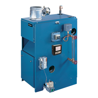
MODEL PVSB
Continuous
Pilot
Gas-Fired
Steam
Boilers
These Gas-Fired Water Boilers are low pressure, sectional
cast iron boilers Designed Certified by C.S.A. (Canadian
Standards Association) for use with Natural and Propane
Gases. They are constructed and hydrostatically tested for a
maximum working pressure of 50 psi (pounds per square
inch) in accordance with AS.ME.
(American Society of
Mechanical Engineers) Boiler and Pressure Vessel Code
Section IV Standards for cast iron heating boilers.
MODEL PSB
Electronic
Intermittent
Ignition
Warning:
Improper
installation,
adjustment,
alteration,
service
or maintenance
can cause injury or
property
damage.
Refer to this manual.
For assistance
or additional
information
consult
a qualified
installer,
service agency
or the gas supplier
Advertisement
Table of Contents


Need help?
Do you have a question about the PVSB and is the answer not in the manual?
Questions and answers