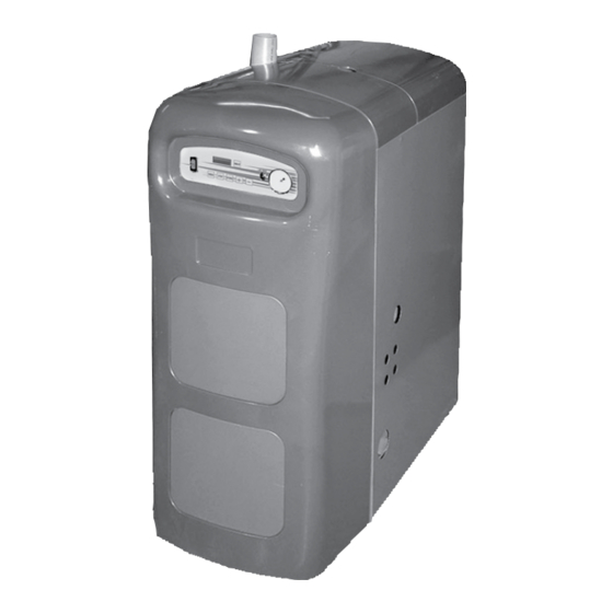
Dunkirk Q95M-200 Installation Manual
Gas-fired direct vent modulating hot water boiler
Hide thumbs
Also See for Q95M-200:
- Installation, operation & maintenance manual (52 pages) ,
- Installation, operation & maintanance manual (48 pages) ,
- Installation manual (37 pages)

Related Manuals for Dunkirk Q95M-200


Summary of Contents for Dunkirk Q95M-200
- Page 1 DUNKIRK BOILERS 85 Middle Rd. An ISO 9001-2000 Certified Company Dunkirk, NY 14048 www.dunkirk.com P/N 240006103D, Rev. 1.1 [04/06]...
-
Page 3: Table Of Contents
GAS-FIRED DIRECT VENT MODULATING HOT WATER BOILER INSTALLATION MANUAL P/N# 240006103D, Rev. 1.1 [04/06] • Printed in USA • Made In USA TABLE OF CONTENTS I - INTRODUCTION This appliance is a gas-fired direct vent modulat- Introduction.......... ing cast aluminum hot water boiler. A revolutionary Safety Symbols........ -
Page 4: Safety Symbols
II - SAFETY SYMBOLS AND WARNINGS The following defined symbols are used throughout this manual to notify the reader of potential hazards of varying risk levels. DANGER CAUTION Indicates an imminently hazardous situation Indicates a potentially hazardous situation which, if not avoided, will result in death or which, if not avoided, may result in minor or serious injury. -
Page 5: Boiler Ratings And Capacities
IV - BOILER RATINGS AND CAPACITIES TABLE 1: SEA LEVEL RATINGS - NATURAL AND PROPANE GASES Boiler Input Rate Heating Capacity Net I=B=R Rating AFUE Flue Diameter Shipping (MBH) (MBH) (MBH) (1)(2) High Fire 2” CPVC & 3” PVC 284 lbs. Low Fire 1 MBH = 1,000 Btuh (British Thermal Units Per Hour) Heating Capacity and AFUE (Annual Fuel Utilization Efficiency) are based on DOE (Department of Energy) test procedures. -
Page 6: Before Installing The Boiler
Installers - Follow local regulations with respect LOCATING THE BOILER to installation of Carbon Monoxide Detectors. Follow maintenance recommendations in this 1. Select a location which is level, central to the pip- manual. ing systems served and as close to the vent and air intake terminals as possible. - Page 7 operation and service (circulator replacement, con- This boiler requires a dedicated direct vent system. trol replacement, etc.). In a direct vent system, all air for combustion is taken directly from outside atmosphere, and all flue 8. The boiler must be located where ambient room products are discharged to outside atmosphere.
- Page 8 WARNING Figure 5 - Concentric Vent Roof Installation (Continued from previous page) phates, bromides and iodides. These ele- ments are found in aerosols, detergents, bleaches, cleaning solvents, salts, air fresheners, paints, adhesives, and other household products. • Locate combustion air inlet as far away as possible from swimming pool and swim- ming pool pump house.
-
Page 9: Placing The Boiler
in which the appliances remaining connected FOUNDATION REQUIREMENTS to the common venting system are located and other spaces of the building. Turn on clothes Boiler must be placed on level surface. Boiler is dryer and any appliance not connected to the NOT to be installed on carpeting. -
Page 10: Near Boiler Piping
VII - NEAR BOILER PIPING IMPORTANT: For piping examples using the Gas-Fired Direct Vent Modulating Hot Water Boiler, see the Piping Appendix in Section XIV of this manual. CAUTION ter supply is from a well or pump, a sand strainer should be installed at the pump. -
Page 11: Combustion Air And Vent Pipe
between such safety valve and the atmosphere. FILLING CONDENSATE TRAP WITH WATER Installation of the safety relief valve shall conform to ANSI/ASME Boiler and Pressure Vessel Code, IMPORTANT: On initial start up the condensate Section IV. The manufacturer is not responsible for trap must be manually filled with water. - Page 12 2. Combustion air and vent pipe fittings must 1. Combustion air piping to be pitched back to conform to American National Standards Insti- boiler at minimum ¼” per foot from vent terminals tute (ANSI) standards and American Society so that all moisture in vent piping drains to boiler. for Testing and Materials (ASTM) standards Pipes must be pitched continuously with no sags D1784 (schedule-40 CPVC), D1785 (schedule-...
-
Page 13: Gas Supply Piping
or below, electric meters, gas meters, regula- 7. After pipes have been cut and pre-assem- tors, and relief equipment. bled, apply cement primer to pipe fitting socket and end of pipe to insertion mark. Quickly apply If multiple terminations are used, there must be approved cement to end of pipe and fitting sock- a minimum of 12”... - Page 14 In order for proper operation of the boiler, it is rec- 2. Use pipe joint compound suitable for liquefied ommended that the line pressure be within the min- petroleum gas on male threads only. imum and maximum values in Table 5. 3.
-
Page 15: Electrical Wiring
X - ELECTRICAL WIRING IMPORTANT: Wiring diagrams for the Gas-Fired Direct Vent Modulating Hot Water Boiler can be found in Section XIII of this manual. WARNING 2. Route all low voltage wires through grommet- ed opening on the right jacket panel. For your safety, turn off electrical power sup- ply at service panel before making any elec- THERMOSTAT... -
Page 16: Controls And Accessories
XI - CONTROLS AND ACCESSORIES This section provides a brief description of the key into the combustion chamber where combustion can controls and accessories found in this boiler. See the begin and then out the exhaust vent where the com- Repair Parts Manual (P/N# 240006107) for illustra- bustion products are discharged to the outdoors. - Page 17 sense flame during operation. The DSI is a durable, CASTING TEMPERATURE SAFETY SWITCH reliable component that resists breakage due to handling or inadvertent impact with other objects. In the event of lack of or loss of water in the boiler, the casting temperature safety switch (230°F set- MANUAL RESET LOW WATER CUT OFF point) installed on the top of the aluminum boil-...
-
Page 18: Maintenance And Cleaning
normally closed switch opens if there is a blockage pipe as the valve discharge opening to an open in the combustion air intake or exhaust vent pipes. drain, tub or sink, or other suitable drainage point not subject to freezing, in accordance with ASME DRAIN VALVE specifications. - Page 19 • Checking all gasketed joints for leakage including flushing of float type devices. Refer to and tightening bolts or replacing gaskets as low water cut off manufacturer’s specific instruc- needed. tions. • Removing jacket front and top panels, check- ANNUAL SHUT DOWN PROCEDURE ing for piping leaks around relief valve and other fittings, and repairing if found WITH- 1.
- Page 20 • Remove five nuts and remove blower adapt- stall five nuts but do not tighten. Reinstall er assembly, burner, and gaskets. igniter and igniter gasket and fasten with two screws. Tighten five nuts holding blower • Aluminum oxide deposits are water soluble adapter assembly.
-
Page 21: Boiler Wire Diagram
XIII - BOILER WIRE DIAGRAM... -
Page 22: Piping And Wiring Appendix
XIV - PIPING AND WIRING APPENDIX SINGLE ZONE SYSTEM WITH DOMESTIC HOT WATER PRIORITY... - Page 23 XIV - PIPING AND WIRING APPENDIX SINGLE ZONE SYSTEM WITH DOMESTIC HOT WATER PRIORITY...
- Page 24 XIV - PIPING AND WIRING APPENDIX MULTIZONE PIPING WITH ZONE VALVES AND DOMESTIC HOT WATER PRIORITY (WITH ZONE VALVE)
- Page 25 XIV - PIPING AND WIRING APPENDIX MULTIZONE PIPING WITH ZONE VALVES AND DOMESTIC HOT WATER PRIORITY (WITH ZONE VALVE)
- Page 26 XIV - PIPING AND WIRING APPENDIX MULTIZONE SYSTEM WITH ZONE VALVES AND DOMESTIC HOT WATER PRIORITY (WITH CIRCULATOR)
- Page 27 XIV - PIPING AND WIRING APPENDIX MULTIZONE SYSTEM WITH ZONE VALVES AND DOMESTIC HOT WATER PRIORITY (WITH CIRCULATOR)
- Page 28 XIV - PIPING AND WIRING APPENDIX MULTIZONE SYSTEM WITH CIRCULATORS AND DOMESTIC HOT WATER PRIORITY...
- Page 29 XIV - PIPING AND WIRING APPENDIX MULTIZONE SYSTEM WITH CIRCULATORS AND DOMESTIC HOT WATER PRIORITY...
- Page 30 XIV - PIPING AND WIRING APPENDIX PRIMARY/SECONDARY PIPING WITH CIRCULATORS AND DOMESTIC HOT WATER...
- Page 31 XIV - PIPING AND WIRING APPENDIX PRIMARY/SECONDARY WIRING WITH CIRCULATORS AND DOMESTIC HOT WATER...
- Page 32 XIV - PIPING AND WIRING APPENDIX PRIMARY/SECONDARY MULTIZONE SYSTEM PIPING WITH ZONE VALVES AND DOMESTIC HOT WATER (WITH ZONE VALVE)
- Page 33 XIV - PIPING AND WIRING APPENDIX PRIMARY/SECONDARY MULTIZONE SYSTEM WIRING WITH ZONE VALVES AND DOMESTIC HOT WATER (WITH ZONE VALVE)
- Page 34 XIV - PIPING AND WIRING APPENDIX PRIMARY/SECONDARY PIPING WITH ZONE VALVES AND DOMESTIC HOT WATER (WITH CIRCULATOR)
- Page 35 XIV - PIPING AND WIRING APPENDIX PRIMARY/SECONDARY WIRING WITH ZONE VALVES AND DOMESTIC HOT WATER (WITH CIRCULATOR)
- Page 36 XIV - PIPING AND WIRING APPENDIX BYPASS PIPING (AUTOMATIC MIXING VALVE)
- Page 37 XIV - PIPING AND WIRING APPENDIX BYPASS PIPING (FIXED LOW TEMP. ONLY)
- Page 38 XIV - PIPING AND WIRING APPENDIX BYPASS PIPING (4-WAY VALVE OPTION WITH CIRCULATOR ON SUPPLY)
Need help?
Do you have a question about the Q95M-200 and is the answer not in the manual?
Questions and answers