Table of Contents
Advertisement
Models
3EWC0.80(T)
4EWC1.00(T)
4EWC1.25(T)
5EWC1.55(T)
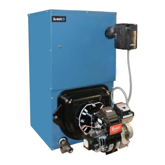
EMPIRE
OIL-FIRED CAST IRON
HOT WATER
INSTALLATION, OPERATION
& MAINTENANCE MANUAL
Maximum Allowable
Working Pressure 50 psi.
2201 Dwyer Avenue, Utica, NY 13501
PN 240013012 REV. B [12/15/2020]
Manufactured by:
ECR International Inc.
Tel. 800 325 5479
www.ecrinternational.com
Advertisement
Table of Contents

Related Manuals for Dunkirk EMPIRE 3EWC0.80


Summary of Contents for Dunkirk EMPIRE 3EWC0.80
- Page 1 EMPIRE OIL-FIRED CAST IRON HOT WATER INSTALLATION, OPERATION & MAINTENANCE MANUAL Models 3EWC0.80(T) 4EWC1.00(T) 4EWC1.25(T) 5EWC1.55(T) Maximum Allowable Working Pressure 50 psi. Manufactured by: ECR International Inc. 2201 Dwyer Avenue, Utica, NY 13501 Tel. 800 325 5479 www.ecrinternational.com PN 240013012 REV. B [12/15/2020]...
-
Page 2: Table Of Contents
CONTENTS INTRODUCTION Empire Water boiler is a natural draft oil fired hot water Boiler Ratings And Capacities ....3 boiler comprised of cast iron sections. Empire Water Safety Notices ........4 boiler is available with 3, 4, or 5 cast iron sections. These sections are held together by cast iron push nipples. -
Page 3: Boiler Ratings And Capacities
BOILER RATINGS AND CAPACITIES Figure 1 - Dimensions BOILER RATINGS AND CAPACITIES ‡NET DIMENSIONS BOILER INPUT MINIMUM **HEATING AHRI (inches) MODEL NO. A.F.U.E. CHIMNEY CAPACITY RATING Without SEC. SIZE/ *Mbh WATER +gph *Mbh 8” X 8” X 15” 14 ½ Tankless Coil HEIGHT *Mbh... -
Page 4: Safety Notices
SAFETY NOTICES Become familiar with symbols identifying potential hazards. FOR YOUR SAFETY READ BEFORE OPERATING This is the safety alert symbol. Symbol alerts DANGER you to potential personal injury hazards. Obey all safety messages following this symbol to avoid possible injury or death. DANGER Indicates a hazardous situation which, if not avoided, WILL result in death or serious injury. -
Page 5: Safe Installation And Operation
SAFE INSTALLATION AND OPERATION Be certain oil burner nozzle is the size required. Over- WARNING firing will result in early failure of the boiler sections. This will cause dangerous operation. Fire, Explosion, burn, scald hazard. Use only number 2 fuel oil. Do not use gasoline, kerosene, crankcase Do not vent this boiler into enclosed space. -
Page 6: Locating The Boiler
LOCATING THE BOILER Complete Prior To Installing Boiler. Place boiler in location centralized with the piping system and as close to chimney as possible. A. Verify you have selected the right size boiler with proper capacity. AHRI rating of boiler selected Boiler must be level. - Page 7 LOCATING THE BOILER Figure 3 - Boiler With Piping System PN 240013012, Rev. B [12/15/2020]...
-
Page 8: Fresh Air For Combustion
FRESH AIR FOR COMBUSTION EXAMPLE 2: Boiler Located in Confined Space WARNING Asphyxiation, fire hazard. Do not obstruct air All Air from Inside the Building: Confined openings to combustion area. Follow instructions space shall be provided with two permanent openings below, to maintain adequate combustion air. - Page 9 FRESH AIR FOR COMBUSTION All Air from Outdoors: Confined space shall 3. When communicating with outdoors through be provided with two permanent openings, one horizontal ducts, each opening shall have commencing within 12 inches of top and one minimum free area of one square inch per 2,000 commencing within 12 inches of bottom of enclosure.
-
Page 10: System Piping
SYSTEM PIPING Installation of boiler for new heating system, Figure 6a - Safety Relief Valve Installation Install all of radiation units (panels, radiators, baseboard, or tubing) and supply and return mains first. After all heating system piping and components have been installed, make final connection of system piping to boiler. - Page 11 SYSTEM PIPING Low Design Water Temperature Systems (Below 140° Figure 7 - Bypass Piping Arrangement Diagram F) And Large Water Content Systems • Significant condensation may form in this boiler and/ > LOW DESIGN WATER TEMPERATURE or venting system if boiler is operated with return SYSTEMS temperatures of less than 120°F.
- Page 12 SYSTEM PIPING Figure 8 - System Piping Arrangement Zoning With Zone Valves > CIRCULATOR ON SUPPLY PIPING PUMPS AWAY FROM EXPANSION TANK N O T E : C I R C U L A T O R C A N A L S O B E INSTALLED ON RETURN PIPING.
- Page 13 SYSTEM PIPING Figure 9 - System Piping Arrangement Zoning With Circulators > CIRCULATOR ON SUPPLY PIPING PUMPS AWAY FROM EXPANSION TANK > PIPING ARRANGED FOR “POWER PURGING” AIR OUT OF SYSTEM PIPING, REFER TO THIS MANUAL’S SECTION ON “FILLING THE SYSTEM WITH WATER” OPTION #1 PN 240013012, Rev.
- Page 14 SYSTEM PIPING Figure 10 - System Piping Arrangement Alternate Near Boiler Piping > PER THIS MANUAL, USE OPTION #2 IN > DIAPHRAGM EXPANSION TANK MOUNTED “FILLING THE SYSTEM WITH WATER” OFF THE BOILER > THIS PIPING ARRANGEMENT CAN BE USED >...
- Page 15 SYSTEM PIPING Tankless Coil Piping Arrangement Burner Tankless Boiler Input Input Rating DANGER Model (MBH) Rate (gph) (gpm)‡ Scald, Burn Hazard! Temperatures exceeding 120°F 3EWC0.80T 0.80 3.05 will cause severe burns or death. Use of water 4EWC1.00T 1.00 3.25 tempering device or mixing valve may be required by the Authority having jurisdiction, follow all codes 4EWC1.25T 1.25...
-
Page 16: Antifreeze In The System
ANTIFREEZE IN THE SYSTEM Antifreeze added to boilers must be nontoxic, and PIPING WATER VOLUMES must be of type specifically intended for use in closed hydronic heating systems. Under no circumstances should COPPER PIPE STEEL PIPE PIPE SIZE automotive antifreeze be used. Antifreeze used in any FACTOR FACTOR boiler may reduce capacity by 10% or more and increase... - Page 17 CHIMNEY AND CHIMNEY CONNECTIONS WARNING Fire Hazard! Maintain minimum vent pipe clearance of 9” from surface of vent to wood and other combustible materials. Failure to comply could result in death or serious injury. Chimney Connector And Draft Regulator • Venting the boiler requires 6” diameter chimney connector pipe and use of manufacturer provided draft regulator.
-
Page 18: Typical Chimney Connection
TYPICAL CHIMNEY CONNECTION Figure 12 - Typical Chimney Connection MINIMUM HEIGHT: MUST BE AT LEAST 3 FT (.9m) HIGHER THAN HIGHEST PART OF PASSAGE THROUGH ROOF. MUST BE AT LEAST 2 FT HIGHER THAN ANY NEIGHBORING OBJECT WITHIN 10 FT. MUST HAVE AN UNOBSTRUCTED TOP OPENING. -
Page 19: Electrical Connections
ELECTRICAL CONNECTIONS WARNING Electric Power Supply Electrical shock hazard. Turn OFF electrical power Installation must comply with the latest revision of the National Electrical Code, any other national, state, or local supply at service panel before making electrical codes or regulations. connections. -
Page 20: Electrical Wiring
ELECTRICAL WIRING Figure 13 -Hydrolevel 3250 Control with Beckett or Carlin Burner PN 240013012, Rev. B [12/15/2020]... - Page 21 ELECTRICAL WIRING Figure 14 - Hydrolevel 3250 Control with Riello Burner PN 240013012, Rev. B [12/15/2020]...
-
Page 22: Filling The Boiler
FILLING THE BOILER How A Hot Water System Operates OPTION #2 Entire heating system (boiler, piping, and radiation units) is filled with water. As water in the boiler is heated, it • Close air vents on all radiation units. is circulated from top of boiler through supply main to •... -
Page 23: Operating The Boiler
OPERATING THE BOILER Draft Regulators: Barometric draft regulator is required Start: Fill entire system with water. Vent all air from for controlling draft through boiler. Mount barometric draft system following section for Filling The Boiler. regulator in chimney connector. Refer back to section on “Chimney And Chimney Connections”. -
Page 24: Preliminary Burner Settings
PRELIMINARY BURNER SETTINGS BECKETT AFG INPUT PUMP BURNER INSERTION DELAVAN OIL BURNER HEAD STATIC BOILER MODEL RATE PRESSURE SHUTTER/ MODEL DEPTH NOZZLE HEAD SETTING PLATE FIRE BAFFLE [gph] [psi] BAND 3EWC0.80(T) AFG50MBAS 0.80 2-1/4" 0.65-70°W 10/1 3-3/8" 4EWC1.00(T) AFG50MDASN 1.00 2-1/2"... - Page 25 PRELIMINARY BURNER SETTINGS Figure 15 - Beckett Burner Adjustments and Settings BECKETT AFG BURNER ELECTRODE ADJUSTMENTS L1 OR V1 HEADS BECKETT AFG VARIABLE (V1) HEAD ADJUSTMENT AND SETTINGS Figure 16 - Riello Electrode Setting Figure 17 - Riello Turbulator Setting Turbulator Setting Figure 18 - Carlin Electrode Setting A.
-
Page 26: Checking And Adjusting Controls
CHECKING AND ADJUSTING CONTROLS Adjust Thermostat Heat Anticipator or WARNING Thermostat Cycle Rate According to Instructions Burn, scald hazard. Do not attempt to start the Included With The Thermostat burner when excess oil has accumulated, when the unit is full of vapor, or when the combustion Check Thermostat Operation: chamber is very hot. -
Page 27: Maintenance
MAINTENANCE Diaphragm Expansion Tank : Tank may become WARNING water logged. Frequent automatic opening of safety relief Burn, scald hazard. Some maintenance tasks valve indicates water logging. High boiler temperature require draining the boiler. Verify boiler is cool and accompanied by unusually low radiation unit temperature at zero pressure before draining. -
Page 28: Oil Boiler / Burner Cleaning Instructions
OIL BOILER / BURNER CLEANING INSTRUCTIONS Oil Boiler Cleaning: Carefully vacuum soot accumulations from combustion chamber area, take care to not damage Shut off all electrical power to boiler / burner and shut any of refractory or blanket insulation. To gain off fuel oil supply. -
Page 29: Oil Burner Cleaning
OIL BURNER CLEANING These are general instructions for cleaning an oil burner. For specifics, consult burner manufacturer’s instructions. WARNING Electrical shock hazard. Turn OFF electrical power supply at service panel before making electrical connections. Failure to do so could result in death or serious injury. Verify all electrical power to boiler / burner and fuel supply to burner are shut off. -
Page 30: Service Hints
SERVICE HINTS You may avoid inconvenience and service calls by checking these points before you call for service: IF YOUR SYSTEM IS NOT HEATING OR NOT GIVING ENOUGH HEAT . . . POSSIBLE CAUSE WHAT TO DO Thermostat is not set correctly Reset thermostat Check flame. -
Page 31: Pump Curves
PUMP CURVES Grundfos UP15-42F Pump Curve US GPM m /h B & G NRF22 Pump Curve PN 240013012, Rev. B [12/15/2020]... - Page 32 I M P O R T A N T In accordance with Section 325 (f) (3) of the Energy Policy and Conservation Act, this boiler is equipped with a feature that saves energy by reducing the boiler water temperature as the heating load decreases. This feature is equipped with an override which is provided primarily to permit the use of an external energy management system that serves the same function.
Need help?
Do you have a question about the EMPIRE 3EWC0.80 and is the answer not in the manual?
Questions and answers