Table of Contents
Advertisement
Operator's Manual
10 iN. JOBSITE TABLE SAW
Model No. 137.284630
C
US
CAUTION:
Before using this Table Saw,
read this manual and follow
all its Safety Rules and
Operating
Instructions
®
Safety Instructions
®
Installation
®
Operation
®
Maintenance
®
Parts List
Customer
Help
Line
For Technical
Support
1-800-843-1682
Sears
Parts
&
Repair
Center
1-800-488-1222
Sears Brands Management Corporation
Hoffman Estates, IL 60179 USA
See the full line of Craftsman ® products at craftsman.corn
Click on the Craftsman
Club_R_ link and join today!
Part No. 137284630001
Printed in China
Advertisement
Table of Contents

Related Manuals for Craftsman 137.284630


Summary of Contents for Craftsman 137.284630
- Page 1 For Technical Support Repair Center 1-800-843-1682 1-800-488-1222 Sears Brands Management Corporation Hoffman Estates, IL 60179 USA See the full line of Craftsman ® products at craftsman.corn Click on the Craftsman Club_R_ link and join today! Part No. 137284630001 Printed in China...
- Page 2 Sears store Sears Parts & Repair Service Center, or other Craftsman outlet in the United States for free repair (or replacement if repair proves impossible).
- Page 3 MOTOR Type ................Universal Amperes ............... 15 Amp Voltage ................ 120 V AC Hz ................60 Hz RPM (no load) ............5000 RPM (No load) Overload Protection ............ BLADE SIZE Diameter ..............10 in. Arbor Size ..............5/8 in. Rip Fence ..............Miter Gauge ..............
- Page 4 WARNING iCONS Your power tool and its Operator's Manual may contain "WARNING iCONS" (a picture symbol intended to alert you to, and/or instruct you how to avoid, a potentially hazardous condition). Understanding and heeding these symbols will help you operate your tool better and safer. Shown below are some of the symbols you may see.
- Page 5 GENERAL SAFETY iNSTRUCTiONS 6. KEEP CHILDREN AWAY. All BEFORE USING THiS POWER TOOL visitors and bystanders should be kept a safe distance from work area. Safety is a combination of common sense, staying alert and knowing how 7. MAKE WORKSHOP CHILD PROOF to use your power tool.
- Page 6 12._ 17.USE RECOMMENDED ALWAYS WEAR EYE ACCESSORIES. Consult PROTECTION. Any power tool could throw foreign this Operator's Manual for recommended accessories. The use objects into the eyes and cause permanent eye damage. ALWAYS of improper accessories may cause wear Safety Goggles (not glasses) risk of injury to yourself or others.
- Page 7 MAINTAIN TOOLS WITH CARE. Keep tools sharp and clean for best and safest performance. Follow instructions for lubricating and changing accessories. 23. DO NOT use power tool in presence of flammable liquids or gases. 24. DO NOT operate the tool if you are under the influence of any drugs, alcohol or medicationn that could affect your ability to use the tool...
- Page 8 1.ALWAYS USESAWBLADE 6. NEVER REACH behind or over the GUARD, rivingknifeandanti- cutting tool for any reason. kickback p awls for every through- sawing operation. Through-sawing 7. REMOVE the rip fence when operations are those in which the crosscutting. blade cuts completely through the workpiece when ripping or 8.
- Page 9 14.AVOID AWKWARD OPERATIONS 21 .USE ONLY saw blades and hand positions where a sudden recommended with the warning that slip could cause your hand to move the riving knife shall not be thicker into the saw blade. than the width of the groove cut by the saw blade and not thinner than 15.NEVER USE SOLVENTS to the body of the saw blade.
- Page 10 How to Avoid Them and Protect Yourself SAW BLADE GUARD ASSEMBLY, ANTi= KICKBACK ASSEMBLY AND RiViNG from Possible Injury: KNIFE a. Be certain that the rip fence is parallel to the saw blade. Your table saw is equipped with a blade guard assembly, anti-kickback assembly b.
- Page 11 equipment grounding conductor. If POWER SUPPLY AND MOTOR repair or replacement of the electrical SPECiFiCATiONS cord or plug is necessary, do not i,A WARNING connect the equipment grounding conductor to a live terminal. To avoid electrical hazards, fire hazards, or damage to the tool, use CHECK with a qualified electrician or proper circuit protection.
- Page 12 GUIDELINES F OREXTENSION Fig. 1 CORDS Three-Pronged Plug Makesureyourextension c ord properly wired and in good condition. Always replace a damaged extension cord or have it repaired by a qualified g Prong technician before using it. Protect your Properly Grounded extension cords from sharp objects, Three-Pronged Receptacle...
- Page 13 ACCESSORIES [,_ WARNING Blade wrench Flat bladed Visit your Sears Hardware screwdriver Department or see the Craftsman Power and Hand Tools Catalog to purchase recommended Phillips screwdriver accessories for this power tool. 308K DADO INSERT PLATE Blade wrench [,_ WARNING...
- Page 14 Separate all parts from packing WARNING materials. Check each part with the if any part is missing or damaged, illustration on the next page and the do not attempt to assemble "Table of Loose Parts" to make certain table saw, plug in the power all items are accounted for, before cord, or turn the switch ON until discarding any packing material.
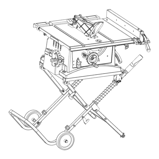
- Page 15 UNPACKING YOUR TABLE ® !!!!
- Page 16 Blade guard fence Miter gauge slot tilting scale indicator Miter gauge Rip fence storage table Miter gauge storage locking lever lock lever Overload reset Blade bevel ON/OFF switch with lock handle safety key Blade elevation and tilting handwheet Blade Riving knife Table insert Anti-kickback pawls...
- Page 17 ANTI-KICKBACK PAWLS - To FREEHAND - Performing a cut without using a rip fence, miter gauge, hold prevent the workpiece being kicked down or other proper device to prevent upward or back toward the front of the the workpiece from twisting during the table saw by the spinning blade.
- Page 18 OVERLOAD RESET SWITCH - SAW BLADE PATH - The area of the Protects the motor if it overloads during workpiece or table top directly in line with the travel of the blade or the part operation, provides a way to restart the of the workpiece that will be cut.
- Page 19 Fig. A=I For your safety, never connect plug to power source receptacle until all assembly and adjustment steps are complete, and you have read and understood the safety instructions. o Stand may pop up unexpectedly without weight of saw on stand. Fig.
- Page 20 SETTING UP THE STAND (Fig. D, E, F) Fig. F 1. Cut the plastic band holding the stand assembly together. Lift up the Saw/Stand assembly into the vertical position as shown. (Fig. D) 2. Release hook (1) securing leg set (2) to frame.
- Page 21 b ) and the. locking.handle (6) to the Fig.N ottom ot the set plate (4). Fig. K Front _._-_--5 Push stick (Fig. I, J) c_-_.._6 Attach the metal push-stick storage bracket (1) into the provided slots (2) Anti-kickback pawls (Fig. L) on the right side of the body shell.
- Page 22 Rivingknife (Fig. M) the cord. Do not wrap the power cord Storage brackets for the riving knife are around the dust port (3). located on the right side of the stand. 1. Remove the washer (8) and the Fig. 0 locking handle (10).
- Page 23 INSTALLING THE REAR TABLE Fig. R EXTENSION (Fig. Q, R) 1. Insert the two tubes (2) into the rear table extension (1). (Fig. Q) NOTE: They must be inserted into the back of the extension with the bent end last so that the bar will hold the extension in place.
- Page 24 2. Remove t hearbornut(2)andouter RIVING KNIFE ASSEMBLY bladeflange (3).(Fig.T) WARNING e To avoid injury from an accidental start, make sure the switch is in the OFF position and the plug is disconnected from the power source outlet. e Never operate this saw without the riving knife in the correct position.
- Page 25 o Never operate this tool without the WARNING riving knife in the correct position. oTo avoid the lock lever interferring o Never operate this tool without the table insert, after tighten the the blade guard in place for all riving knife, position the lock lever through sawing operations.
- Page 26 o Thebladebodymustbethinner t han If the blade is partial to left side: thethickness o fthe riving knifebut 1. Turn the right adjustment screw (3) thebladekerfmustbethicker t han counterclockwise and adjust the left side adjustment screw (2) clockwise. the riving knife. 2.
- Page 27 Place the front of assembly into the 7. Make sure that the assembly is locked back slot on the riving knife and in place both in front and back. push downward. Release the locking knob. Make sure the lock knob is Fig.
- Page 28 AVOIDING KICKBACKS (Fig. CC) Fig. DD (Work thrown back towards you) by keeping the blade sharp, the rip fence parallel to the saw blade and by keeping the riving knife, anti-kickback pawls and guards in place, aligned and functioning. Do not release work before passing it completely beyond the saw blade.
- Page 29 RiP FENCE iNDiCATOR RiP FENCE ADJUSTMENT (Fig. FF) ADJUSTMENT (Fig. GG) 1. The fence (1) is moved by lifting up on the handle (2) and sliding 1. The rip fence indicator (6) points to the fence to the desired location. the measurement scale.
- Page 30 REMOVING THE BLADE (Fig. S, T, U) I,,A WARNING] To avoid injury from an accidental start, make sure the switch is in the OFF position and the plug is disconnected from the power source outlet. 1. Remove the table insert by snapping ADJUSTING THE TABLE iNSERT out from the hole (8).
- Page 31 ADJUSTING THE 90 ° AND 45 ° 45 ° Stop 1. Disconnect the saw from the power POSiTiVE STOPS (Fig. JJ, JJ=l) source. Your saw has positive stops that will 2. Raise the blade to the maximum quickly position the saw blade at 90 ° elevation.
- Page 32 BLADE TiLTiNG SCALE iNDiCATOR 1. Remove the safety switch key and (Fig. KK) unplug the saw. NOTE: This is located on the top of the 2. Remove the blade guard for this table, in front of the blade guard. procedure but reinstall and realign 1.
- Page 33 BASIC SAW OPERATIONS 2. To turn the saw OFF, move the switch downward. RAISE THE BLADE (Fig. MM) 3. To lock the switch in the OFF position, To raise or lower the blade, turn the grasp the end (or yellow part) of the blade elevation handwheel (1) to the safety switch key (1), and pull it out.
- Page 34 USING THE TABLE EXTENSION WARNING I (Fig. 00) Before using the saw each time, 1. Release the extension cam locking check the following: levers (3) in the front and rear table 1. The blade is tightened to the arbor. positions. 2.
- Page 35 1.Remove t hemiter gauge andstore it WARNING] inthe"storage" compartment inthe When width or rip narrower than baseofthesaw. 2 in. the push stick cannot be 2. Secure theripfencetothetable. used because the blade guard will 3. Raise thebladeso itis about1/8in. interfere. Use the auxiliary fence (4) higher t hanthetopoftheworkpiece.
- Page 36 BEVEL RIPPING MAKE A FEATHERBOARD (Fig. RR) Thiscutis thesameas ripping except Select a solid piece of lumber thebladebevel a ngleis settoanangle approximately 3/4 in thick, 4 in wide and otherthan"0 °''. 18 in long. To make a featherboard, one end of the lumber at 60 degrees, RIPPING SMALL PIECES then cut 8 in-long slots 1/4 in apart on the angled end as shown in Fig.
- Page 37 AUXILIARY FENCE (Fig. TT) MAKE A PUSH BLOCK (Fig. UU) Making the base: Making the base: o Start with a piece of 3/8 in. plywood o Start with a 3/8 in. plywood at least at least 5-1/2 in. wide or wider and 5-1/2 in.
- Page 38 I WARNING CROSSCUTTING (Fig. VV) WARNING] Always position the larger surface of the workpiece on the table To prevent serious injury: when crosscutting and/or bevel o Do not allow familiarity or frequent crosscutting to avoid instability. use of your table saw to cause careless mistakes.
- Page 39 BEVEL CROSSCUTTING (Fig. XX) groove because the bevel angle may 0°-45 ° BLADE BEVEL & 90 ° MITER cause the blade guard to interfere with the cut if used on the left side ANGLE This cutting operation is the same as crosscutting except the blade groove.
- Page 40 USING THE WOOD FACING ON THE To avoid the risk of personal RIP FENCE (Fig. as) injury. Always use push block, When performing some special cutting auxiliary fence and featherboard operations, you can add a wood facing when making non4hrough cut.
- Page 41 DADO CUTS (FIG. cc, dd) 6. Use only the correct number of round outside blades and inside i,,_, WARNING] chippers as shown in the dado set's o Only Stackable dado blades can instruction manual. Blade/chippers be used on this saw. must not exceed 1/2 in.
- Page 42 MAINTAINING YOUR TABLE SAW Observe any movement of the motor mounting mechanism. GENERAL MAINTENANCE Loosen or tighten the four hex screws (1) by hex wrench for smooth WARNING operation. Only 1/8 turn at a time. NOTE: Do not adjust the screw For your own safety, turn the switch more than 1/2 turn as this may OFF and remove the switch key.
- Page 43 LUBRiCATiON rip fence, miter gauge and stand assembly to the table saw. All motor bearings are permanently NOTE: To reinstall the same brushes, lubricated at the factory and require no additional lubrication. On all mechanical first make sure the brushes go back in the same sides they came out.
- Page 44 i,A WARNING To avoid injury from accidental starting, always turn switch OFF and unplug the tool before moving, replacing the blade or making adjustments. PROBLEM POSSIBLE CAUSES CORRECTIVE ACTION Saw will not 1. Saw is not plugged in. 1. Plug in saw. start.
- Page 45 1_ WARNING To avoid injury from accidental starting, always turn switch OFF and unplug the tool before moving, replacing the blade or making adjustments. Material kicked 1. Rip fence out of adjustment. 1. Align rip fence with miter back from blade. 2.
- Page 46 PUSH STICK CONSTRUCTION Use good quality plywood or solid wood ® Use 1/2 in. or 3/4 in. material ® Push stick MUST be thinner than the width of ® material being cut Drill Hole For Hanging Notch To Prevent Hand From Slipping Cut Here To Push 1/2 in.
- Page 47 10 IN. JOBSITE TABLE SAW MODEL NO. 137.284630 i WAR.I.Gi When servicing use only CRAFTSMAN replacement parts, Use of any other parts many create HAZARD or cause product damage. Any attempt to repair or replace electrical parts on this Table...
- Page 48 10 iN. JOBSITE TABLE SAW MODEL NO= 137=284630 SCHEMATIC A...
- Page 49 10 iN, JOBSITE TABLE SAW MODEL NO. 137.284630 PARTS LiST FOR MOTOR Size i.D. Description 3089 FIELD ASS'Y OHX9 NEEDLE BEARING OJXS H EX. SOC. SETSCREW MS_J.8-8 OKCN CR. RE. PAN HEAD TAPPING & WA3HERSCREW M5"12'-50 OKTK STRAIN RELIEF OQFE BRUSH COVER OQFF CARBON...
- Page 50 10 IN. JOBSITE TABLE SAW MODEL NO. 137.284630 PARTS LiST FOR STAND Size 5iXe Description Description 0lAD V_NG 2A2R LOCKING CABLETIE O1AE LEVELING 2CFW RUBBER FOOT BUSH OJ4E FLAT W_SH ER q)6'13-1 2CRF HOOK OJ4R FLAT WASHER 2LAL BUSH ¢10"20-3 OJ4W FLAT WASHER 2VE/_...
- Page 51 Congratulations on makL#g a smaftpurchase. Your new Craftsman _' product is designed and manufactured for years of dependable operation. But like all products, it may require repair from time to time. That's when having a Repair Protection Agreement can save you money and aggravation.
- Page 52 Your Home For expeR troubleshooting and home solutions advice: www, managemyhome corn For repair -in your home - of all major brand appliance, lawn and garden equipment, or heating and cooling systems, no matter who made it, no matter who sold it! For the replacement parts, accessories and owner's manuals that you need to do-it-you_elf For Sears professional installation of home appliances...
Need help?
Do you have a question about the 137.284630 and is the answer not in the manual?
Questions and answers