Table of Contents
Advertisement
Operator's Manual
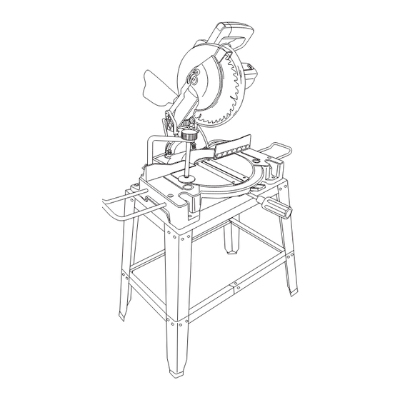
10 in. COMPOUND MITER SAW
WITH STAND AND LASER TRAC
Model No. 137.212410
CAUTION:
Before using this Miter Saw,
read this manual and follow
all its Safety Rules and
Operating Instructions
Customer Help Line
For Technical Support
1-800-843-1682
Sears, Roebuck and Co., Hoffman Estates, IL60179 USA
Visit our Craftsman website: www.sears.com/craftsman
Part No. 13721241001
®
●
●
●
●
●
Sears Parts &
Repair Center
1-800-469-4663
1
Safety Instructions
Installation
Operation
Maintenance
Parts List
Printed in China
Advertisement
Table of Contents

Related Manuals for Craftsman 137.21241


Summary of Contents for Craftsman 137.21241
- Page 1 Safety Rules and Operating Instructions Customer Help Line For Technical Support 1-800-843-1682 Sears, Roebuck and Co., Hoffman Estates, IL60179 USA Visit our Craftsman website: www.sears.com/craftsman Part No. 13721241001 ® ● Safety Instructions ● Installation ●...
-
Page 2: Table Of Contents
Tools Needed for Assembly ... Carton Contents ... CRAFTSMAN ONE YEAR FULL WARRANTY If this Craftsman tool fails due to a defect in material or workmanship within one year from the date of purchase, call 1-800-4-MY-HOME proves impossible). This warranty applies for only 90 days from the date of purchase if this product is ever used for commercial or rental purposes. -
Page 3: Warning Icons
WARNING ICONS Your power tool and its Operator’s Manual may contain “WARNING ICONS” (a picture symbol intended to alert you to, and/or instruct you how to avoid, a potentially hazardous condition). Understanding and heeding these symbols will help you operate your tool better and safer. Shown below are some of the symbols you may see. -
Page 4: Power Tool Safety
GENERAL SAFETY INSTRUCTIONS BEFORE USING THIS POWER TOOL Safety is a combination of common sense, staying alert and knowing how to use your power tool. WARNING To avoid mistakes that could cause serious injury, do not plug the tool in until you have read and understood the following. - Page 5 to determine that it will operate properly and perform its intended function – check for alignment of moving parts, binding of moving parts, breakage of parts, mounting and any other conditions that may affect its operation. A guard or other part that is damaged should be properly repaired or replaced.
-
Page 6: Compound Miter Saw Safety
COMPOUND MITER SAW SAFETY SPECIFIC SAFETY INSTRUCTIONS FOR THIS COMPOUND MITER SAW 1. DO NOT USE THIN KERF BLADES they can deflect and contact guard and can cause possible injury to the operator. 2. DO NOT operate the miter saw until it is completely assembled and installed according to these instructions. -
Page 7: Electrical Requirements And Safety
ELECTRICAL REQUIREMENTS AND SAFETY GROUNDING INSTRUCTIONS IN THE EVENT OF A MALFUNCTION OR BREAKDOWN, grounding provides a path of least resistance for electric currents and reduces the risk of electric shock. This tool is equipped with an electrical cord that has an equipment- grounding conductor and a grounding plug. -
Page 8: Accessories And Attachments
ACCESSORIES AND ATTACHMENTS RECOMMENDED ACCESSORIES WARNING ● Use only accessories recommended for this miter saw. Follow instructions that accompany accessories. Use of improper accessories may cause hazards. ● The use of any cutting tool except 10 in. saw blades which meet the requirements under recommended accessories is prohibited. -
Page 9: Carton Contents
UNPACKING YOUR MITER SAW WARNING To avoid injury from unexpected starting or electrical shock, do not plug the power cord into a source of power during unpacking and assembly. This cord must remain unplugged whenever you are working on the saw. 1. -
Page 10: Know Your Compound Miter Saw
KNOW YOUR COMPOUND MITER SAW Fence Table Table Insert Extension Wing Locking Screw Laser On/Off Switch Hand Hold for Transportation Bevel Lock Handle... -
Page 11: Glossary Of Terms
COMPOUND MITER SAW TERMS ARBOR LOCK – Allows the user to keep the blade from rotating while tightening or loosening the arbor bolt during blade replacement or removal. BASE – Supports the table, holds accessories and allows for workbench or leg set mounting. BEVEL LOCKING HANDLE –... -
Page 12: Assembly And Adjustments
ASSEMBLY AND ADJUSTMENTS ASSEMBLY INSTRUCTIONS WARNING To avoid injury, do not connect this miter saw to the power source until it is completely assembled and adjusted and you have read and understood this Operator’s Manual. ASSEMBLE STAND (FIG. A-1, A-2, A-3) 1. - Page 13 INSTALLING THE MITER HANDLE (FIG. B) 1. Thread the miter handle (1) into the hole (2) located at the front of the miter table. Fig. B WARNING To avoid injury and damage to the saw, transport or store the miter saw with the cutting head locked in the down position.
-
Page 14: Removing Or Installing The Blade
TO INSTALL THE REAR EXTENSION STAY (FIG. F) 1. Loosen the extension stay locking screw (1) under the saw base (2). 2. Place the rear extension stay (3) into the holes provided in the miter saw base. Make sure the angle of stay is in the down position (as shown in Fig. - Page 15 Fig. I 6. Locate the arbor lock (5) on the motor, below the switch handle. (Fig. J) 7. Press the arbor lock, holding it in firmly while turning the blade wrench clockwise. The arbor lock will engage after turning the wrench.
-
Page 16: Adjustment Instructions
ADJUSTMENT INSTRUCTIONS WARNING To avoid injury from an accidental start, make sure the switch is in the OFF position and the plug is not connected to the power source outlet. ADJUSTING FENCE SQUARENESS (FIG. L) 1. Loosen the three fence locking bolts(1). 2. - Page 17 BEVEL STOP ADJUSTMENT (FIG. O, P, Q) WARNING To avoid injury from unexpected starting or electrical shock, make sure the trigger is released and remove the power cord from the power source. 90° Bevel Adjustment (Fig. O) 1. Loosen bevel lock handle (1) and tilt the cutting arm completely to the right.
- Page 18 Mounting instructions 1. For stationary use, place the saw in the desired location, directly on a workbench where there is room for handling and proper support of the workpiece. The base of the saw has four mounting holes. Bolt the base of the miter saw (1) to the work surface (5), using the fastening method as shown in Fig.
-
Page 19: Operation
SAFETY INSTRUCTIONS FOR BASIC SAW OPERATION BEFORE USING THE MITER SAW WARNING To avoid mistakes that could cause serious, permanent injury, do not plug the tool in until the following steps are completed: ● Completely assemble and adjust the saw, following the instructions. - Page 20 PLAN YOUR WORK ● Use the right tool. Don’t force a tool or attachment to do a job it was not designed to do. Use a different tool for any workpiece that can’t be held in a solidly braced, fixed position.
-
Page 21: Before Leaving The Saw
BODY AND HAND POSITION (FIG. U) WARNING Never place hands near the cutting area. Proper positioning of your body and hands when operating the miter saw will make cutting easier and safer. Keep children away. Keep all visitors at a safe distance from the miter saw. Make sure bystanders are clear of the saw and workpiece. - Page 22 MITER CUT (FIG. W) 1. When a miter cut is required, unlock the miter table by turning the miter handle (1) counterclockwise. 2. While holding the miter handle, press down on the positive stop locking lever (2) to disengage the positive stop locking lever. 3.
- Page 23 CUTTING BASE MOLDING (FIG. AA) Base moldings and many other moldings can be cut on a compound miter saw. The setup of the saw depends on molding characteristics and application, as shown. Perform practice cuts on scrap material to achieve best results: 1.
-
Page 24: Maintenance
MAINTENANCE DANGER To avoid injury, never put lubricants on the blade while it is spinning. WARNING To avoid fire or toxic reaction, never use gasoline, naphtha acetone, lacquer thinner or similar highly volatile solvents to clean the miter saw. WARNING To avoid injury from unexpected starting or electrical shock, unplug the power cord before working on the saw. -
Page 25: Troubleshooting Guide
TROUBLESHOOTING GUIDE WARNING To avoid injury from accidental starting, always turn switch OFF and unplug the tool before moving, replacing the blade or making adjustments. TROUBLESHOOTING GUIDE - MOTOR PROBLEM PROBLEM CAUSE Brake does not 1. Motor brushes not sealed or lightly stop the blade sticking. -
Page 26: Parts List
10 in. COMPOUND MITER SAW WARNING When servicing use only CRAFTSMAN replacement parts. Use of any other parts many create a HAZARD or cause product damage. Any attempt to repair or replace electrical parts on this Miter Saw may create a HAZARD unless repair is done by a qualified service technician. Repair service is available at your nearest Sears Service Centre. - Page 27 10 in. COMPOUND MITER SAW SCHEMATIC FOR SAW X3P3 X3P4 X3W2 X3T1 X3T2 X3S0 X3T3 X3T4 X3SF X3ST X3SG X3SH X3SJ X3SV X3PG X3TB X3TG X3R8 X3R9 X3RA X3RB X3WB X3RV X3RH X3RL X3TJ X3RM X3RK X3T8 X3S6 X3S7 X3SM X3S8 X3W4 X3ST X3SG...
- Page 28 10 in. COMPOUND MITER SAW PARTS LIST AND SCHEMATIC FOR MOTOR I.D. Description X3P0 HEX. SOC. HD. CAP SCREW X3PK LABEL X3PL BRUSH HOLDER ASS’Y X3PM BRUSH COVER X3PQ MOTOR HOUSING X3PR BEARING X3PS SPRING X3PT ARMATURE ASS’Y X3PU COMPRESSION SPRING X3PV ARBOR LOCK X3PW BEARING...
- Page 29 10 in. COMPOUND MITER SAW PARTS LIST AND SCHEMATIC FOR STAND I.D. Description X3NM SHORT BOTTOM SUPPORT X3NN FOOT PAD X3NQ LOWER LEG X3NR UPPER LEG X3NS CAPHEAD SQUARE NECK BOLT X3NT SHORT UPPER SUPPORT X3NX FLAT WASHER X3NY HEX. HD. BOLT X3SV LONG BOTTOM SUPPORT BRACKET X3SW...
-
Page 30: Repair Protection Agreements
REPAIR PROTECTION AGREEMENTS Congratulations on making a smart purchase. Your new Craftsman manufactured for years of dependable operation. But like all products, it may require repair from time to time. That’s when having a Repair Protection Agreement can save you money and aggravation. - Page 31 Get it fixed, at your home or ours! For expert troubleshooting and home solutions advice: For repair – in your home – of all major brand appliances, lawn and garden equipment, or heating and cooling systems, no matter who made it, no matter who sold it! For the r eplacement parts, accessories and owner’s manuals that you need to do-it-yourself.
Need help?
Do you have a question about the 137.21241 and is the answer not in the manual?
Questions and answers