Table of Contents
Advertisement
Operator's Manual
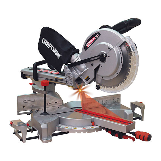
12 in. SLIDING COMPOUND
MITER SAW WITH LASER TRAC
Model No. 137.212390
CAUTION:
Before using this Miter Saw,
read this manual and follow
all its Safety Rules and
Operating Instructions
Customer Help Line
For Technical Support
1-800-843-1682
Sears, Roebuck and Co., Hoffman Estates, lL 60179 USA
Visit our Craftsman website: www.sears.com/craftsman
Part No. 137212390001
®
Safety Instructions
Installation
Operation
Maintenance
Parts List
Sears Parts &
Repair Center
1-800-488-1222
1
Printed in China
Advertisement
Table of Contents

Related Manuals for Craftsman 137.21239


Summary of Contents for Craftsman 137.21239
- Page 1 Safety Rules and Operating Instructions Customer Help Line For Technical Support 1-800-843-1682 Sears, Roebuck and Co., Hoffman Estates, lL 60179 USA Visit our Craftsman website: www.sears.com/craftsman Part No. 137212390001 ® Safety Instructions Installation Operation Maintenance Parts List Sears Parts &...
-
Page 2: Table Of Contents
Compound Miter Saw Safety ... Electrical Requirements and Safety ... Accessories and Attachments ... Tools Needed for Assembly ... Carton Contents ... Know Your Compound Miter Saw ... Glossary of Terms ... Assembly and Adjustments ... Operation ... Maintenance ... -
Page 3: Warranty
CRAFTSMAN ONE YEAR FULL WARRANTY If this Craftsman tool fails due to a defect in material or workmanship within one year from the date of purchase, call 1-800-4-MY-HOME free repair (or replacement if repair proves impossible). This warranty applies for only 90 days from the date of purchase if this product is ever used for commercial or rental purposes. -
Page 4: Warning Icons
WARNING ICONS Your power tool and its Owner’s Manual may contain “WARNING ICONS” (a picture symbol intended to alert you to, and/or instruct you how to avoid, a potentially hazardous condition). Understanding and heeding these symbols will help you operate your tool better and safer. Shown below are some of the symbols you may see. -
Page 5: Power Tool Safety
POWER TOOL SAFETY GENERAL SAFETY INSTRUCTIONS BEFORE USING THIS POWER TOOL Safety is a combination of common sense, staying alert and knowing how to use your power tool. CAUTION To avoid mistakes that could cause serious injury, do not plug the tool in until you have read and understood the following. - Page 6 POWER TOOL SAFETY 12.ALWAYS WEAR EYE PROTECTION. Any power tool can throw foreign objects into the eyes and could cause permanent eye damage. ALWAYS wear Safety Goggles (not glasses) that comply with ANSI Safety standard Z87.1. Everyday eyeglasses have only impact–resistant lenses.
-
Page 7: Maintain Tools With Care
Follow instructions for lubricating and changing accessories. 23. WARNING: Dust generated from certain materials can be hazardous to your health. Always operate saw in well-ventilated area and provide for proper dust removal. DANGER with electronic devices, such as... -
Page 8: Compound Miter Saw Safety
4. KEEP HANDS out of the path of the saw blade. If the workpiece you are cutting would cause your hands to be within 8-3/4 in. of the saw blade, the workpiece should be clamped in place before making the cut. -
Page 9: Power Supply And Motor Specifications
fi ngers to be within 8-3/4 in. of the saw blade the workpiece is too small. 22.PROVIDE adequate support to the sides of the saw table for long work pieces. 23.NEVER use the miter saw in an area with fl ammable liquids or gases. -
Page 10: Electrical Requirements And Safety
1. Connect this saw to a 120 V circuit. This circuit must not be less than a #12 wire with a 20 A time lag fuse or a #14 wire with a 15 A time lag fuse. -
Page 11: Guidelines For Extension Cords
For heavy loads, the voltage at motor terminals must equal the voltage specifi ed on the nameplate. c. IMPROPER or dull saw blades are used. 5. Most motor troubles may be traced to loose or incorrect connections, overload, low voltage or inadequate power supply wiring. -
Page 12: Accessories And Attachments
Sears. WARNING Read warnings and conditions on your CARBIDE TIPPED SAW BLADE. Do not operate the saw without the proper saw blade guard in place. Carbide is a very hard but brittle material. Care should be taken while mounting, using, and storing carbide tipped blades to prevent accidental damage. -
Page 13: Tools Needed For Assembly
TOOLS NEEDED FOR ASSEMBLY Not supplied Supplied Adjustable Wrench Blade Wrench Hex Key Combination Square Phillips Screwdriver Slotted Screwdriver COMBINATION SQUARE MUST BE TRUE Should not gap or overlap when square is fl ipped over (see dotted fi gure). Straight edge or a 3/4 in. Draw light line board, this edge must be on board along... -
Page 14: Carton Contents
WARNING If any part is missing or damaged, do not attempt to assemble the miter saw, or plug in the power cord until the missing or damaged part is correctly replaced. To avoid electric shock, use only identical replacement parts when servicing double insulated tools. -
Page 15: Know Your Compound Miter Saw
KNOW YOUR SLIDING MITER SAW Dust Bag Carrying Handle Bevel Detent Pin Hold-down Clamp Sliding Fence Left Table Extension Carrying Handle Laser ON/OFF Switch ON/OFF Trigger Switch Base Table Positive Stop Locking Lever Mounting Hole Stop Latch Knob Motor Positive Miter Detents... -
Page 16: Glossary Of Terms
MITER HANDLE – Used to rotate the table, and to rotate the saw to a right or left cutting position. MITER SCALE – Measures the miter angle 0° to 45° left and right. - Page 17 GLOSSARY OF TERMS POSITIVE STOP LOCKING LEVER – Locks the miter saw at a preset positive stop for the desired miter angle. SWITCH HANDLE – The switch handle contains the trigger switch and safety lock-off button. The blade is lowered into the workpiece by pushing down on the handle.
-
Page 18: Assembly And Adjustments
Estimated Assembly Time: 5 – 10 minutes WARNING To avoid injury, do not connect this miter saw to the power source until it is completely assembled and adjusted and you have read and understood this Operator’s Manual. INSTALLING THE MITER HANDLE (FIG. - Page 19 2. Push the stop latch knob (2) into the locking hole. IMPORTANT: To avoid damage, never carry the miter saw by the switch handle, the cutting arm or the miter handle. ALWAYS use the designated carrying handles located on the top of the machine and in the back of the unit.
- Page 20 ● Lock the slide carriage in place by tightening the slide carriage lock knob. ● To avoid back injury, lift the saw by using the designated carrying handles located on the top of the machine. When lifting, bend at your knees, not from your back.
-
Page 21: Removing Or Installing The Blade
● Only use a 12-inch diameter blade. 1. Unplug the saw from the outlet 2. Raise the miter saw to the upright position. 3. Raise the lower clear plastic blade guard (1) to the uppermost position. - Page 22 Also, the 12 in. blade has a 1 in. arbor hole with a 5/8 in. reducer (8) to mount onto the saw. Fig. M INSTALLING BLADE (FIG. K, L, M)
- Page 23 Class II laser beam. The laser beam will enable to preview the saw blade path on the stock to be cut before starting the miter saw. This laser guide is powered by the transformed alternating current supply directly through the power lead.
-
Page 24: Bevel Stop Adjustment
2. Place a combination square (2) on the miter table with the ruler against the table and the heel of the square against the saw blade. 3. If the blade is not 90 with the miter table (5), loosen the... - Page 25 The sliding compound miter saw scale can be easily read, showing miter angles from 0° to 45° to the left, and 0° to 45° to the right. The miter saw table has nine of the most common angle setttings with positive stops at 0°, 15°, 22.5°, 31.6°, and 45°.
- Page 26 4. Adjust the fence 90° to the blade and tighten the four fence locking bolts. CAUTION: If the saw has not been used recently, recheck blade squareness to the fence and readjust if needed. 5. After fence has been aligned, using...
- Page 27 SLIDING THE REAR EXTENSION SUPPORT BAR (FIG. T) WARNING To avoid possible personal injury or damage to the miter saw due to tipping, do not operate the saw without the Rear Extension Support Bar. Loosen the two screws (1) and extend...
-
Page 28: Operation
● Replace bent, damaged, missing or defective parts before using the saw again. - Page 29 fl ammable liquids, vapors, or gases. OPERATION ● Plan ahead to protect your eyes, hands, face and ears. ● Know your miter saw. Read and understand the Operator’s Manual and labels affi xed to the tool. Learn its application and limitations as well as the specifi...
-
Page 30: Dress For Safety
● Never use another person as a substitute for a table extension, or as an additional support for a workpiece that is longer or wider than the basic miter saw table, or to help feed, support, or pull the workpiece. - Page 31 ● Do not use this saw to cut small pieces. If the workpiece being cut would cause your hand or fi ngers to be within 8-3/4 inches of the saw blade the workpiece is too small. Keep hands and fi ngers out of the “no hands zone”...
-
Page 32: Basic Saw Operations
● Hold workpiece fi rmly against the fence to prevent movement toward the blade. ● With the power switch OFF, bring the saw blade down to the workpiece to see the cutting path of the blade. ● Press in lock-off switch in trigger switch handle. -
Page 33: Sliding Carriage System
The miter saw is equipped with an automatic blade brake. When the trigger switch is released, the electric blade brake will stop the blade within approximately 10 seconds. Fig. V SLIDING FENCE & REMOVE SLIDING FENCE (FIG. W) Sliding Fence... -
Page 34: Before Leaving The Saw
At extreme miter or bevel angles the saw blade may also contact the fence. BEVEL CUT (FIG. Z) 1. When a bevel cut is required, loosen the bevel lock handle (1) by turning it clockwise. - Page 35 Fig. Z NOTE: The saw comes with a 33.9° crown molding stop. 33.9° BEVEL STOP FOR CROWN MOLDING (FIG. AA) 1. Push the bevel detent stop pin (2) in toward the front of the machine. 2. Loosen the bevel lock handle (1).
- Page 36 4. Grasp the switch handle (2) and pull the carriage (3) forward until the center of the saw blade is over the front of the workpiece (4). 5. Engage the trigger to turn the saw 6. When the saw reaches full speed,...
- Page 37 When making multiple or repetitive cuts that result in cut-off pieces of one inch or less, it is possible for the saw blade to catch the cut-off piece and throw it out of the saw or into the blade guard and housing, possibly causing damage or injury.
-
Page 38: Cutting Crown Molding
In order to accurately cut crown molding for a 90° inside or outside corner, lay the molding with its broad back surface fl at on the saw table. When setting the bevel and miter angles for compound miters, remember that the settings are interdependent;... -
Page 39: Crown Molding Chart
CROWN MOLDING CHART Compound Miter saw Miter and bevel Angle settings Wall to Crown Molding Angle 52/38° Crown Molding Angle Miter Bevel Between Setting Setting Walls 42.93 41.08 42.39 40.79 41.85 40.50 41.32 40.20 40.79 39.90 40.28 39.61 39.76 39.30 39.25... -
Page 40: Maintenance
● To avoid injury from unexpected starting or electrical shock, unplug the power cord before working on the saw. ● For your safety, this saw is double insulated. To avoid electrical shock, fi re or injury, use only parts identical to those identifi ed in the parts list. - Page 41 SAWDUST Periodically, sawdust will accumulate under the worktable and base. This could cause diffi culty in the movement of the worktable when setting up a miter cut. Frequently blow out or vacuum up the sawdust. WARNING If blowing sawdust, wear proper eye protection to keep debris from blowing into eyes.
-
Page 42: Troubleshooting Guide
TROUBLESHOOTING GUIDE WARNING To avoid injury from accidental starting, always turn switch OFF and unplug the tool before moving, replacing the blade or making adjustments. TROUBLESHOOTING GUIDE - MOTOR PROBLEM PROBLEM CAUSE Brake does 1. Motor brushes not sealed not stop blade or lightly sticking. - Page 43 2. Dull or warped blade. wood. 3. Improper blade size. 4 Wood is moving during cut. Saw vibrates 1. Saw blade not round / or shakes. damaged / loose. 2. Arbor bolt loose. SUGGESTED CORRECTIVE ACTION 1. See ADJUSTMENT - Setting Cutting Depth section.
-
Page 44: Parts List
12 in. COMPOUND MITER SAW WARNING When servicing use only CRAFTSMAN replacement parts. Use of any other parts many create a HAZARD or cause product damage. Any attempt to repair or replace electrical parts on this Miter Saw may create a HAZARD unless repair is done by a qualifi ed service technician. Repair service is available at your nearest Sears Service Center. - Page 45 12 in. COMPOUND MITER SAW MODEL NO. 137.212390 SCHEMATIC A...
- Page 46 12 in. COMPOUND MITER SAW PARTS LIST FOR SAW SCHEMATIC B I.D. Description 0DTH CENTER BOLT 0H9A REAR EXTENTION STAY 0J6A FLAT WASHER 0J74 FLAT WASHER 0JAZ WAVE WASHER 0JPF HEX. HD. BOLT 0JXB HEX. SOC. SET SCREW 0JXG HEX. SOC. SET SCREW 0K2B HEX.
- Page 47 12 in. COMPOUND MITER SAW MODEL NO. 137.212390 SCHEMATIC B...
- Page 48 12 in. COMPOUND MITER SAW PARTS LIST FOR MOTOR I.D. Description 0JCF SPRING PIN 0JX2 HEX. SOC SET SCREW 0K44 CR. RE. PAN HD. SCREW & WASHER 0KCP CR. RE. PAN HEAD TAPPING & WASHER SCREW 0KLA PLASTIC SCREW 0Q9K...
- Page 49 NOTE...
- Page 50 Get it fixed, at your home or ours! For expert troubleshooting and home solutions advice: For repair – in your home – of all major brand appliances, lawn and garden equipment, or heating and cooling systems, no matter who made it, no matter who sold it! For the replacement parts, accessories and owner’s manuals that you need to do-it-yourself.
Need help?
Do you have a question about the 137.21239 and is the answer not in the manual?
Questions and answers
I need the saftey guard for the blade on a 12" sliding compound miter saw craftsman model ****.212390. Where can I find one??
The lower blade guard is attached to the saw for protection. If the lower guard is damaged, it must be replaced before using the saw. Use only parts identical to those in the parts list. Replacement parts, including the safety guard, can be obtained from a Sears Service Center.
This answer is automatically generated