Advertisement
Quick Links
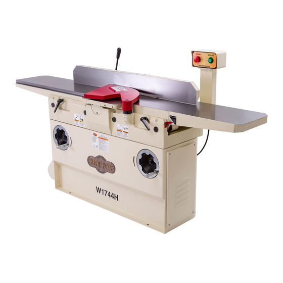
Model W1744H
12" HD Jointer w/Adjustable
Beds & Helical Cutterhead
Manual Insert
Phone #: (360) 734-3482 • Tech Support: techsupport@woodstockint.com • Web: www.woodstockint.com
The Model W1744H is the same as the Model W1744, except it has a helical cutterhead. Besides
differences noted in this insert, the content in the Model W1744 owner's manual is the same for both
machines. Before operating your new machine, you MUST read and understand this insert and the entire
Model W1744 manual to reduce the risk of injury from improper use or setup.
If you have any further questions about this manual insert or the differences between the
Model W1744H and the Model W1744, contact our Technical Support at (360) 734-3482 or email
techsupport@woodstockint.com.
COPYRIGHT © MARCH, 2020 BY WOODSTOCK INTERNATIONAL, INC.
WARNING: NO PORTION OF THIS PUBLICATION MAY BE REPRODUCED IN ANY SHAPE OR FORM WITHOUT
THE WRITTEN APPROVAL OF WOODSTOCK INTERNATIONAL, INC.
#20924CS
Printed in China
Advertisement

Subscribe to Our Youtube Channel
Related Manuals for Woodstock SHOP FOX W1744H


Summary of Contents for Woodstock SHOP FOX W1744H
- Page 1 Model W1744H and the Model W1744, contact our Technical Support at (360) 734-3482 or email techsupport@woodstockint.com. COPYRIGHT © MARCH, 2020 BY WOODSTOCK INTERNATIONAL, INC. WARNING: NO PORTION OF THIS PUBLICATION MAY BE REPRODUCED IN ANY SHAPE OR FORM WITHOUT THE WRITTEN APPROVAL OF WOODSTOCK INTERNATIONAL, INC.
- Page 2 Model W1744H (For Machines Mfd. Since 01/20) MODEL W1744H 12" HEAVYDUTY JOINTER WITH ADJUSTABLE BEDS AND HELICAL CUTTERHEAD Product Dimensions Weight......................884 lbs. Width (side‐to‐side) x Depth (front‐to‐back) x Height........84 x 33 x 43‐1/2 in. Footprint (Length x Width)................. 44‐1/2 x 18 in. Shipping Dimensions Type.......................
- Page 3 Model W1744H (For Machines Mfd. Since 01/20) Fence Information Fence Length..................46‐3/4 in. Fence Width................... 1‐1/2 in. Fence Height..................5‐3/8 in. Fence Stops.................. 45, 90, 135 deg. Cutterhead Information Cutterhead Type..................Helical Cutterhead Diameter................3‐7/8 in. Number of Cutter Rows..................8 Number of Indexable Cutters................
- Page 4 Model W1744H (For Machines Mfd. Since 01/20) SAFETY SAFETY For Your Own Safety, Read Manual Before Operating Machine The purpose of safety symbols is to attract your attention to possible hazardous conditions. This manual uses a series of symbols and signal words intended to convey the level of importance of the safety messages.
- Page 5 INTENDED USAGE. Only use machine for its keep machine in good working condition. A intended purpose—never make modifications machine that is improperly maintained could without prior approval from Woodstock malfunction, leading to serious personal injury International. Modifying machine or using or death.
- Page 6 Model W1744H (For Machines Mfd. Since 01/20) Additional Safety for Jointers Serious cuts, amputation, entanglement, or death can occur from contact with rotating cutterhead or other moving components! Flying chips from cutting operations can cause eye injuries or blindness. Workpieces or inserts/knives thrown by cutterhead (kickback) can strike nearby operator or bystanders with deadly force.
- Page 7 Model W1744H (For Machines Mfd. Since 01/20) ELECTRICAL Circuit Requirements This machine must be connected to the correct size and The machine must be properly set up type of power supply circuit, or fire or electrical damage before it is safe to operate. DO NOT may occur.
- Page 8 Model W1744H (For Machines Mfd. Since 01/20) Grounding Requirements This machine MUST be grounded. In the event of certain The machine must be properly set up types of malfunctions or breakdowns, grounding provides before it is safe to operate. DO NOT a path of least resistance for electric current to travel—in connect this machine to the power order to reduce the risk of electric shock.
- Page 9 Model W1744H (For Machines Mfd. Since 01/20) SETUP Inventory The following is a list of items shipped with your machine. Before beginning setup, lay these items out and inventory them. Note: If you cannot find an item on this list, carefully check around/inside the machine and packaging materials.
- Page 10 Model W1744H (For Machines Mfd. Since 01/20) Installing Cutterhead Mounting Hole Guard (Hidden) The cutterhead guard must be installed for all operations. To install cutterhead guard, do these steps: Set Screw 1. Insert cutterhead guard shaft into mounting hole, as (1 of 2) shown in Figure 3.
- Page 11 Model W1744H (For Machines Mfd. Since 01/20) SERVICE Rotating/Replacing Cutterhead Inserts reduce risk shock accidental startup, always disconnect machine from power before adjustments, maintenance, or service. The helical cutterhead is equipped with 4-sided indexable carbide inserts. Each insert can be removed, rotated, and re-installed to use any one of its four cutting edges.
- Page 12 Model W1744H (For Machines Mfd. Since 01/20) 5. Carefully clean away all sawdust/debris from insert, Torx screw, and surrounding area. Torx Screw 6. Remove Torx screw and insert (see Figure 5), then carefully clean away all dust and debris from insert and insert pocket in cutterhead.
- Page 13 Model W1744H (For Machines Mfd. Since 01/20) Electrical Safety Instructions These pages are current at the time of printing. However, in the spirit of improvement, we may make changes to the electrical systems of future machines. Compare the manufacture date of your machine to the one stated in this manual, and study this section carefully.
- Page 14 Model W1744H (For Machines Mfd. Since 01/20) Wiring Diagram Ground SHOCK HAZARD! Disconnect power before servicing electrical parts. Touching electrified parts 230 VAC will result in severe burns, Read electrocution, or death. Page 14 STOP 6-20 PLUG Before Wiring CONTROL Ground PANEL 13no...
- Page 15 Model W1744H (For Machines Mfd. Since 01/20) Electrical Components Contactor Switch STOP Switch Relay Figure 7. Control panel wiring. Figure 9. Magnetic switch assembly wiring. Start Capacitor Run Capacitor Figure 8. Motor capacitors. -15-...
- Page 16 Model W1744H (For Machines Mfd. Since 01/20) PARTS Base 142-1 142-2 -16-...
- Page 17 Model W1744H (For Machines Mfd. Since 01/20) Base Parts List PART # DESCRIPTION REF PART # DESCRIPTION X1744H101 CUTTERHEAD GUARD X1744H143 STOP BLOCK X1744H104 FLAT HD SCR M8-1.25 X 16 X1744H144 INT RETAINING RING 35MM X1744H105 CUTTERHEAD GUARD FLAT WASHER X1744H145 SHAFT X1744H106...
- Page 18 Model W1744H (For Machines Mfd. Since 01/20) Tables REF PART # DESCRIPTION REF PART # DESCRIPTION X1744H201 TABLE (LEFT) X1744H211 CAP SCREW M10-1.5 X 30 X1744H202 TABLE LIP (LEFT) X1744H212 LOCK WASHER 10MM X1744H203 LOCK WASHER 10MM X1744H213 DEPTH SCALE X1744H204 CAP SCREW M10-1.5 X 35 X1744H214...
- Page 19 Model W1744H (For Machines Mfd. Since 01/20) Fence REF PART # DESCRIPTION REF PART # DESCRIPTION X1744H301 FENCE BRACKET X1744H324 FENCE BRACKET HEX NUT M12-1.75 X1744H302 FLAT WASHER 12MM X1744H325 LEFT BRACKET X1744H303 LOCK WASHER 12MM X1744H326 X1744H304 CAP SCREW M12-1.75 X 30 X1744H327 HANDLE X1744H305...
- Page 20 Model W1744H (For Machines Mfd. Since 01/20) Stand 415-5 415-2 415-8 415-3 415-6 415-9 415-7 415-10 415-4 401-1 401-2 415-1 401-1 401-2 435 434 434-1 434-3 434-5 434-2 434-4 -20-...
- Page 21 Model W1744H (For Machines Mfd. Since 01/20) Stand Parts List PART # DESCRIPTION PART # DESCRIPTION X1744H401 VENTED COVER X1744H424 CABINET HEX NUT M6 401-1 X1744H401-1 BUTTON HD CAP SCR M6-1 X 20 X1744H425 FLAT WASHER 6MM 401-2 X1744H401-2 FLAT WASHER 6MM X1744H426 ADAPTOR X1744H402...
- Page 22 MUST maintain the original location and readability of all labels on this machine. If any label is removed or becomes unreadable, REPLACE that label before allowing the machine to enter service again. Contact Woodstock International, Inc. at (360) 734-3482 or www. shopfoxtools.com to order new labels.
- Page 23 Woodstock International, Inc. will repair, replace, or arrange for a dealer refund, at its expense and option, the Shop Fox machine or machine part proven to be defective for its designed and intended...
- Page 25 457V2 X1742074V2 POWER CORD 12G 3W 72" 6-20P COPYRIGHT © AUGUST, 2012 BY WOODSTOCK INTERNATIONAL, INC. WARNING: NO PORTION OF THIS MANUAL MAY BE REPRODUCED IN ANY SHAPE OR FORM WITHOUT THE WRITTEN APPROVAL OF WOODSTOCK INTERNATIONAL, INC. #15235BLTS Printed in China...
- Page 26 Model W1744/W1744S (Mfg. Since 7/12) SAFETY SAFETY For Your Own Safety, Read Manual Before Operating Machine The purpose of safety symbols is to attract your attention to possible hazardous conditions. This manual uses a series of symbols and signal words intended to convey the level of importance of the safety messages.
- Page 27 INTENDED USAGE. Only use machine for keep machine in good working condition. A its intended purpose and never make machine that is improperly maintained could modifications not approved by Woodstock. malfunction, leading to serious personal injury Modifying machine or using it differently or death.
- Page 28 Model W1744/W1744S (Mfg. Since 7/12) Additional Safety for Jointers JOINTER INJURY RISKS. Familiarize yourself with INSPECTING STOCK. To reduce the risk of the main injury risks associated with jointers— kickback injuries or machine damage, always use common sense and good judgement thoroughly inspect and prepare the workpiece to reduce your risk of injury.
- Page 29 Model W1744/W1744S (Mfg. Since 7/12) ELECTRICAL Circuit Requirements This machine must be connected to the correct size and type of power supply circuit, or fire or electrical damage may occur. Read through this section to determine if an adequate power supply circuit is available. If a correct circuit is not available, a qualified electrician MUST install one before you can connect the machine to power.
- Page 30 Model W1744/W1744S (Mfg. Since 7/12) Grounding Requirements This machine MUST be grounded. In the event of certain types of malfunctions or breakdowns, grounding provides a path of least resistance for electric current to travel—in order to reduce the risk of electric shock. Improper connection of the equipment-grounding wire will increase the risk of electric shock.
- Page 31 Model W1744/W1744S (Mfg. Since 7/12) Wiring Diagram 230 VAC 6-20 PLUG CONTROL Ground PANEL 13no (from behind) Contactor 14no Thermal Overload Ground MAGNETIC SWITCH ASSEMBLY Start Capacitor Ground 200MFD 250VAC 230V Capacitor 20MFD MOTOR 400VAC...
- Page 91 High Quality Machines and Tools Woodstock International, Inc. carries thousands of products designed to meet the needs of today's woodworkers and metalworkers. Ask your dealer about these fine products:...
Need help?
Do you have a question about the SHOP FOX W1744H and is the answer not in the manual?
Questions and answers