Table of Contents
Advertisement
Quick Links
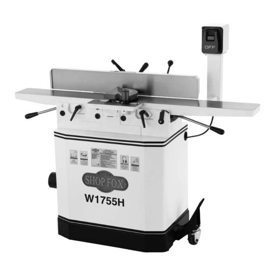
Model W1755H
6" Parallelogram Jointer
w/Helical Cutterhead
Manual Insert
Phone #: (360) 734-3482 • Tech Support: techsupport@woodstockint.com • Web: www.woodstockint.com
The Model W1755H is the same as the Model W1755, except it has a helical cutterhead. Besides
differences noted in this insert, the content in the Model W1755 owner's manual is the same for both
machines. Before operating your new machine, you MUST read and understand this insert and the entire
Model W1755 manual to reduce the risk of injury from improper use or setup.
If you have any further questions about this manual insert or the differences between the
Model W1755H and the Model W1755, contact our Technical Support at (360) 734-3482 or email
techsupport@woodstockint.com.
COPYRIGHT © APRIL, 2020 BY WOODSTOCK INTERNATIONAL, INC.
WARNING: NO PORTION OF THIS PUBLICATION MAY BE REPRODUCED IN ANY SHAPE OR FORM WITHOUT
THE WRITTEN APPROVAL OF WOODSTOCK INTERNATIONAL, INC.
#20927CS
Printed in China
Advertisement
Table of Contents

Subscribe to Our Youtube Channel
Related Manuals for Woodstock Shop Fox W1755H


Summary of Contents for Woodstock Shop Fox W1755H
- Page 1 Model W1755H and the Model W1755, contact our Technical Support at (360) 734-3482 or email techsupport@woodstockint.com. COPYRIGHT © APRIL, 2020 BY WOODSTOCK INTERNATIONAL, INC. WARNING: NO PORTION OF THIS PUBLICATION MAY BE REPRODUCED IN ANY SHAPE OR FORM WITHOUT THE WRITTEN APPROVAL OF WOODSTOCK INTERNATIONAL, INC.
- Page 2 Model W1744H (For Machines Mfd. Since 01/20) MODEL W1755H 6" PARALLELOGRAM JOINTER WITH HELICAL CUTTERHEAD Product Dimensions Weight......................325 lbs. Width (side‐to‐side) x Depth (front‐to‐back) x Height......55‐1/2 x 24‐1/2 x 48 in. Footprint (Length x Width)................. 27 x 20‐1/2 in. Shipping Dimensions Carton #1 Type.....................
- Page 3 Model W1744H (For Machines Mfd. Since 01/20) Main Specifications Main Specifications Bevel Jointing................. 0 – 45 deg. L/R Maximum Width of Cut................... 6 in. Maximum Depth of Cut................1/8 in. Minimum Workpiece Length................8 in. Minimum Workpiece Thickness............... 1/2 in. Number of Cuts Per Minute................
- Page 4 Model W1744H (For Machines Mfd. Since 01/20) Other Country of Origin ....................China Warranty ....................... 2 Years Approximate Assembly & Setup Time ..............1 Hour Serial Number Location ..................ID Label Certified by a Nationally Recognized Testing Laboratory (NRTL) ......... Yes Features Helical Cutterhead with 30 Indexable Carbide Inserts Built‐In Mobile Base...
- Page 5 Model W1755H (For Machines Mfd. Since 01/20) SAFETY SAFETY For Your Own Safety, Read Manual Before Operating Machine The purpose of safety symbols is to attract your attention to possible hazardous conditions. This manual uses a series of symbols and signal words intended to convey the level of importance of the safety messages.
- Page 6 INTENDED USAGE. Only use machine for its keep machine in good working condition. A intended purpose—never make modifications machine that is improperly maintained could without prior approval from Woodstock malfunction, leading to serious personal injury International. Modifying machine or using or death.
- Page 7 Model W1755H (For Machines Mfd. Since 01/20) Additional Safety for Jointers Serious cuts, amputation, entanglement, or death can occur from contact with rotating cutterhead or other moving components! Flying chips from cutting operations can cause eye injuries or blindness. Workpieces or inserts/knives thrown by cutterhead (kickback) can strike nearby operator or bystanders with deadly force.
- Page 8 Model W1755H (For Machines Mfd. Since 01/20) ELECTRICAL Circuit Requirements This machine must be connected to the correct size and The machine must be properly set up type of power supply circuit, or fire or electrical damage before it is safe to operate. DO NOT may occur.
- Page 9 Model W1755H (For Machines Mfd. Since 01/20) Grounding Requirements This machine MUST be grounded. In the event of certain The machine must be properly set up types of malfunctions or breakdowns, grounding provides before it is safe to operate. DO NOT a path of least resistance for electric current to travel—in connect this machine to the power order to reduce the risk of electric shock.
- Page 10 (as recommended) Capacitor 40MFD 250VAC Model W1755H (For Machines Mfd. Since 01/20) Start Capacitor Voltage Conversion 300MFD 125VAC The voltage conversion MUST be performed by an SWITCH electrician or qualified service personnel. (viewed from behind) Remove The voltage conversion procedure consists of rewiring the motor and installing the correct plug.
- Page 11 Model W1755H (For Machines Mfd. Since 01/20) SET UP Inventory If you cannot find an item on this list, The following is a list of items shipped with your machine. carefully check around/inside machine Before beginning setup, lay these items out and inventory and packaging materials.
- Page 12 Model W1755H (For Machines Mfd. Since 01/20) SERVICE Rotating/Replacing Cutterhead Inserts reduce risk shock accidental startup, always disconnect machine from power before adjustments, maintenance, or service. The helical cutterhead is equipped with 4-sided indexable carbide inserts. Each insert can be removed, rotated, and re-installed to use any one of its four cutting edges.
- Page 13 Model W1755H (For Machines Mfd. Since 01/20) 5. Carefully clean away all sawdust/debris from insert, Torx screw, and surrounding area (see Figure 6). Torx Screw 6. Remove Torx screw and insert (see Figure 6), then carefully clean away all dust and debris from insert and pocket.
- Page 14 Model W1755H (For Machines Mfd. Since 01/20) Electrical Safety Instructions These pages are current at the time of printing. However, in the spirit of improvement, we may make changes to the electrical systems of future machines. Compare the manufacture date of your machine to the one stated in this manual, and study this section carefully.
- Page 15 Model W1755H (For Machines Mfd. Since 01/20) Wiring Diagram WARNING! SHOCK HAZARD! Disconnect power before working on wiring. Ground Neutral (Rewired for 240V) Read Page 14 STOP Before Ground 240 VAC Wiring 120 VAC 6-15 Plug 5-15 Plug (as recommended) SWITCH (viewed from behind) Ground...
- Page 16 Model W1755H (For Machines Mfd. Since 01/20) Electrical Components Figure 8. Start/stop switch. Figure 10. Motor junction box. Figure 9. Start capacitor. Figure 11. Run capacitor. -16-...
- Page 17 Model W1755H (For Machines Mfd. Since 01/20) PARTS Stand 28-1 28-8 28-3 28-2 28-4 28-9 28-7 28-5 28-10 28-11 28-6 -17-...
- Page 18 Model W1755H (For Machines Mfd. Since 01/20) Stand Parts List PART # DESCRIPTION PART # DESCRIPTION X1755H001 FLAT WASHER 5MM 28-6 X1755H028-6 R CAPACITOR 40M 250V X1755H002 PANEL 28-7 X1755H028-7 MOTOR JUNCTION BOX X1755H003 FLANGE SCREW M6-1 X 12 28-8 X1755H028-8 CENTRIFUGAL SWITCH 5/8-3450 X1755H004...
- Page 19 Model W1755H (For Machines Mfd. Since 01/20) Jointer -19-...
- Page 20 Model W1755H (For Machines Mfd. Since 01/20) Jointer Parts List PART # DESCRIPTION PART # DESCRIPTION X1755H101 LEVER KNOB X1755H157 LOCK WASHER 8MM X1755H102 SHOULDER STUD X1755H158 BEARING BLOCK (LH) X1755H103 BUSHING X1755H159 BALL BEARING 6004ZZ X1755H104 SHAFT X1755H161 DRIVER BIT TORX T20 X1755H105 SET SCREW M6-1 X 16 X1755H162...
- Page 21 Model W1755H (For Machines Mfd. Since 01/20) Jointer Parts List (Cont.) PART # DESCRIPTION PART # DESCRIPTION X1755H215 CAP SCREW M8-1.25 X 40 X1755H229 SWITCH PEDESTAL X1755H216 CLAMP PLATE X1755H230 CAP SCREW M8-1.25 X 25 X1755H217 MEDIUM ADJUSTMENT SCR X1755H231 LOCK WASHER 8MM X1755H218 PUSH BLOCK...
- Page 22 17. Always feed workpiece against cutterhead rotation. Never move workpiece backward while feeding. 18. Prevent unauthorized use by children or untrained users; restrict access or 208624 disable machine when unattended. Mfd. for Woodstock in China REF PART # DESCRIPTION REF PART # DESCRIPTION...
- Page 23 Woodstock International, Inc. will repair, replace, or arrange for a dealer refund, at its expense and option, the Shop Fox machine or machine part proven to be defective for its designed and intended...
- Page 25 309V2 X1755S309V2 MACHINE ID LABEL CSA V2.07.12 (W1755S) 28-7 X1755028-7 MOTOR JUNCTION BOX COPYRIGHT © AUGUST, 2012 BY WOODSTOCK INTERNATIONAL, INC. WARNING: NO PORTION OF THIS MANUAL MAY BE REPRODUCED IN ANY SHAPE OR FORM WITHOUT THE WRITTEN APPROVAL OF WOODSTOCK INTERNATIONAL, INC.
- Page 26 Model W1755/W1755S (Mfg. Since 7/12) SAFETY SAFETY For Your Own Safety, Read Manual Before Operating Machine The purpose of safety symbols is to attract your attention to possible hazardous conditions. This manual uses a series of symbols and signal words intended to convey the level of importance of the safety messages.
- Page 27 INTENDED USAGE. Only use machine for keep machine in good working condition. A its intended purpose and never make machine that is improperly maintained could modifications not approved by Woodstock. malfunction, leading to serious personal injury Modifying machine or using it differently or death.
- Page 28 Model W1755/W1755S (Mfg. Since 7/12) Additional Safety for Jointers JOINTER INJURY RISKS. Familiarize yourself with INSPECTING STOCK. To reduce the risk of the main injury risks associated with jointers— kickback injuries or machine damage, always use common sense and good judgement thoroughly inspect and prepare the workpiece to reduce your risk of injury.
- Page 29 Model W1755/W1755S (Mfg. Since 7/12) ELECTRICAL Circuit Requirements This machine must be connected to the correct size and type of power supply circuit, or fire or electrical damage may occur. Read through this section to determine if an adequate power supply circuit is available. If a correct circuit is not available, a qualified electrician MUST install one before you can connect the machine to power.
- Page 30 Model W1755/W1755S (Mfg. Since 7/12) Grounding Requirements This machine MUST be grounded. In the event of certain types of malfunctions or breakdowns, grounding provides a path of least resistance for electric current to travel—in order to reduce the risk of electric shock. Improper connection of the equipment-grounding wire will increase the risk of electric shock.
- Page 31 MOTOR Model W1755/W1755S (Mfg. Since 7/12) (Pre-wire Voltage Conversion The voltage conversion MUST be performed by an electrician or qualified service personnel. Remove The voltage conversion procedure consists of rewiring the motor and installing the correct plug. A wiring diagram is WARN provided on Page 8 for your reference.
- Page 32 Model W1755/W1755S (Mfg. Since 7/12) 120V Wiring Diagram 120 VAC MOTOR 5-15 Plug (Pre-wired) SWITCH (viewed from behind) 240V Wiring Diagram WARNING! SHOCK HAZARD! Disconnect power before working on wiring. MOTOR (Rewired) 240 VAC SWITCH (viewed from behind)
- Page 33 OWNER'S MANUAL Phone: (360) 734-3482 • On-Line Technical Support: tech-support@shopfox.biz COPYRIGHT © MARCH, 2007 BY WOODSTOCK INTERNATIONAL, INC. REVISED APRIL, 2007. WARNING: NO PORTION OF THIS MANUAL MAY BE REPRODUCED IN ANY SHAPE OR FORM WITHOUT THE WRITTEN APPROVAL OF WOODSTOCK INTERNATIONAL, INC.
- Page 34 ����������������������������������������������������������������������� �������������������������������������������������������������� ���������������������������������������������������������������������� �������������������������������������������������������������������� ������������������������ ����������������������������������������������������������������������� ������������������������������������������������������������������������ ������������������������������������������������������������������� ����������������������������������������������������������������� ���������������������������������������������������������������������� ����������������������������������������������� ���������������������������������������������������������������� �������������������������������������������������������������������� ������� �������������������������������������������������������������������� ����������������������������������������������������������������������� ���������������������������������������������������������������������� ������������������������������������� �� ���������������������������� �� ������������������������������������������������������������������ �� ���������������������������������������������������� ������������������������������������������������������������������ ������������������������������������������������������������������ �������������������������������������������������������������������� ��������������������������������������������������������������������� ��������������������������...
-
Page 35: Table Of Contents
Table of Contents INTRODUCTION ........2 SERVICE ..........28 Woodstock Technical Support ....2 General ...........28 Controls and Features ......4 Inspecting Knives ........28 Adjusting/Replacing Knives ....29 SAFETY ..........5 Checking/Adjusting Table Parallelism ..32 Standard Safety Instructions ....5 Setting Outfeed Table Height ....35 Additional Safety Instructions for Jointers ... -
Page 36: Introduction
Close attention to detail, ruggedly built parts and a rigid quality control program assure safe and reliable operation. Woodstock International, Inc. is committed to customer satisfaction. Our intent with this manual is to include the basic information for safety, setup, operation, maintenance, and service of this product. - Page 37 W1755 6" Parallelogram Jointer MACHINE SPECIFICATIONS Phone #: (360) 734-3482 • Online Tech Support: tech-support@shopfox.biz • Web: www.shopfox.biz MODEL W1755 6" PARALLELOGRAM JOINTER Motor Type ..................TEFC Capacitor Start Induction Horsepower ......................1 ⁄ Phase / Voltage .................. Single-Phase / 110V/220V Amps ........................
-
Page 38: Controls And Features
W1755 6" Parallelogram Jointer Controls and Features A. Outfeed Table B. Fence C. Cutterhead Guard D. ON/OFF Switch E. Infeed Table F. Infeed Table Adjustment Lever G. Cutting Depth Scale H. Infeed Table Lock Mobile Base Lock Pedal Outfeed Table Lock K. -
Page 39: Safety
W1755 6" Parallelogram Jointer SAFETY READ MANUAL BEFORE OPERATING MACHINE. FAILURE TO FOLLOW INSTRUCTIONS BELOW WILL RESULT IN PERSONAL INJURY. Indicates an imminently hazardous situation which, if not avoided, WILL result in death or serious injury. Indicates a potentially hazardous situation which, if not avoided, COULD result in death or serious injury. - Page 40 W1755 6" Parallelogram Jointer 10. NEVER LEAVE WHEN MACHINE IS RUNNING. Turn power OFF and allow all moving parts to come to a complete stop before leaving machine unattended. 11. DO NOT USE IN DANGEROUS ENVIRONMENTS. DO NOT use machinery in damp, wet locations, or where any flammable or noxious fumes may exist.
-
Page 41: Additional Safety Instructions For Jointers
W1755 6" Parallelogram Jointer Additional Safety Instructions for Jointers READ and understand this USE this and other machinery with caution entire instruction manual and respect. Always consider safety first, before using this machine. as it applies to your individual working Serious personal injury conditions. -
Page 42: Avoiding Potential Injuries
W1755 6" Parallelogram Jointer Avoiding Potential Injuries Figure 1. Correct operator and workpiece position, guard is in place, and push blocks are being used. Figure 4. Never stand directly behind the Figure 2. Never surface plane without push blocks! workpiece! Figure 5. -
Page 43: Electrical
W1755 6" Parallelogram Jointer ELECTRICAL 110V/220V Operation The Model W1755 is prewired for 110V operation, but you can rewire it for 220V operation (refer to the wir- ing diagram on Page 41). We recommend connecting this machine to a dedicated circuit with a verified ground, using the circuit size given below. -
Page 44: Setup
W1755 6" Parallelogram Jointer SETUP Unpacking SHOP FOX READ and understand this Model W1755 has been carefully pack- ® aged for safe transporting. If you notice the machine has entire instruction manual SHOP been damaged, please contact your authorized before using this machine. Serious personal injury dealer immediately. -
Page 45: Inventory
W1755 6" Parallelogram Jointer Inventory The following is a description of the items shipped with SHOP FOX Model W1755. ® Note: If you can't find an item on this list, check the mounting location on the machine or examine the pack- aging materials carefully. -
Page 46: Machine Placement
W1755 6" Parallelogram Jointer Machine Placement Cleaning Machine • Floor Load: This machine distributes a The table and other unpainted parts of your heavy load in a small footprint. Some Jointer are coated with a waxy grease that residential floors may require additional protects them from corrosion during shipment. -
Page 47: Assembly
W1755 6" Parallelogram Jointer Assembly To assemble the jointer, do these steps: 1. Carefully lay the stand on its side so you can access the underside. 2. Use the M8-1.25 x 50 hex bolt and 8mm flat washer to bolt the wheel assembly to the stand, as shown in Figure 9. - Page 48 W1755 6" Parallelogram Jointer 7. Loosen the motor bracket bolts shown by the black arrows in Figure 12. 8. Put the V-belt on the motor pulley, then roll it onto the cutterhead pulley, as shown in Figure 13. 9. Check the alignment of the pulleys to make sure the V-belt is straight up and down.
- Page 49 W1755 6" Parallelogram Jointer 15. Install the belt guard with the two M6-1 x 10 flange bolts, M6-1 hex nuts, and 6mm flat washers, as Belt Guard shown in Figure 15. The belt guard MUST be installed or the moving V- belt will be exposed, creating an entanglement haz- ard at the back of the jointer.
- Page 50 W1755 6" Parallelogram Jointer 21. Attach the carriage to the back of the jointer with the M10-1.5 x 30 cap screw on the infeed side, the Paper M10-1.5 x 50 cap screw on the outfeed side, and two 10mm flat washers. Leave the cap screws loose for now.
-
Page 51: Dust Collection
W1755 6" Parallelogram Jointer 29. Test that the cutterhead guard is working correctly by pulling it back and letting go. The cutterhead guard should quickly spring back over the cutterhead when you do this. — If the guard does not quickly spring back over Set Screw the cutterhead when you perform this test, then remove it and repeat Steps 27–29. -
Page 52: Test Run
W1755 6" Parallelogram Jointer Test Run Complete this process once you have familiarized yourself with all instructions in this manual. To test run the jointer, do these steps: 1. Read the entire owner's manual first to make sure you are familiar with the safety and operation con- trols of this machine! Projectiles thrown from the machine 2. -
Page 53: Operations
W1755 6" Parallelogram Jointer OPERATIONS General The Model W1755 will perform many types of operations that are beyond the scope of this manual. Many of these operations can be dangerous or deadly if performed incorrectly. The instructions in this section are written with the understanding that the operator has the necessary knowl- edge and skills to operate this machine. -
Page 54: Basic Controls
W1755 6" Parallelogram Jointer Basic Controls This section covers the basic controls used during routine START Button operations. ON/OFF Switch (Figure 26): Starts and stops the motor. After the OFF paddle is pushed, the switch may need to be reset before the next operation by lifting the paddle and fully depressing the STOP button. -
Page 55: Stock Inspection & Requirements
W1755 6" Parallelogram Jointer Stock Inspection & Requirements Here are some rules to follow when choosing and jointing stock: ������� �������������� �������� DO NOT joint or surface plane stock that contains • ������������� ������������ loose knots. Injury to the operator or damage to the ����������... -
Page 56: Squaring Stock
W1755 6" Parallelogram Jointer Squaring Stock Squaring stock involves four steps performed in the order below: 1. Surface Plane on the Jointer: The concave face of the workpiece is surface planed flat with the jointer (Figure 32). 2. Surface Plane on a Thickness Planer: The opposite Figure 32. -
Page 57: Surface Planing
W1755 6" Parallelogram Jointer Surface Planing The purpose of surface planing on the jointer is to make one flat face on a piece of stock (see Figures 36 & 37) to prepare it for surface planing on a thickness planer. NOTICE If you are not experienced with a jointer, set the depth of cut to 0", and practice feeding the... -
Page 58: Edge Jointing
W1755 6" Parallelogram Jointer Edge Jointing The purpose of edge jointing is to produce a finished, flat-edged surface (see Figures 38 & 39) that is suitable for joinery or finishing. It is also a necessary step when squaring rough or warped stock. NOTICE If you are not experienced with a jointer, set the depth of cut to 0", and practice feeding the... -
Page 59: Bevel Cutting
W1755 6" Parallelogram Jointer Bevel Cutting The purpose of bevel cutting is to cut a specific angle NOTICE into the edge of a workpiece (see Figures 40 & 41). If you are not experienced with a The Model W1755 has preset fence stops at 45˚ inward, jointer, set the depth of cut to 0", and 90˚... -
Page 60: Rabbet Cutting
W1755 6" Parallelogram Jointer Rabbet Cutting Rabbet cuts remove a section of the workpiece edge (see NOTICE Figures 42 & 43). When combined with another rabbet cut edge, the rabbet joints create a simple, yet strong If you are not experienced with a method of joining stock. -
Page 61: Maintenance
W1755 6" Parallelogram Jointer MAINTENANCE General SHOP FOX Regular periodic maintenance on your ® Model W1755 will ensure its optimum performance. Make a habit of inspecting your machine each time you use it. Check for the following conditions and repair or replace when necessary: •... -
Page 62: Service
If you require additional machine service not included in this section, please contact Woodstock International Technical Support at (360) 734-3482 or send e-mail to: tech-support@shopfox.biz. Inspecting Knives... -
Page 63: Adjusting/Replacing Knives
W1755 6" Parallelogram Jointer Adjusting/Replacing Knives Setting the knives correctly is crucial to the proper oper- ation of the jointer and is very important in keeping the knives sharp. If one knife is higher than the others, it will do the majority of the work, and thus, dull much faster than the others. - Page 64 W1755 6" Parallelogram Jointer The Model W1755 comes with both jack screws and springs inside the cutterhead to provide two options for adjusting the knives (see Figure 46). Note: Only one of these options is needed to set the knives—Step 5 gives the details. To adjust/replace the knives, do these steps: 1.
- Page 65 W1755 6" Parallelogram Jointer 7. Adjusting the knife heights: Jack Screws: Using a 3mm hex wrench, find the jack Jack Screw Access Hole screws through the access holes in the cutterhead (Figure 48) and rotate the jack screws to raise or lower the knife.
-
Page 66: Checking/Adjusting Table Parallelism
W1755 6" Parallelogram Jointer Checking/Adjusting Table Parallelism If the tables are not parallel with the cutterhead or each other, then poor cutting results and kickback may occur. Checking Outfeed Table To check the outfeed table parallelism, do these steps: 1. DISCONNECT JOINTER FROM POWER SOURCE! 2. - Page 67 W1755 6" Parallelogram Jointer 3. Place the straightedge halfway across the infeed table and halfway over the outfeed table, and adjust the infeed table even with the outfeed table, as shown in Figure 53. ������������ 4. Place the straightedge in the positions shown in �������������...
- Page 68 W1755 6" Parallelogram Jointer To adjust the table parallelism, do these steps: Location of Stacked Set 1. DISCONNECT JOINTER FROM POWER SOURCE! Screws 2. Remove the cutterhead guard and fence. Eccentric Bushing 3. Place the straightedge on the outfeed table so it hangs over the cutterhead, and lower the outfeed table until the straightedge just touches the cutterhead body, as shown in Figure 51.
-
Page 69: Setting Outfeed Table Height
W1755 6" Parallelogram Jointer Setting Outfeed Table Height The outfeed table height must be even with the cutterhead knives at top dead center. If the outfeed table is set too low, there will be snipe. If the outfeed table is set too high, the workpiece will hit the edge of the ��������... -
Page 70: Setting Infeed Table Height
W1755 6" Parallelogram Jointer Setting Infeed Table Height The infeed table on the Model W1755 has positive stop Jam Nuts bolts that, when properly set up, allow the operator to quickly adjust the infeed table between finish/final cuts Top Height (top height) and shaping/heavy cuts (bottom height). -
Page 71: Setting Fence Stops
W1755 6" Parallelogram Jointer Setting Fence Stops The fence stops simplify the task of adjusting the fence to 45˚ inward, 90˚ , and 45˚ outward (135˚). Positive To set the 45˚ inward fence stop, do these steps: Stop 1. Tilt the fence approximately 45° inward (Figure 60) onto the positive stop bolts, using a 45°... -
Page 72: V-Belt Replacement
W1755 6" Parallelogram Jointer V-Belt Replacement Inspect the V-belt closely; if you notice fraying, cracking, glazing, or any other damage, replace the belt. A worn or damaged V-belt will not provide optimum power transmis- sion from the motor to the cutterhead. Overly loose V-belts can slip on the pulleys and burn up or cause poor machine performance. -
Page 73: Pulley Alignment
W1755 6" Parallelogram Jointer Pulley Alignment Pulley alignment is another important factor in power transmission and belt life. The pulleys should be parallel to each other and in the same plane (coplanar) for opti- mum performance. ���������� ������ Each pulley can be adjusted by loosening the motor ���������... -
Page 74: Electrical Components
W1755 6" Parallelogram Jointer Electrical Components Figure 69. Motor wired for 110V. Figure 71. Motor wired for 220V. ON Switch OFF Switch Figure 70. ON/OFF Switch. Figure 72. Motor capacitors. -40-... -
Page 75: Wiring Diagram
Wiring Diagram W1755 6" Parallelogram Jointer 110V Wiring Diagram �������� ����� ������� ���������� ����� ������ ������� �� ������� ������� See Figure 72 ��� ����� ��� ����� ��� ��� ��������� ��������� ������ ����� ������ ������ ������ � � � � � �... -
Page 76: Troubleshooting
W1755 6" Parallelogram Jointer Troubleshooting This section covers the most common problems and corrections with this type of machine. WARNING! DO NOT make any adjustments until power is disconnected and moving parts have come to a complete stop! Motor & Electrical PROBLEM POSSIBLE CAUSE CORRECTIVE ACTION... - Page 77 W1755 6" Parallelogram Jointer Cutting PROBLEM POSSIBLE CAUSE CORRECTIVE ACTION Excessive snipe (gouge in 1. Outfeed table is set too low. 1. Align outfeed table at top dead center of the the end of the board that cutterhead knives (Page 35). is uneven with the rest of 2.
-
Page 78: Parts
W1755 6" Parallelogram Jointer PARTS Stand Breakdown � � �� � ���� � ���� � ���� ���� �� � ���� � ���� ���� �� �� �� �� �� �� �� �� � �� �� � �� �� �� �� �� ��... -
Page 79: Stand Parts List
W1755 6" Parallelogram Jointer Stand Parts List PART�# DESCRIPTION PART�# DESCRIPTION XPW02M FLAT�WASHER�5MM 28-3 X1755028-3 CAPACITOR�COVER X1755002 PANEL 28-4 X1755028-4 CAPACITOR�300MFD�125VAC XPFS02M FLANGE�SCREW�M6-1�X�12 28-5 X1755028-5 CAPACITOR�COVER X1755004 BELT�GUARD 28-6 X1755028-6 CAPACITOR�40MFD�250VAC X1755005 CABINET�STAND 28-7 X1755028-7 WIRING�BOX XPW03M FLAT�WASHER�6MM XPSB31M CAP�SCREW�M8-1.25�X�25 XPN01M HEX�NUT�M6-1 XPLW04M... -
Page 80: Jointer Breakdown
W1755 6" Parallelogram Jointer Jointer Breakdown ��� ��� ��� ��� ��� ��� ��� ��� ��� ��� ��� ��� ��� ��� ��� ��� ��� ��� ��� ��� ��� ��� ��� ��� ��� ��� ��� ��� ��� ��� ��� ��� ��� ��� ���... -
Page 81: Jointer Parts List
W1755 6" Parallelogram Jointer Jointer Parts List PART�# DESCRIPTION PART�# DESCRIPTION X1755101 LEVER�KNOB X1755150 TABLE�RH X1755102 STUD X1755151 TABLE�SHAFT X1755103 BUSHING X1755152 RABBETING�EXTENSION�TABLE X1755104 SHAFT XPSB02M CAP�SCREW�M6-1�X�20 XPSS11M SET�SCREW�M6-1�X�16 X1755154 CHIP�DEFLECTOR XPSS14M SET�SCREW�M8-1.25�X�12 XPSB33M CAP�SCREW�M5-.8�X�12 X1755107 CARRIAGE XPSB148M CAP�SCREW�M8-1.25�X�80 XPN01M HEX�NUT�M6-1 XPLW04M LOCK�WASHER�8MM... - Page 82 W1755 6" Parallelogram Jointer Jointer Parts List PART�# DESCRIPTION PART�# DESCRIPTION XPB02M HEX�BOLT�M6-1�X�12 X1755220 OPEN�END�WRENCH�12/14MM XPW01M FLAT�WASHER�8MM XPAW02.5M HEX�WRENCH�2.5MM X1755202 ADJUSTABLE�HANDLE XPAW04M HEX�WRENCH�4MM X1755203 ECCENTRIC�BUSHING XPAW05M HEX�WRENCH�5MM X1755204 TABLE�SHAFT XPAW06M HEX�WRENCH�6MM XPSS14M SET�SCREW�M8-1.25�X�12 XPAW08M HEX�WRENCH�8MM X1755206 TABLE�SHAFT XPEC015M E-CLIP�8MM X1755207 POINTER X1755227 KNIFE�GAUGE�BLOCK...
-
Page 83: Labels/Cosmetic Parts
W1755 6" Parallelogram Jointer Labels/Cosmetic Parts Safety labels warn about machine hazards and ways to prevent injury. The owner of this machine MUST maintain the original location and readability of the labels on the machine. If any label is removed or becomes unreadable, REPLACE that label before using the machine again. -
Page 84: Warranty
We do not warrant that ® with the provisions of any law or acts. In no event shall Woodstock International, Inc.'s liability under this warranty exceed the purchase price paid for the product, and any legal actions brought against Woodstock International, Inc. - Page 85 W1755 6" Parallelogram Jointer Warranty Registration Name ___________________________________________________________________________________ Street __________________________________________________________________________________ City _________________________ State ___________________________Zip ________________________ Phone # ______________________ Email __________________________Invoice # ___________________ Model #_________Serial #______________Dealer Name__________________Purchase Date___________ The following information is given on a voluntary basis. It will be used for marketing purposes to help us develop better products and services.
- Page 86 FOLD ALONG DOTTED LINE Place Stamp Here WOODSTOCK INTERNATIONAL INC. P.O. BOX 2309 BELLINGHAM, WA 98227-2309 FOLD ALONG DOTTED LINE TAPE ALONG EDGES--PLEASE DO NOT STAPLE...
Need help?
Do you have a question about the Shop Fox W1755H and is the answer not in the manual?
Questions and answers