Table of Contents
Advertisement
Quick Links
Advertisement
Table of Contents

Related Manuals for Vulcan-Hart GTS12-1


Summary of Contents for Vulcan-Hart GTS12-1
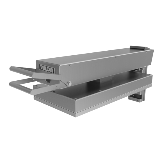
- Page 1 OPERATION AND FIELD INSTALLATION MANUAL GTS Heavy Duty Electric Griddle Top MODELS GTS12-1 GTS12-2 GTS12-3R GTS12-4R MODEL GTS12 RETAIN THIS MANUAL FOR FUTURE USE ©ITW Food Equipment Group, LLC 3600 North Point Blvd. Baltimore, MD 21222 FORM F-38300 (05-13)
-
Page 2: Table Of Contents
TABLE OF CONTENTS OPERATIONS Installation………………………………………………………………………………………….. Electrical Specifications…………………………………………………………………………… Controls…………………………………………………………………………………………….. Raising/lowering griddle top………………………………………………………………………. Using the griddle…………………………………………………………………………………… Cleaning…………………………………………………………………………………………….. Shutdown…………………………………………………………………………………………… Maintenance……………………………………………………………………………………….. FIELD INSTALLATION ASSEMBLY Tools required……………………………………………………………………………………… Mounting bracket assembly………………………………………………………………………. Mounting bracket installation……………………………………………………………………... Griddle top installation…………………………………………………………………………….. Flue deflector installation…………………………………………………………………………. Tension rod spring assembly…………………………………………………………………….. Range of motion…………………………………………………………………………………… Electrical connections and specifications………………………………………………………. -
Page 3: Installation
Before installing, check the electrical service to make sure it agrees with the specifications on the rating plate. If the supply and equipment voltages do not agree, do not proceed with the installation. Contact your dealer or Vulcan-Hart immediately. INSTALLATION CODES AND STANDARDS... -
Page 4: Controls
Remove all packaging material and protective plastic from the unit. It is recommended that you clean your Vulcan GTS griddle top thoroughly with a mild soap and water. Wipe the griddle surface thoroughly with water and wipe dry with a soft clean cloth. -
Page 5: Raising/Lowering Griddle Top
High Limit Reset Access Plug Thermostat Adjustment Knob Thermostat Cover Power Switch Trigger Handle High Limit Reset Button Fig. A Amber Indicator Lights Power Light (Left) Heating Light (Right) To raise the assembly to the 47˚ position 1. Lift by the handle only 2. -
Page 6: Using The Griddle
USING THE ELECTRIC GRIDDLE To preheat, wipe the griddle top plate with cooking oil and set the thermostats for the desired temperatures 10-12 minutes before cooking. A uniform and systematic approach to loading the griddle will produce the most consistent product results. -
Page 7: Shutdown
ONCE PER DAY Thoroughly clean all stainless steel exterior panels and surfaces. Clean the cooking surface with a non-metallic scouring pad (Scotch-Brite™). ONCE PER WEEK Clean the griddle surface thoroughly. A mild detergent solution may be used on the plate surface to help clean it, but be sure the detergent is thoroughly removed by wiping down with clear water. -
Page 8: Maintenance
MAINTENANCE The griddle and its parts are hot. Use care when operating, cleaning or servicing the griddle. Disconnect power supply and follow lockout / tagout procedures before cleaning and servicing the appliance. LUBRICATION There are no parts on this unit that require lubrication. SERVICE AND PARTS INFORMATION Contact the Authorized Service Agency in your area to obtain service and parts information. -
Page 9: Mounting Bracket Assembly
ASSEMBLY The griddle and its parts are hot. Use care when operating, cleaning or servicing the griddle. Disconnect power supply and follow lockout / tagout procedures before cleaning and servicing the appliance. Prior assembly, make sure mounting bracket is the correct size. The back bracket should match the width of the griddle. - Page 10 4. Securely tighten the mounting bracket system assembly bolts at the left and right side mounting brackets. Fig. 4. 5. Check that the left and right mounting brackets have not moved from position while assembly bolts were tightened. The “F” clamps should still be in place to prevent the assembly Fig.
- Page 11 8. Drill the remaining holes through the side mounting brackets into the griddle chassis. Insert and tighten screws as shown in Fig. 7. Repeat procedure for the other side of the assembly. 9. Drill holes with 5/32” bits from the rear of the side mounting bracket into the back mounting bracket and install wall spacer with (4) 10-24 x ½”...
-
Page 12: Griddle Top Installation
It may be necessary to angle the griddle and hang one of the four legs off the edge of the table at a time to complete step 11. Ensure that the griddle is safely supported and this step is accomplished with aid of a second person. -
Page 13: Flue Deflector Installation
14. Place cardboard or other protective covering on the gas griddle surface to prevent scratching. 15. Set electric griddle top down on the gas griddle plate at desired mounting position. Lower rear arm assembly into place so that notches on arm engage Fig. - Page 14 17. Set lower mounting spacer in place. Apply a thread locking compound to (2) M10 hex bolts with lock washers. Insert the bolts through the mounting spacer and bracket. Thread into the mounting plate (set into place in step 13) and tighten.
-
Page 15: Tension Rod Spring Assembly
The electric griddle top should be securely attached to the mounting brackets and raised in the locked 90° position before proceeding. Attempting to install tension springs in lowered position may cause damage. TENSION SPRING INSTALLATION Fig. 16 18. Raise the electric griddle top to the locked 90°... -
Page 16: Range Of Motion
20. Reinstall the tension rod cover and tighten screws. Fig. 18 21. Check range of motion as shown in Fig. 19. The assembly should lock at the 90˚ and 47˚ positions. Assembly should release from locked positions when handles are squeezed together. Do not force unit down, it should lower under its own weight when the handles are squeezed. -
Page 17: Electrical Connections And Specifications
ELECTRICAL CONNECTIONS Electrical grounding connections must comply with applicable portions of the National Electrical Code and/or other local electrical codes. Disconnect the electrical power to the griddle and follow lockout / tagout procedures. Since the griddle top is not fused, you must connect to a fused circuit equipped with a suitable disconnecting means as required by local authorities. -
Page 19: Troubleshooting
TROUBLESHOOTING PROBLEM POSSIBLE CAUSES 1. Thermostat set too low. Turn to higher setting 2. High limit cutoff switch is tripped – depress reset button. Heat does not come on 3. If power switch is not illuminated. Check breaker panel. when power switch is 4. -
Page 20: Accessories
ACCESSORIES GTS12 ELECTRIC GRIDDLE TEFLON WRAP KIT INSTALLATION The griddle and its Teflon Sheet Sleeve parts hot. care when operating, cleaning or servicing the Teflon Bracket griddle. 1. Clean off platen using soft cloth, water and mild soap solution. 2. Slide the Teflon bracket (#944503) into the sleeve of the Teflon sheet as shown in fig. - Page 21 3. Using water, rinse the Teflon sheet and hardware thoroughly on both sides. 4. Dry the Teflon sheet and hardware using a clean soft cloth. 5. Before reassembling the Teflon sheet to the platen, clean the platen as described in Care and Cleaning section.
- Page 22 NOTES...
Need help?
Do you have a question about the GTS12-1 and is the answer not in the manual?
Questions and answers