Table of Contents

Related Manuals for Vulcan-Hart VTEC14


Summary of Contents for Vulcan-Hart VTEC14
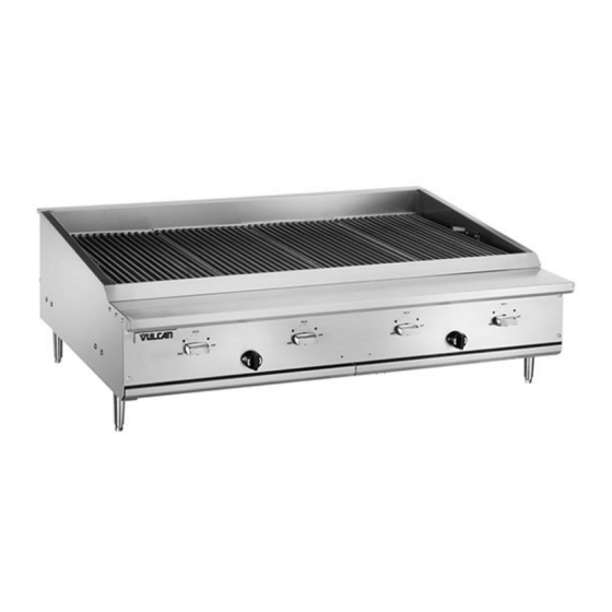
- Page 1 INSTALLATION & OPERATION MANUAL GAS INFRARED CHARBROILER MODELS VTEC14 VTEC25 VTEC36 VTEC48 VTEC60 VTEC48 RETAIN THIS MANUAL FOR FUTURE USE ©ITW Food Equipment Group, LLC 3600 North Point Blvd. Baltimore, MD 21222 FORM F38330 (11-11)
-
Page 2: Important For Your Safety
IMPORTANT FOR YOUR SAFETY THIS MANUAL HAS BEEN PREPARED FOR PERSONNEL QUALIFIED TO INSTALL GAS EQUIPMENT, WHO SHOULD PERFORM THE INITIAL FIELD START-UP AND ADJUSTMENTS OF THE EQUIPMENT COVERED BY THIS MANUAL. POST IN A PROMINENT LOCATION THE INSTRUCTIONS TO BE FOLLOWED IN THE EVENT THE SMELL OF GAS IS DETECTED. - Page 3 INSTALLATION, OPERATION AND CARE OF GAS COUNTERTOP CHARBROILERS GENERAL Gas Infrared Charbroilers are designed for commercial use only and feature fast, efficient gas heat. Each burner is controlled by an adjustable gas valve. Emitter panels are located directly above each burner to maintain uniform temperature and provide infrared cooking.
- Page 4 LOCATION The installation location must be kept free and clear of combustibles. Do not obstruct the flow of combustion and ventilation air. DO NOT install the charbroiler adjacent to open burners or fryers. Sufficient air should be allowed to enter the room to compensate for the amount of air removed by any ventilating system and for combustion of the gas burners.
-
Page 5: Key Components
KEY COMPONENTS The charbroiler Cooking Grid and its parts are hot. Use care when operating, cleaning Emitter Panel servicing the charbroiler. Burner Cooking Grids – The cooking grids should always be in place and properly seated on the emitter panels during operation. -
Page 6: Ventilation Hood
LEVELING It is important that the charbroiler is level front to back and left to right. Areas of uneven heat distribution will occur on an unleveled unit. The charbroiler is equipped with adjustable legs. Turn the feet at the bottom of the legs to adjust to level. The unit should be rechecked for level anytime it has been moved. - Page 7 Prior to lighting, check all joints in the gas supply line for leaks. Use soap and water solution. Do not use an open flame. GAS PRESSURE REGULATOR INSTALLATION Gas regulator pressure is preset at 4” Water Column (W.C.) for natural gas, and 10” W.C. for propane gas.
-
Page 8: Operation
OPERATION The charbroiler and its parts are hot. Use care when operating, cleaning or servicing the charbroiler. BURNER LIGHTING The VTEC charbroiler does not have a pilot and each burner lights directly from a spark igniter or from an outside ignition source (such Burner Sight Hole as a lit taper, long handle lighter, etc). - Page 9 LIGHTING BURNER MANUALLY 1. Turn the main gas shut-off valve and the individual burner control knobs to the OFF Outside Ignition Source Emitter Panel position (clockwise until stops). Wait 5 minutes. 2. Apply a flame from an outside ignition source (such as a lit taper, long handle lighter, etc) directly to the gap between the bottom of the emitter panel and the top of the intended...
- Page 10 CLEANING The charbroiler and its parts are hot. Use care when operating, cleaning or servicing the charbroiler. Scrape cooking grids during broiling with a stainless steel scraper or stainless steel wire brush to keep the grates clean. Do not allow debris to accumulate on the grates.
-
Page 11: Maintenance
Never cover surface of unit with pans or other objects in attempt to “burn off” or clean debris from unit. This will cause a buildup of heat that can potentially damage and warp components of the charbroiler. Do not cover surfaces with aluminum foil as this may block or disrupt the designed air flow pattern and affect performance. -
Page 12: Troubleshooting
TROUBLE SHOOTING Uneven heating A. Burner valves improperly adjusted B. Fluctuating gas pressure C. Appliance is not level D. Emitter panels are not properly seated or damaged E. Emitter panels are excessively dirty Too much top heat A. Faulty hood ventilation C. - Page 13 NOTES...
- Page 16 REMARQUES...
- Page 17 régulateur ventilation obstruction pour Contrôlé pression Variation haute trop Pression hautes endommagés placés émetteurs Panneaux trop brûleurs Flammes brûleur l’orifice Obstruction sale excessivement brûleur brûleur boîtier L'intérieur basse trop Pression basses réglés brûleurs Boutons trop brûleurs Flammes sale excessivement brûleur brûleur boîtier L'intérieur...
-
Page 18: Entretien
série. numéro modèle numéro l’appareil signalétique fiche disponibles être devraient suivants renseignements service, pour appelez vous Lorsque www.vulcanequipment.com.. consultez pièces, services bureaux liste Pour équipement. nécessaire réglage tout réparation toute pour local clientèle à service votre avec Communiquez SERVICE coincement. signe premier dès... - Page 19 prématurément. endommager corrosion processus accélérer peut nettoyage cuisson après humides panneaux laisser fait nettoyage. après humides émetteurs panneaux jamais laissez NOTEZ (Fig. vidé. refroidi fois ramasse-miettes Fig. Retirez débris. débarrassé soit brûleurs boîtiers l'intérieur à Veillez émetteur. panneau parois débris accumulation toute enlever...
- Page 20 complet). l'arrêt jusqu'à montre d'une aiguilles sens dans (tournés » FERMÉ « sont brûleurs individuels boutons Assurez-vous ». FERMÉ « principal d'alimentation robinet Tournez complètement fermer Pour BRULEURS COMPLÈTE FERMETURE suivant. brûleur allumer Fig. à continuer avant allumé brûleur brûleurs commande Bouton vérifiez...
- Page 21 Fig. Voir d'énergie. économie pour lente cuisson à (minimum) régler peuvent brûleurs cuisson. pendant d'efficacité maximum pour (maximum) régler doivent brûleurs principal d'arrêt robinet tournez point, à allumé encore bruleur plus. fois deux l'étape répétez immédiatement, s'allume brûleur brûleur. regard Fig.
- Page 22 installé. être doit où l'endroit à gril replacez l’alimentation d’ouvrir avant dispositif Rebranchez débranchement. avant l’alimentation fermez nécessaire, dispositif débranchement gril. l’arrière à retenue dispositif Attachez associées. conduites leurs rapide démontage à prise dispositif connecteur dépendre sans gril mouvement limiter pour apportées doivent...
- Page 23 d’essai pressions Lorsque gaz. l’alimentation tuyauterie déconnectés être doivent individuel d’arrêt robinet gril kPa), (3,45 ½ excèdent d’essai pressions gaz, l’alimentation tuyauterie évaluez vous Lorsque notable. baisse démontrer devrait éléments tous d’admission pression temps, même fonctionnant éléments tous Avec propane. pour naturel pour...
- Page 24 Fig. Voir haut. Fig. vers pointés saillants rebords avec positionnés être doivent émetteurs panneaux brûleur. chaque place émetteur Panneau au-dessus arrière avant brûleurs fixations dans latéraux brûleurs fixations s'appuyer doivent émetteurs panneaux émetteur infrarouge. à cuisson ainsi panneau rebords avant/arrière facilitant l'énergie répandent...
- Page 25 Canada Ontario, Etobicoke, Rexdale, boul. Gaz, Canadienne l’Association auprès disponible édition), (dernière CAN/CSA-B149.2 propane d'installation Code édition) (dernière CAN/CSA-B149.1 naturel d'installation Code locaux. Codes Canada 02269. Quincy, Park, Batterymarch Association, Protection Fire National l'organisme auprès disponible édition, dernière Equipment, Cooking from Removal Vapor...
-
Page 26: Installation
droit. avant supérieur côté située plaque spécifiées normes conformes sont dégagement espaces propane) (naturel type vérifiez l'installation, Avant manuel). dans PRESSION RÉGULATEUR INTALLATION (Consultez service soit gril avant installé être doit fourni été brûleur avec fonctionner pour conçu pression régulateur l’emballage. - Page 27 APPAREIL. FONCTIONNER FAIRE TENTER COURANT, PANNE équipement. servir d’installer avant d’entretien d’emploi d’installation, instructions minutieusement Lire mort. blessure matériel, dommage causer peut inapproprié entretien service modification, ajustement, installation, GARDE MISE APPAREIL. AUTRE TOUT APPAREIL PROXIMITÉ À INFLAMMABLES LIQUIDES VAPEURS AUTRES L’ESSENCE UTILISER ENTREPOSER...
- Page 28 (11-11) F38330 FORM 21222 Baltimore, Blvd. Point North 3600 FUTURE UTILISATION Group, Equipment Food ©ITW POUR MANUEL GARDER VTEC48 VTEC60 VTEC48 VTEC36 VTEC25 VTEC14 MODÈLES À INFRAROUGE GRIL D'EMPLOI D'INSTALLATION MANUEL...
Need help?
Do you have a question about the VTEC14 and is the answer not in the manual?
Questions and answers