
Related Manuals for M/A-Com M/A-COm P5200 Series


Summary of Contents for M/A-Com M/A-COm P5200 Series
- Page 1 Operator’s Manual MM23772 Rev. F, Jul/08 M/A-COM P7200 and P5200 Series Portable Radios...
- Page 2 M/A-COM Technical Publications would particularly appreciate feedback on any errors found in this document and suggestions on how the document could be improved. Submit your comments and suggestions to: Tyco Electronics Wireless Systems Segment M/A-COM, Inc. Fax your comments to: 1-434-455-6851...
-
Page 3: Table Of Contents
MM23772, Rev. F TABLE OF CONTENTS Page SAFETY CONVENTIONS........................10 SAFETY TRAINING INFORMATION ....................11 RF EXPOSURE GUIDELINES ....................11 ELECTROMAGNETIC INTERFERENCE/COMPATIBILITY..........12 OPERATING TIPS ..........................13 EFFICIENT RADIO OPERATION ...................13 3.1.1 Antenna Care and Replacement..................13 3.1.2 Electronic Devices ......................13 3.1.3 Aircraft...........................14 3.1.4 Electric Blasting Caps ....................14 3.1.5 Potentially Explosive Atmospheres................14 BATTERIES ............................15... - Page 4 MM23772, Rev. F TABLE OF CONTENTS Page 8.8.1 Profiles...........................30 8.8.2 Talk Groups ........................30 OPENSKY DISPLAY OVERVIEW..................31 8.9.1 Display’s Top Line ......................31 8.9.2 Display’s Second Line....................31 8.9.3 Dwell Display ........................31 8.10 ALERT TONES..........................32 8.11 BASIC MENU STRUCTURE....................33 8.12 ERROR MESSAGES .........................35 8.13 KEYPAD ............................37 8.13.1 Keypad Function Commands (P7270 Only)..............37...
- Page 5 MM23772, Rev. F TABLE OF CONTENTS Page 8.27.1 Declare an Emergency Call or Alert................49 8.27.2 Receive an Emergency Call...................50 8.27.3 Dismiss an Emergency ....................50 8.27.4 Clear an Emergency.......................50 8.28 OPENSKY ENCRYPTION (P7200 ONLY)................51 8.28.1 Automatic Encryption....................51 8.28.2 Manual Encryption (P7270 Only) .................51 8.29 DYNAMIC REGROUPING ......................52 8.30...
- Page 6 MM23772, Rev. F TABLE OF CONTENTS Page 9.20.1 Turn Scan On and Off....................73 9.20.2 Add Groups to a Scan List.....................74 9.20.3 Delete Groups from a Scan List..................75 9.20.4 Nuisance Delete ......................76 9.21 SCAN TRUNKED SYSTEMS....................76 9.21.1 Wide Area System Scanning ..................76 9.21.2 Priority System Scan......................76 9.21.3 ProScan..........................77 9.22...
- Page 7 MM23772, Rev. F TABLE OF CONTENTS Page 10.7 SYSTEM SELECTION......................93 10.8 GROUP/CHANNEL SELECTION....................94 10.9 MODIFY SCAN LIST .......................94 10.9.1 P7270 System Model.....................94 10.9.2 P7250 and P5250 Model....................95 10.10 NUISANCE DELETE (P7270 MODEL) ...................95 10.11 BACKLIGHT ON/OFF ......................95 10.12 CONTRAST ADJUST .......................95 10.13 DECLAR AN EMERGENCY....................96 10.14 LOCK/UNLOCK KEYPAD ......................96 10.15 HIGH/LOW POWER ADJUSTMENT ..................96...
- Page 8 MM23772, Rev. F TABLE OF CONTENTS Page 11.12 CONTRAST ADJUST ......................112 11.13 DECLARE AN EMERGENCY ....................112 11.14 LOCK/UNLOCK KEYPAD ....................113 11.15 HIGH/LOW POWER ADJUSTMENT ..................113 11.15.1 Using the Menu Button....................113 11.15.2 Using the Pre-Programmed Option Button..............113 11.16 MENU ............................113 11.16.1 Menu Item Selection Process..................114 11.17 RECEIVE A CALL ........................116 11.18 TRANSMIT A CALL.......................116 12 TECHNICAL ASSISTANCE ......................117...
- Page 9 MM23772, Rev. F TABLE OF CONTENTS Page Figure 11-3: P7270 Radio Front Panel ......................107 Figure 11-4: Radio Display.......................... 108 Figure 11-5: Tri-Color LED......................... 109 Figure 11-6: Menu Display .......................... 113 Figure 11-7: Backlight Menu Display ......................114 TABLES Table 2-1: RF Exposure Compliance Testing Distances ................12 Table 6-1: Options and Accessories.......................
-
Page 10: Safety Conventions
MM23772, Rev. F SAFETY CONVENTIONS The following conventions are used throughout this manual to alert the user to general safety precautions that must be observed during all phases of operation, service, and repair of this product. Failure to comply with these precautions or with specific warning elsewhere in this manual violates safety standards of design, manufacture, and intended use of the product. -
Page 11: Safety Training Information
MM23772, Rev. F SAFETY TRAINING INFORMATION The M/A-COM P7200 and P5200 portable radios generate RF electromagnetic energy during transmit mode. This radio is designed for and classified as “Occupational Use Only,” meaning it must be used only during the course of employment by individuals aware of the hazards and the ways to minimize such hazards. -
Page 12: Electromagnetic Interference/Compatibility
MM23772, Rev. F • As noted in Table 2-1, ALWAYS keep the device and its antenna AT LEAST 1.1 cm (0.43 inches) from the body and at least 2.5 cm (1.00 inch) from the face when transmitting to ensure FCC RF exposure compliance requirements are not exceeded. -
Page 13: Operating Tips
MM23772, Rev. F OPERATING TIPS Antenna location and condition are important when operating a portable radio. Operating the radio in low lying areas or terrain, under power lines or bridges, inside of a vehicle or in a metal framed building can severely reduce the range of the unit. -
Page 14: Aircraft
MM23772, Rev. F 3.1.3 Aircraft Always turn off a portable radio before boarding any aircraft! Use it on the ground only with crew permission. DO NOT use while in-flight!! 3.1.4 Electric Blasting Caps To prevent accidental detonation of electric blasting caps, DO NOT use two-way radios within 1000 feet of blasting operations. -
Page 15: Batteries
MM23772, Rev. F BATTERIES The P7200 and P5200 series portable radios use rechargeable, recyclable Nickel Cadmium (NiCd), Nickel Metal Hydride (NiMH), or Lithium Ion (Li Ion) batteries. Please follow the directions below to maximize the useful life of each type of battery. Do not disassemble or modify Lithium Ion battery packs. -
Page 16: Charging Battery Packs
MM23772, Rev. F CHARGING BATTERY PACKS Battery chargers are available from M/A-COM with nominal charge times of one hour. Combinations include single and multi-position, rapid charge units. M/A-COM chargers are specifically designed for charging nickel-based and lithium ion battery packs. The chargers are chemistry-specific for the battery packs and automatically adjust the charging profiles accordingly. -
Page 17: Change The Battery Pack
MM23772, Rev. F CHANGE THE BATTERY PACK 4.4.1 Remove the Battery Pack Make sure the power to the radio is turned OFF. Although the P7200 and P5200 have been designed to tolerate changing the battery pack without turning power off, M/A-COM, Inc. recommends turning radios off before changing battery packs to ensure safety and best operation. -
Page 18: Battery Disposal
MM23772, Rev. F BATTERY DISPOSAL In no instance should a battery be incinerated. Disposing of a battery by burning will cause an explosion. CAUTION RECHARGEABLE BATTERY PACK DISPOSAL – The product you have purchased contains a rechargeable battery. The battery is recyclable. At the end of its useful life, under various state and local laws, it may be illegal to dispose of this battery into the municipal waste stream. -
Page 19: Introduction
MM23772, Rev. F INTRODUCTION The P7200 and P5200 series radios are dual-band multi-mode portable radios. The P7200 series radio is available without a front mounted keypad (P7200 only), with a 6-buttoned front mounted keypad, and with a DTMF front mounted keypad (P7200 only). The dual-band (700/800 MHz) P7200 portable radio delivers end-to-end encrypted digital voice and IP data communications. -
Page 20: Figure 5-1: P7230 Select Model Radio
MM23772, Rev. F Figure 5-1: P7230 Select Model Radio Figure 5-2: P7250 and P5250 Scan Models... -
Page 21: Water Resistance (P7200 Only)
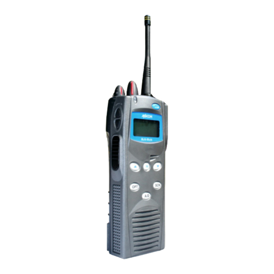
MM23772, Rev. F Figure 5-3: P7270 System Model WATER RESISTANCE (P7200 ONLY) The P7200 series portable radios operate reliably even under adverse conditions. These radios meet MIL- STD-810F specifications for driven rain, humidity, and salt fog. UNIVERSAL DEVICE CONNECTOR (UDC) The Universal Device Connector (UDC) provides connections for external accessories such as a headset or a speaker-microphone and for programming cables. -
Page 22: Options And Accessories
MM23772, Rev. F OPTIONS AND ACCESSORIES Table 6-1 lists the Options and Accessories tested for use with the P7200 and P5200 series portable radios. Refer to the maintenance manual or to M/A-COM’s Products and Services Catalog for a complete list of options and accessories, including those items that do not adversely affect the RF energy exposure. - Page 23 MM23772, Rev. F DESCRIPTION PART NUMBER Speaker Microphone, Ant. Version, Ruggedized, Charger Compatible KRY 101 1617/387 Metal Belt Clip KRY 101 1647/1 Belt Loop with Swivel KRY 101 1609/1 Swivel (part of KRY 101 1639 and 1648) KRY 101 1608/2 Leather Case (Belt Loop type) KRY 101 1638/1 Leather Case Kit (with Leather Case P/N: KRY 101 1639/1)
-
Page 24: Change Operating Mode
MM23772, Rev. F CHANGE OPERATING MODE CHANGE FROM OTP MODE To change from OTP operating mode to P25/EDACS/Conventional: 1. Use to cycle through the menu until “App Mode” is displayed. 2. Use to choose an available mode. Press to confirm (Y/N). 3. -
Page 25: Opensky Operation
MM23772, Rev. F OPENSKY OPERATION Once an OpenSky system has been selected from the available systems on your P7200 or P5200 series portable radio, the characteristics described in the following sections will govern operation. POWER ON/OFF AND VOLUME CONTROL 8.1.1 Power ON/OFF Rotate the Power ON/OFF/Volume knob clockwise to power the radio on and counter-clockwise to power the radio off. -
Page 26: Buttons And Knobs
MM23772, Rev. F 8.2.1 Buttons and Knobs The function of the button and knob controls will vary depending on the mode of operation. The primary functions of the button and knob controls when in the OpenSky mode of operation are listed in the following paragraphs. -
Page 27: Keypad (P7250, P5250, And P7270)
MM23772, Rev. F 8.2.2 Keypad (P7250, P5250, and P7270) The keys on the keypad have special functions and are labeled using a symbol or abbreviated word describing its primary function. Numeric entry is a secondary function of the keys. Table 8-1 lists and defines each key. -
Page 28: Display
MM23772, Rev. F DISPLAY The P7200 and P5200 display (Figure 8-2) is made up of 3 lines. Lines 1 and 2 contain twelve alpha-numeric character blocks each. The 3 line displays radio status icons. If programmed, the display backlighting will illuminate upon power up or when operating radio controls. See the operation sections of this manual for specific display characteristics. -
Page 29: Tri-Color Led
MM23772, Rev. F TRI-COLOR LED Figure 8-3: Tri-Color LED The Tri-Color LED changes color to indicate radio status and is visible from both the front and top of the radio (see Figure 8-3). The LED can be turned On or Off via the “Status LED” menu option. Green: Receiving. -
Page 30: Log Off The Network
MM23772, Rev. F LOG OFF THE NETWORK The *0## command de-registers the radio. Typically, this is automatically performed when powering down the radio. Using this method, the User ID is remembered by the radio so only the password is needed at next log-in. Log-off manually by pressing *0##. PERSONALITY As illustrated in Figure 8-4, a personality defines the profiles and talk groups available to the user. -
Page 31: Opensky Display Overview
MM23772, Rev. F OPENSKY DISPLAY OVERVIEW The 12-character x 3-line display shows the radio status. The first two lines of the display are text lines that change in response to user interaction with the menu buttons. Status icons appear in the bottom line (line 3) of the display (see Table 8-2). -
Page 32: Alert Tones
MM23772, Rev. F 8.10 ALERT TONES The P7200 and P5200 radios provide audible Alert Tones or “beeps” to indicate the various operating conditions (see Table 8-3). Table 8-3: Alert Tones NAME TONE DESCRIPTION Call Queued 1 low tone/2 high tones Call queued for processing. -
Page 33: Basic Menu Structure
MM23772, Rev. F 8.11 BASIC MENU STRUCTURE Table 8-4 illustrates the basic P7200 and P5200 OpenSky menu structure. Menu items will vary depending upon system programming, radio hardware, and optional configurations. All menus except the dwell display menu can be turned off by network administration personnel. Scroll through available menu options using the buttons. - Page 34 MM23772, Rev. F MENU RADIO USAGE NOTES NAME DISPLAYS See Previous Page Selected “ChannelMenu” Displays the current channel. Press to return to dwell display. Channel to scroll through available scan modes (Normal, No Scan, or Fixed). Scan Mode “ScnModeMenu” Press to return to dwell display.
-
Page 35: Error Messages
MM23772, Rev. F 8.12 ERROR MESSAGES This section lists and describes the error messages that may be displayed by the P7200 during OpenSky operation. MESSAGE DESCRIPTION NOAUT01 Unspecified MDIS error. If condition persists in strong signal conditions, contact your system administrator. MDENIED Unspecified MDIS error. - Page 36 MM23772, Rev. F MESSAGE DESCRIPTION BAD VID Invalid voice user ID. Check User ID. If correct, contact your system administrator. HOM DWN The Home VNIC is down. Retry. If error continues, contact your system administrator. SRV BSY The serving VNIC is busy (congested). MAX USR The maximum number of users are already registered with the specified user ID.
-
Page 37: Keypad
MM23772, Rev. F 8.13 KEYPAD 8.13.1 Keypad Function Commands (P7270 Only) To perform a command from the keypad, use one of the keypad commands: Table 8-5: Keypad Function Commands KEYPAD FUNCTION COMMAND Log-off command: *0## (logs the user off the system). See Section 8.7 for additional information. -
Page 38: Quick Buttons (P7270 Only)
MM23772, Rev. F 8.13.2 Quick Buttons (P7270 Only) Quick Buttons are a two-button sequence that gives the radio user quick access to certain menu items. Quick Buttons act as a toggle function. Table 8-6: Quick Buttons QUICK FUNCTION KEYS Transition to ECP mode If ECP is not loaded in the radio, the radio displays “No App.”... -
Page 39: Change The Active Profile
MM23772, Rev. F When a key on the DTMF keypad is pressed, the DTMF tone is played through the radio’s speaker. 8.14 CHANGE THE ACTIVE PROFILE The radio can store up to sixteen (16) standard profiles, one of which is the currently active profile. To change the currently active profile: 1. -
Page 40: Adjust Side Tone Audio Level
MM23772, Rev. F On P7250 model radios, when stealth mode is on, pressing any radio button (other than the mic’s PTT button or the emergency button) on front panel will immediately turn stealth mode off. For example, pressing the button on the front panel will turn stealth mode off. -
Page 41: Transmit A Voice Call
MM23772, Rev. F b. If the received talk group does not match the selected talk group, then the received talk group name is displayed. • When the dwell display is set to received talk group and the scan mode is None, the radio only receives voice on its selected talk group. -
Page 42: Lock Out A Talk Group
MM23772, Rev. F P1 and P2 groups CANNOT be locked out. The default emergency and emergency-capable talk groups can be locked out if they are NOT in an emergency state. If a talk group is locked out and is subsequently changed to the currently selected talk group, it will automatically be unlocked by the radio so the user can hear calls on the talk group. -
Page 43: Change Active Scan Mode
MM23772, Rev. F Table 8-7: Scan Modes SCAN EXPLANATION MODE Eliminates distractions. Full communications (listen and talk) with the active talk group. No Scan No calls received from other talk groups. This is the default setting. The user can scan all talk groups in the active profile that are not locked out as long as there is demand on the site. -
Page 44: Scan Priority
MM23772, Rev. F 8.23.3 Scan Priority The following lists the scan priority order (from highest to lowest): • Selected talk group in emergency state. • Default emergency group in emergency state. • Selected talk group. • Emergency capable group in emergency state. •... -
Page 45: Manually Dialing A Selective Call (P7270 Only)
MM23772, Rev. F 8.24.1 Manually Dialing a Selective Call (P7270 Only) 1. Enter *8, the User ID number of the user being called, and the # key (no dashes or spaces). This feature must be enabled by the administrator. *8<destination user id># A shortened User ID number can be dialed using the following guidelines: •... -
Page 46: Accept A Selective Call
MM23772, Rev. F 2. Press and hold a key associated with a given number for more than three seconds. For example, press and hold the to open the Speed Dial Menu and display the third number in the speed dial list. Press the PTT button. -
Page 47: Send A Message
MM23772, Rev. F Table 8-9 lists and defines the messages that may be displayed by the radio during a Selective Alert. Table 8-9: Status of Selective Alert Messages STATUS MESSAGE DEFINITION Alert Sent Alert message successfully sent to target. Delivered Alert message passed to network. -
Page 48: Receive A Message
MM23772, Rev. F 8.25.2.2 Select a Destination Using the Menu 1. Using the key, scroll through the menu until “AlertDst” (Alert Destination) appears. 2. Use the button to scroll through the list of User IDs until the desired destination is displayed and press the key. -
Page 49: Receive An Interconnect Call
MM23772, Rev. F 8.26.2 Receive an Interconnect Call Press , or buttons to accept an incoming Interconnect Call. 8.27 EMERGENCY COMMUNICATIONS The P7200 and P5200 portable radios are capable of sending an emergency alert and making emergency calls on the network. The OpenSky system handles emergency calls with the highest priority, allowing you or the people you serve to get needed help. -
Page 50: Receive An Emergency Call
MM23772, Rev. F alternate between the emergency talk group name and “EMERGENCY” to indicate that the emergency has been initiated. 2. The microphone is hot (open mic) for a programmed amount of time in order to send your voice out on the emergency talk group. -
Page 51: Opensky Encryption (P7200 Only)
MM23772, Rev. F 8.28 OPENSKY ENCRYPTION (P7200 ONLY) In the OpenSky network, both data and voice use a 128-bit or 256-bit key encryption standard published by the Federal Information Processing Service (FIPS), called Advanced Encryption Standard (AES). AES is approved by the U.S. Department of Commerce for encryption of classified materials. When encryption is enabled on the network, data is encrypted from the MDIS to the Mobile End System (MES) (e.g., P7200 portable radio). -
Page 52: Dynamic Regrouping
MM23772, Rev. F 8.28.2.1 Using Manual Encryption 1. Press *32 on the keypad. 2. Enter the key (1 – 16 digits for 128 bit encryption; 17 – 32 digits for 256 bit encryption). 3. Press #. 4. To end manual encryption, press *33. If a user is engaged in a call on a talk group that has been manually encrypted at the radio level, the user will see “Secure Call”... -
Page 53: Change Between Extended Coverage Modes
MM23772, Rev. F The V-TAC supports two Extended Coverage modes: Extended Coverage for individual users (XCOV) and Extended Coverage for a talk group (XCOV-TG). Typically, Extended Coverage is used after the vehicle’s operator has exited the vehicle with a portable radio unit and the portable unit requires this bridging functionality to access the OpenSky radio network. -
Page 54: Use The Xcov-Tg Mode
MM23772, Rev. F 8.31.4 Use the XCOV-TG Mode When using the XCOV-TG mode, up to thirty (30) client radios can connect to the V-TAC. However, unlike XCOV, radios connected to using XCOV-TG are limited to communicating only on the XCOV-TG talk group and emergency communications. Advanced features such as selective calling and mobile data operations are not available to the XCOV-TG connected clients. -
Page 55: Use The Scene-Of-Incident Mode
MM23772, Rev. F 8.31.5 Use the Scene-of-Incident Mode The Scene-of-Incident mode (SOI) is user-selectable. The SOI mode provides a local repeater function (V-TAC) with no network connection When operating in the SOI mode, the radio is disconnected from the OpenSky network. Therefore, communications with radios and dispatch personnel on the network is not possible. -
Page 56: Table 8-11: Band Definitions
MM23772, Rev. F Table 8-11: Band Definitions RF BAND RF CHANNEL NUMBER 0 = SMR Band 0: 1-830 1 = AMPS Band 1: 1-600 2 = BORDER Band 2: 1-600 3 = 700 MHz Band 1 Band 3: 1-477 4 = 700 MHz Band 2 Band 4: 481-957 5 = 700 MHz Band 3 Band 5: 1-477... -
Page 57: Edacs And P25 Trunked Operation
MM23772, Rev. F EDACS AND P25 TRUNKED OPERATION TURN ON THE RADIO 1. Power ON the radio by rotating the POWER ON/OFF/VOLUME knob clockwise. A short alert signal (if enabled through programming) indicates the radio is ready to use. Refer to Figure 9-1 for location of the POWER ON/OFF/VOLUME knob. -
Page 58: Buttons And Knobs
MM23772, Rev. F 9.2.1 Buttons and Knobs This section describes the primary function of the button and knob controls. Other functions associated with these controls are detailed in later sections. POWER ON-OFF Applies power to and adjusts the receiver’s volume. Rotating the control clockwise VOLUME KNOB applies power to the radio. -
Page 59: Keypad (P7250, P5250, And P7270)
MM23772, Rev. F 9.2.2 Keypad (P7250, P5250, and P7270) The keys on the keypad have special functions and are labeled using a symbol or abbreviated word describing its primary function. Numeric entry is a secondary function of the keys. Each key is described in Table 9-1 and Table 9-2. -
Page 60: Figure 9-3: P7270 Radio Front Panel
MM23772, Rev. F Figure 9-3: P7270 Radio Front Panel Table 9-2: P7270 Keypad Functions FUNCTION Primary Function: Allows the user to scroll through available systems, groups, or channels, depending on personality programming. Secondary Function: Changes the selection for an item within a list. Primary Function: Accesses the pre-stored menu. -
Page 61: Display
MM23772, Rev. F DISPLAY The radio display is made up of 3 lines (see Figure 9-4) containing twelve character blocks. Lines 1 and 2 primarily display system and group names. Line 1 also displays radio status messages. The 3rd line is used primarily to display radio status icons. -
Page 62: Radio Status Icons
MM23772, Rev. F RADIO STATUS ICONS Status Icons indicate the various operating characteristics of the radio. The icons show operating modes and conditions and appear on the third line of the display (see Table 9-3). The battery icon indicates approximate level only, based on battery voltage. Table 9-3: Display Descriptions ICON DESCRIPTION... -
Page 63: Tri-Color Led
MM23772, Rev. F TRI-COLOR LED Figure 9-5: Tri-Color LED The Tri-Color LED changes color to indicate radio status and is visible from both the front and top of the radio (see Figure 9-5). The three colors of the LED and the status they represent are: Green: Receiving. -
Page 64: Error Messages
MM23772, Rev. F MESSAGE NAME DESCRIPTION TXEMER Transmit Indicates an emergency call has been transmitted on this radio. This Emergency message will be flashing on line two. VOL=40 Volume Level Indicates the current volume level. The volume level display ranges from OFF (silent) to 40 (loudest). -
Page 65: System Selection
MM23772, Rev. F SYSTEM SELECTION METHOD 1: From control knob: system selection programmed SYSTEM/GROUP/CHANNEL SELECTION control knob, select a system by turning the knob to the desired system number position (1-16). The display registers the new system name on line one. The button can be programmed to provide access to a “2 bank”... -
Page 66: Modify Scan List
MM23772, Rev. F METHOD 2: (P7270, P7250, and P5250 model radios) From keypad: If group selection is programmed as the primary function of select a group by pressing to scroll through the group list. The display registers the new group name on line two. -
Page 67: Nuisance Delete (P7270 Model)
MM23772, Rev. F 9.12 NUISANCE DELETE (P7270 MODEL) A channel can temporarily be deleted from the scan list if it is not the currently selected channel. 1. Turn Scan ON. 2. When the radio receives a call on the channel, press the . -
Page 68: High/Low Power Adjustment
MM23772, Rev. F 9.17 HIGH/LOW POWER ADJUSTMENT Transmit power adjustment is possible if enabled through programming. Within conventional systems, transmit power is adjustable on a per channel basis. Within EDACS and P25 trunked systems, transmit power is adjustable on a per system basis. There are two ways to toggle between high and low power: 9.17.1 Using the Menu Button... -
Page 69: Menu Item Selection Process
MM23772, Rev. F 9.18.1 Menu Item Selection Process An example of the menu item selection process and menu item parameter change is detailed below for the Backlight menu item. 1. Press . The menu mode is entered. 2. Press until the display shows: 3. -
Page 70: Table 9-6: Information Display
MM23772, Rev. F PARAMETER FEATURE DISPLAY COMMENT SETTING Transmit Power Select Menu Item: HIGH or LOW Selects radio output power mode. TX POWER Once Selected: POWER= Radio Revision Menu Item: Selects the information display to view. Informational Information REVISION display only (see Table 9-6). No user selectable settings. Toggle Scan On/Off SCAN ON/OFF... -
Page 71: Digital Voice Operation
MM23772, Rev. F 9.19 DIGITAL VOICE OPERATION Digital voice programmed systems have three (3) different voice modes: clear (analog), digital, and private (encrypted). The voice modes are programmed on a per-group basis within each trunked system. 9.19.1 Clear Mode The Clear Mode is a voice mode in which the radio transmits and receives only clear (analog) voice signals. -
Page 72: Private Operation (P7200 Only)
MM23772, Rev. F 9.19.3.1 Display the Currently Used Cryptographic Key Number To Display the Currently Used Cryptographic Key Number for either the system encryption key (for special call such as individual, phone, all, agency or fleet) or the group/channel key (for group or conventional calls), perform the following procedure: 1. -
Page 73: Scan Trunked Groups
MM23772, Rev. F 9.19.4.2 Transmit an Encrypted Call 1. Select the desired group or channel. 2. Place the radio in Private Mode by pressing key, and then follow the selection mode rules. On a System radio, the key can be used to toggle the Private Mode ON/OFF. When Private Mode is enabled, the icon is displayed. -
Page 74: Add Groups To A Scan List
MM23772, Rev. F 2. Toggle Scan operation OFF by again pressing (Scan model) or (System model). will disappear. • If the radio scans to a group other than the selected group then receives a call on the selected group, the radio will switch to the selected group. However, if the “scanned-to” group is programmed at a higher priority the radio will remain on the “scanned-to”... -
Page 75: Delete Groups From A Scan List
MM23772, Rev. F 2. Press . The current priority status of the group will be displayed in column 10 of line three for a time-out period. If the group is not part of the scan list the status will be blank. 3. -
Page 76: Nuisance Delete
MM23772, Rev. F 9.20.4 Nuisance Delete A group can also be deleted from the scan list, if it is not the currently selected group, by pressing the key (Scan model) or the key (System model) during scan operation while the radio is displaying the unwanted group. -
Page 77: Proscan
MM23772, Rev. F scan for the priority system is defined by the System Sample Time control, located in the ProScan Options dialog box. See Section 9.21.3 for more information on ProScan 9.21.3 ProScan The radio may be programmed for ProScan system scan operation for multi-site applications depending on the version of radio flash code. -
Page 78: Individual Calls
MM23772, Rev. F To clear the emergency, first press and hold the button. While continuing to hold the button, press the EMERGENCY button. (This will work if the radio is programmed to clear emergencies.) 9.23 INDIVIDUAL CALLS 9.23.1 Receive and Respond to an Individual Call When the radio receives an individual call (a call directed only to the user's radio), it un-mutes on the assigned working channel and displays . -
Page 79: Send An Individual Call
MM23772, Rev. F Figure 9-11: WHC Individual Call Display Pressing PTT will initiate an individual call to the displayed logical ID. Powering the radio OFF and ON will clear this list. 9.23.2 Send an Individual Call 9.23.2.1 Pre-Stored Individual Calls The following procedures describe how to initiate and complete a Pre-Stored Individual Call. -
Page 80: Telephone Interconnect Calls
MM23772, Rev. F any index other than 0 or toggle between the two lists by pressing the key. If wrap is enabled, the calls received list wraps on itself and not into the other list. Figure 9-12: Calls Received and Personality Lists The saved call list shows all ten storage locations. -
Page 81: Dual-Tone Multi-Frequency: Overdial/Conventional Mode
MM23772, Rev. F 3. A telephone ring will be heard from the speaker. When someone answers the phone, press the PTT button and speak into the microphone. Release the PTT button to listen to the callee. Unsuccessful interconnect signaling returns the radio to the normal receive mode and the number remains displayed until the special call is cleared or the time-out expires or another group or system is selected. -
Page 82: Programmable Entries
MM23772, Rev. F 3. Press to enter the overdial select/entry mode and follow the selection mode rules to call up a stored number from the phone list. is displayed. Press PTT to send the overdial sequence once. If the number needs to be transmitted again it must be selected or entered again (this prevents unwanted numbers from being sent the next time the PTT button is pressed during the call). -
Page 83: Message Operation
MM23772, Rev. F STATUS is selected you need to enter the number of the status message you intend to transmit. If no NO ENTRY status has been programmed for the selected number key, the radio will display . A valid selection will permit the status text to appear in the display for a pre-programmed time. -
Page 84: Portable Data
MM23772, Rev. F 9.29 PORTABLE DATA The P7200 and P5200 series portable radios, when operating in the P25 Trunked or EDACS configuration, permit either voice or data calls to be transmitted or received. The radio can handle only one type of call at a time; however, either data or voice is selected transparently by the operator through normal usage of the radio. -
Page 85: Scan Lockout Mode
MM23772, Rev. F 9.29.5 Scan Lockout Mode Following the transmission or reception of a data call, if scan is enabled, scanning will stop temporarily (two independent pre-programmed times; after a receive data call and after a transmit data call). During this time the scan indicator will flash to indicate that scan is enabled but temporarily suspended. -
Page 86: Project 25 (P25) Conventional Operation
MM23772, Rev. F 10 PROJECT 25 (P25) CONVENTIONAL OPERATION 10.1 TURN ON THE RADIO Power ON the radio by rotating the Power ON/OFF/Volume knob clockwise. A short alert signal (if enabled through programming) indicates the radio is ready to use. Refer to Figure 10-1 for location of the Power ON/OFF/Volume knob. -
Page 87: Buttons And Knobs
MM23772, Rev. F 10.2.1 Buttons and Knobs This section describes the primary function of the button and knob controls. Other functions associated with these controls are detailed in later sections. POWER ON-OFF Applies power to and adjusts the receiver’s volume. Rotating the control VOLUME KNOB clockwise applies power to the radio. -
Page 88: Keypad (P7250, P5250, And P7270)
MM23772, Rev. F 10.2.2 Keypad (P7250, P5250, and P7270) The keys on the keypad have special functions and are labeled using a symbol or abbreviated word describing its primary function. Numeric entry is a secondary function of the keys. Each key is described in Table 10-1 and Table 10-2. -
Page 89: Figure 10-3: P7270 "System" Radio Front Panel
MM23772, Rev. F Figure 10-3: P7270 “System” Radio Front Panel Table 10-2: P7270 Keypad Functions FUNCTION Primary Function: Allows the user to scroll through available systems, groups, or channels, depending on personality programming. Secondary Function: Changes the selection for an item within a list. Primary Function: Accesses the pre-stored menu. -
Page 90: Display
MM23772, Rev. F 10.3 DISPLAY The radio Display is made up of 3 lines (see Figure 10-4) that contain 12 character blocks. Lines 1 and 2 are used primarily to display system and group names. Line 1 also displays radio status messages. The 3rd line is used primarily to display radio status icons. -
Page 91: Radio Status Icons
MM23772, Rev. F 10.3.1 Radio Status Icons Status Icons indicate the various operating characteristics of the radio. The icons show operating modes and conditions and appear on the third line of the display (see Table 10-3). The battery icon indicates approximate level only, based on battery voltage. -
Page 92: Tri-Color Led
MM23772, Rev. F 10.4 TRI-COLOR LED Figure 10-5: Tri-Color LED The Tri-Color LED changes color to indicate radio status and is visible from both the front and top of the radio (see Figure 10-5). The three colors of the LED and the status they represent are: Green: Receiving. -
Page 93: Error Messages
MM23772, Rev. F 10.5.1 Error Messages If either of the Error Messages shown below is displayed, the radio is programmed incorrectly or needs servicing. DIG V ERR=XXXX (PowerUp only) xxxx DSP ERR DIG V ERR Where: is the error code and is the message. -
Page 94: Group/Channel Selection
MM23772, Rev. F If system selection is programmed to the SYSTEM/GROUP/CHANNEL knob, direct access to systems is not available. Press to scroll through different sets of 16 systems each (banks) if more than 16 systems are programmed into the radio. The systems within each bank are then selectable via the SYSTEM/GROUP/CHANNEL knob as described previously in METHOD 1. -
Page 95: P7250 And P5250 Model
MM23772, Rev. F 4. Press once to add as a normal group or channel. 5. Press twice to add as a Priority 2 group. 6. Press three times to add as a Priority 1 group. 7. Press to re-start scanning. 10.9.2 P7250 and P5250 Model 1. -
Page 96: Declar An Emergency
MM23772, Rev. F 10.13 DECLAR AN EMERGENCY 1. Press and hold the red Emergency/Home button (the length of time is programmable; check with the system administrator). 2. *TXEMER* flashes in the display, plus will be displayed. After 2-3 seconds the transmit icon turns off. -
Page 97: Menu Item Selection Process
MM23772, Rev. F Figure 10-6: Menu Display 3. The radio will continue to receive and transmit normally while in the menu function. 4. To scroll through the menu options use the keys. When the required menu item has been found align the cursor with the option then press to select it. -
Page 98: Table 10-5: Menu Item Information
MM23772, Rev. F The TX POWER menu item, when selected, toggles LOW/HIGH power. It does not use to scroll nor is an additional press of the button required. Table 10-5: Menu Item Information PARAMETER FEATURE DISPLAY COMMENT SETTING Keypad Lock Menu Item: Locked Locks the keypad. -
Page 99: Digital Voice Operation
MM23772, Rev. F Table 10-6: Information Display PRS - NAME Personality Name XXXXXXXX EEPR SIZ EEPROM Size RAM SIZ RAM Size FLSH SIZ Flash Size RF BAND Frequency Band HSD RATE Data Transfer Rate PRS VER Software Version DSP_ _RAM DSP Software Version FLASH Software FLSH - VER... -
Page 100: Private Mode (P7200 Only)
MM23772, Rev. F 10.17.3 Private Mode (P7200 Only) The Private Mode allows the radio to transmit encrypted messages and receive clear or private transmissions. The radio transmits private if the group/channel is programmed for private operation and forced operation is pre-programmed. If autoselect operation is pre-programmed and the radio is in the Private Mode, the radio transmits in the mode of the received call if the hang time is active. -
Page 101: Private Operation (P7200 Only)
MM23772, Rev. F If the cryptographic key(s) are zeroed, one or more keys must be transferred from the Keyloader into the radio before private communications may continue. 10.17.4 Private Operation (P7200 Only) 10.17.4.1 Receive an Encrypted Call When receiving, the radio automatically switches between clear or private operation. If the transmission being received is an encrypted transmission, it will be decrypted, the icon is displayed, the receiver will unsquelch and the message will be heard in the speaker. -
Page 102: Group Calls In P25 Mode
MM23772, Rev. F Conventional Digital or encrypted channels require Channel Guard on the channel to operate correctly. The voice coding technology embodied in this product is protected by intellectual property rights including patent rights, copyrights, and trade secrets of Digital Voice Systems, Inc. The user of this technology is explicitly prohibited from attempting to de-compile, reverse engineer, or to disassemble the Object Code, or in any other way convert the Object Code into a human-readable form. -
Page 103: Emergency Group Calls In P25 Mode
MM23772, Rev. F 3. When the radio receives a P25 call, the radio will unmute and the ID of the transmitting radio will appear in the display. 4. Press the PTT button to respond. 5. Unanswered calls will appear in the Who Has Called (WHC) list. 10.20 EMERGENCY GROUP CALLS IN P25 MODE There is no method available for a system-wide Emergency clear. -
Page 104: Conventional Operation
MM23772, Rev. F 11 CONVENTIONAL OPERATION The radio functions in the conventional mode when using conventional communications channels (non- trunked). 11.1 CONTROLS The radio features two rotary control knobs and an emergency button mounted on the top of the radio (Figure 11-1). -
Page 105: Buttons And Knobs
MM23772, Rev. F 11.1.1 Buttons and Knobs This section describes the primary function of the button and knob controls. Other functions associated with these controls are detailed in later sections. POWER ON/OFF Applies power to and adjusts the receiver’s volume. Rotating the control VOLUME KNOB clockwise applies power to the radio. -
Page 106: Keypad (P7250, P5250, And P7270)
MM23772, Rev. F 11.1.2 Keypad (P7250, P5250, and P7270) The keys on the keypad have special functions and are labeled using a symbol or abbreviated word describing its primary function. Numeric entry is a secondary function of the keys. Each key is described in Table 11-1 and Table 11-2. -
Page 107: Table 11-2: P7270 Keypad Functions
MM23772, Rev. F Figure 11-3: P7270 Radio Front Panel Table 11-2: P7270 Keypad Functions FUNCTION Primary Function: Allows the user to scroll through available systems, groups, or channels, depending on personality programming. Secondary Function: Changes the selection for an item within a list. Primary Function: Accesses the pre-stored menu. -
Page 108: Display
MM23772, Rev. F 11.2 DISPLAY The radio display is made up of 3 lines (see Figure 11-4). Lines 1 and 2 contain eight alphanumeric character blocks and are used primarily to display system and group names. Line 1 also displays radio status messages. -
Page 109: Tri-Color Led
MM23772, Rev. F ICON DESCRIPTION Steady (rotates clockwise) – Scan mode enabled. If icon is not visible – Scan is disabled. Steady – Channel Guard enabled. If icon is not visible – Channel Guard is disabled. T99 Mode enabled. 11.3 TRI-COLOR LED Figure 11-5: Tri-Color LED The Tri-Color LED changes color to indicate radio status and is visible from both the front and top of the radio (see Figure 11-5). -
Page 110: Alert Tones
MM23772, Rev. F xxxx DSP ERR DIG V ERR Where: is the error code and is the message. 11.5 ALERT TONES The P7200 and P5200 radio provides audible Alert Tones or “beeps” to indicate the various operating conditions (see Table 11-4). Table 11-4: Alert Tones NAME TONE... -
Page 111: Channel Selection
MM23772, Rev. F If system selection is programmed to the SYSTEM/CHANNEL Selection knob, direct access to systems will not be available. Pressing will scroll through different sets of 16 systems each (banks) if more than 16 systems are programmed into the radio. -
Page 112: P7250 And P5250 Model
MM23772, Rev. F 11.9.2 P7250 and P5250 Model 1. Press to toggle scan OFF and verify is not displayed. 2. Select channel. 3. Press once to remove channel from the list. 4. Press once to add as a normal channel. 5. -
Page 113: Lock/Unlock Keypad
MM23772, Rev. F 2. *TXEMER* will flash in the display, plus will be displayed. After 2-3 seconds the transmit icon will turn off. 3. *TXEMER* and will remain until the emergency is cleared. 4. Press the PTT and will reappear. 5. -
Page 114: Menu Item Selection Process
MM23772, Rev. F 3. The radio will continue to receive and transmit normally while in the menu function. 4. To scroll through the menu options use the keys. When the required menu item has been found align the cursor with the option then press to select it. -
Page 115: Table 11-5: Menu Item Information
MM23772, Rev. F Table 11-5: Menu Item Information PARAMETER FEATURE DISPLAY COMMENT SETTING Keypad Lock Menu Item: Locked Locks the keypad. To unlock; press and release “M” then KEY LOCK within 1 second press the option button (NOTE: this Unlocked sequence is also a short cut to locking the keypad.) Once Selected: LOCKED... -
Page 116: Receive A Call
MM23772, Rev. F Table 11-6: Information Display PRS - NAME Personality Name XXXXXXXX EEPR SIZ EEPROM Size RAM SIZ RAM Size FLSH SIZ Flash Size RF BAND Frequency Band HSD RATE Data Transfer Rate PRS VER Software Version DSP_ _RAM DSP Software Version FLSH - VER FLASH Software... -
Page 117: Technical Assistance
MM23772, Rev. F 12 TECHNICAL ASSISTANCE The Technical Assistance Center's (TAC) resources are available to help with overall system operation, maintenance, upgrades and product support. TAC is the point of contact when answers are needed to technical questions. Product specialists, with detailed knowledge of product operation, maintenance and repair provide technical support via a toll-free (in North America) telephone number. -
Page 118: Basic Troubleshooting
MM23772, Rev. F 13 BASIC TROUBLESHOOTING Use Table 13-1 as a troubleshooting guide if the radio does not operate properly. If additional assistance is required, contact a qualified service technician or call M/A-COM at 1-800-528-7711. Table 13-1: Troubleshooting SYMPTOM POSSIBLE CAUSE POSSIBLE SOLUTION Radio will not turn on. -
Page 119: Battery Warranty
MM23772, Rev. F BATTERY WARRANTY A. M/A-COM, Inc. (hereinafter "Seller") warrants to the original purchaser for use (hereinafter "Buyer") that nickel-cadmium and nickel-metal hydride batteries supplied by Seller shall be free from defects in material and workmanship, and shall conform to its published specifications for a period of twelve (12) months from the date of purchase. - Page 120 MM23772, Rev. F WARRANTY M/A-COM, Inc. (hereinafter "Seller") warrants to the original purchaser for use (hereinafter "Buyer") that Equipment manufactured by or for the Seller shall be free from defects in material and workmanship, and shall conform to its published specifications.
- Page 121 MM23772, Rev. F NOTES...
- Page 122 Tyco Electronics Wireless Systems Segment 221 Jefferson Ridge Parkway Lynchburg, Virginia 24501 (Outside USA, 1-434-385-2400) Toll Free 1-800-528-7711 www.macom-wireless.com Printed in U.S.A.
Need help?
Do you have a question about the M/A-COm P5200 Series and is the answer not in the manual?
Questions and answers