Table of Contents
Advertisement
Quick Links
Advertisement
Table of Contents

Related Manuals for M/A-Com P7200 series

Summary of Contents for M/A-Com P7200 series
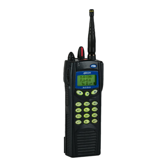
- Page 1 Operator’s Manual MM23772 Sept-05 P7200 Series Portable Radios...
- Page 2 M/A-COM, Inc., at any time and without notice. Such changes will be incorporated into new editions of this manual. No part of this manual may be reproduced or transmitted in any form or by any means, electronic or mechanical, including photocopying and recording, for any purpose, without the express written permission of M/A-COM, Inc.
-
Page 3: Table Of Contents
TABLE OF CONTENTS Page SAFETY TRAINING INFORMATION..........4 SAFETY CONVENTIONS ............... 6 OPERATING TIPS ................7 BATTERIES ..................9 SCOPE ..................... 12 INTRODUCTION................13 OPTIONS AND ACCESSORIES............ 14 USER INTERFACE................. 16 OPENSKY OPERATION..............26 BASIC OPERATION ..............28 TRUNKED OPERATION ............... 39 PROJECT 25 (P25) CONVENTIONAL OPERATION .... -
Page 4: Safety Training Information
Population” in an uncontrolled environment. The P7200 portable radio has been tested and complies with the FCC RF exposure limits for “Occupational Use Only.” In addition, this M/A-COM radio complies with the following Standards and Guidelines with regard to RF... - Page 5 FCC RF exposure limits of this radio. ELECTROMAGNETIC INTERFERENCE/COMPATIBILITY During transmissions, this M/A-COM radio generates RF energy that can possibly cause interference with other devices or systems. To avoid such interference, turn off the radio in areas where signs are posted to do so. DO NOT operate the transmitter in areas that are sensitive to electromagnetic radiation such as hospitals, aircraft, and blasting sites.
-
Page 6: Safety Conventions
M/A-COM, Inc. assumes no liability for the customer’s failure to comply with these standards. The WARNING symbol calls attention to a procedure, practice, or the like, which, if not correctly performed or adhered to, could result in personal injury. -
Page 7: Operating Tips
OPERATING TIPS Antenna location and condition are important when operating a portable radio. Operating the radio in low lying areas or terrain, under power lines or bridges, inside of a vehicle or in a metal framed building can severely reduce the range of the unit. - Page 8 Use only the supplied or approved antenna. Unauthorized antennas, modifications or attachments could cause damage to the radio unit and may violate FCC regulations. (Refer to Table WARNING Electronic Devices RF energy from portable radios may affect some electronic equipment. Most modern electronic equipment in cars, hospitals, homes, etc.
-
Page 9: Batteries
If memory is suspected, then it can be easily canceled by charging and discharging the problem battery two or three times. The battery should be charged using a M/A-COM rapid charger and discharged on the radio until low battery is indicated. - Page 10 BATTERY DISPOSAL Nickel Cadmium Battery At the end of its useful life, under various state and local laws, it may be illegal to dispose of Nickel Cadmium batteries into the municipal waste stream. Check with local solid waste officials for recycling options and proper disposal.
- Page 11 1. Align the tab on the top of the battery pack with the slot at the top of the battery cavity. 2. Push the battery pack down to attach the battery to the radio. 3. Verify that the battery pack is properly latched to the radio. Figure 2: Attaching the Battery Pack...
-
Page 12: Scope
SCOPE This manual will first introduce the user to the P7200 product line in general, identifying Regulatory and Safety requirements, Options and Accessories, the user interface, and other common components in the first few sections of the manual. The balance of this manual will then be devoted to functionality. It is not the intent of this manual to cover all modes of operation. -
Page 13: Introduction
INTRODUCTION The P7200 series radios are dual-band multi-mode portable radios. The dual- band (700/800 MHz) P7200 portable radio delivers end-to-end encrypted digital voice and IP data communications. It is designed to support multiple operating modes including: • ® OpenSky Trunked mode •... -
Page 14: Options And Accessories
OPTIONS AND ACCESSORIES Table 2 lists the Options and Accessories tested for use with the P7200 series portable radios. Refer to the maintenance manual or to M/A-COM’s Products and Services Catalog for a complete list of options and accessories, including those items that do not adversely affect the RF energy exposure. - Page 15 DESCRIPTION PART NUMBER Speaker Mic, Ruggedized <IS> KRY 101 1617/383 Speaker Mic, Antenna Version, Ruggedized KRY 101 1617/384 Speaker Mic, Ruggedized, Charger Comp., <IS> KRY 101 1617/385 Speaker Mic, Ant. Version, Ruggedized, Charger Comp <IS> KRY 101 1617/387 Metal Belt Clip KRY 101 1647/1 Belt Loop with Swivel KRY 101 1609/1...
-
Page 16: User Interface
USER INTERFACE Figure 3: Top View Figure 4: Side View... - Page 17 Figure 5: System Model...
- Page 18 Figure 6: Scan Model...
- Page 19 CONTROLS The radio features two rotary control knobs and an emergency button mounted on the top of the radio. Push-To-Talk, option, and monitor buttons are mounted on the side. The front mounted keypad has six buttons on the P7250 Scan model and 15 buttons on the P7270 System Radio. The P7230 Select model radio has no front keypad.
- Page 20 Keypad The keys on the Keypad have special functions and are labeled using a symbol or abbreviated word describing its primary function. Numeric entry is a secondary function of the keys. Each key is described in the following subsections. Figure 7: Scan Radio Front Panel FUNCTION Primary Function: Allows the user to select system, groups,...
- Page 21 Figure 8: System Radio Front Panel FUNCTION Same as Scan Model Same as Scan Model Selects a specific system. If the rotary knob is used to select the system and more than 16 systems are programmed in the radio, the key is used to select additional banks (groupings) of systems.
- Page 22 FUNCTION Deletes selected groups or channels of the currently selected system from the Scan list. Places telephone interconnect calls. Initiates individual calls. DISPLAY The P7200 display is made up of 3 lines. Lines 1 and 2 contain twelve alphanumeric character blocks each. The 3rd line also contains twelve blocks, each used primarily to display radio status icons.
- Page 23 Table 3: Display Descriptions Steady – “Busy” transmitting or receiving, Network connectivity Flashing – call queued Steady – Special call mode (individual or telephone) Steady – Stealth mode is enabled (all tones and other displays are off, voice is still heard). Steady –...
- Page 24 Figure 12: Tri-Color LED Tri-Color LED The Tri-Color LED changes color to indicate radio status and is visible from both the front and top of the radio (see Figure 12). The three colors of the LED and the status they represent are: Green: Receiving Red: Unencrypted transmission...
- Page 25 Table 4: Alert Tones NAME TONE DESCRIPTION Call one short mid- OK to talk after pressing the push-to-talk Originate pitched button Call one high-pitched Call queued for processing Queued Autokey one mid-pitched Queued call received channel assignment System three low-pitched System busy or unable to complete call Busy Call Denied (T)
-
Page 26: Opensky Operation
OPENSKY OPERATION Once an OpenSky system has been selected from the available systems on your P7200 series portable radio, the characteristics described in the following sections will govern operation. PERSONALITY As illustrated in Figure 13, a personality defines the profiles and talk groups available to the user. - Page 27 Talk Groups A talk group represents a set of users that regularly need to communicate with one another. There can be any number of authorized users assigned to a talk group. Talk groups are established and organized by the OpenSky network administrator.
-
Page 28: Basic Operation
BASIC OPERATION TURNING ON THE RADIO 1. Power ON the radio by rotating the POWER ON-OFF/VOLUME knob clockwise. A short alert signal (if enabled through programming) indicates the radio is ready to use. Refer to Figure 3 for location of the POWER ON-OFF/VOLUME KNOB. - Page 29 GROUP SELECTION Method 1 (System Model) 1. Press to access group list. 2. Press to scroll through the list of groups or the numeric key mapped to the desired group list. 3. Press to select desired group. The radio will move to the selected group.
- Page 30 Press twice to add as a Priority 2 group. Press three times to add as a Priority 1 group. 5. Press to re-start scanning. NUISANCE DELETE (SYSTEM MODEL) A channel can temporarily be deleted from the scan list if it is not the currently selected channel.
- Page 31 4. Press the PTT and will reappear. 5. Release PTT when the transmission is complete. LOCKING/UNLOCKING KEYPAD 1. Press button. 2. Within 1 second, press the Option button on the side of the radio. HIGH/LOW POWER ADJUSTMENT Transmit power adjustment is possible if enabled through programming. Within conventional systems, transmit power is adjustable on a per channel basis.
- Page 32 Figure 14: Menu Display 3. The radio will continue to receive and transmit normally while in the menu function. 4. To scroll through the menu options use the keys. When the required menu item has been found align the cursor with the option then press to select it.
- Page 33 4. The menu item's parameter setting shown in the display can now be changed by using 5. Once the desired setting is reached press to store the value and return the menu option selection level. For menu items that display radio information pressing will scroll through a list of informational displays.
- Page 34 RAM Size FLSH SIZ Flash Size RF BAND Frequency Band HSD RATE Data Transfer Rate PRS VER Software Version DSP_ _RAM DSP Software Version FLSH - VER FLASH Software r - released, 01A - revision state M/A-COM Copyright (C) – 2004...
- Page 35 Figure 17: Information Display DIGITAL VOICE OPERATION Digital voice programmed systems have three (3) different voice modes: clear (analog), digital, and private (encrypted). The voice modes are programmed on a per-group basis within each trunked system and on a per-channel basis within each conventional system.
- Page 36 Private Mode The Private Mode allows the radio to transmit encrypted messages and receive clear or private transmissions. The radio transmits private if the group/channel is programmed for private operation and forced operation is pre-programmed. If autoselect operation is pre-programmed and the radio is in the Private Mode, the radio transmits in the mode of the received call if the hang time is active.
- Page 37 Group/Channel Encryption Key Figure 19: Group/Channel Encryption Key Display Key Zero All cryptographic keys can be zeroed (erased from radio memory) by pressing the MONITOR/CLEAR button and while still pressing this button, press and hold the OPTION button. Press both buttons for 2 seconds. A series of beeps will begin at the start of the 2 second period and then switch to a solid tone KEY ZERO after the keys have been zeroed.
- Page 38 If a group or channel is not programmed for Private Mode operation, PVT DIS will be displayed if an attempt is made to enable private transmit mode. It is not possible to operate on this group/channel in Private Mode. NO KEY# If the radio does not have the correct encryption key loaded, will be displayed and the call will not be transmitted.
-
Page 39: Trunked Operation
TRUNKED OPERATION SCANNING TRUNKED GROUPS Groups that have been previously added to the scan list on a per system basis may be scanned. Each system's group scan list is retained in memory when the radio is powered OFF or when the battery pack is removed. The following procedures outline scan operations for trunked groups. - Page 40 4. Press the key a second time to set the group to Priority 2. A displayed on line three. Press a third time to set the group to Priority 1. A is displayed on line three. The priority level section sequence only advances the group to the next high priority level and stops at priority level 1.
- Page 41 Press a third time to set the group to Priority 1. A is displayed on line three. The priority level selection sequence only advances the group to next higher priority level and stops at priority level 1. To select a lower priority level, the group must be deleted from the scan list and then added back to the scan list.
- Page 42 ON when the radio is powered ON. Wide Area System Scanning The P7200 series radios can be programmed for Wide Area System Scan operation for roaming across mobile systems. Upon the loss of the currently selected system's control channel, radios can be programmed to automatically scan the control channels of other systems.
- Page 43 When ProScan is Enabled The radio monitors the priority system and will switch to the priority system if the criteria defined by the controls in the ProScan Options dialog box are met. If ProScan is enabled, the rate at which the radio will scan for the priority system is defined by the System Sample Time control, located in the ProScan Options dialog box.
- Page 44 Receiving an Emergency Call When receiving an Emergency Call on the selected group and system, an alert *RXEMER* beep is heard and is displayed. The message flashes in the display on line two until the emergency condition is cleared. Declaring an Emergency Call To send an emergency call to a selected system and group (or on an optionally pre-programmed group), proceed as follows: 1.
- Page 45 If a response is made by pressing the PTT to the call prior to the programmed call-back time-out, the call will automatically be directed to the originating unit. If a response is not made before the call-back time-out, the radio will *WHC* return to normal receive display, and will appear on the first line of...
- Page 46 Sending an Individual Call (Trunked Mode Only) Pre-Stored Individual Calls The following procedures describe how to initiate and complete a Pre-Stored Individual Call. System Model 1. To select a pre-stored individual phone number, enter the individual call mode using the key.
- Page 47 Call Storage Lists There are two lists available for call storage in the P7200 series radios, the calls received list (1 - 10) and the personality list (1 - 99 as defined by the user). When the individual call mode is entered by pressing , the calls received list is available.
- Page 48 Sending a Telephone Interconnect Call (Trunked Mode Only) Pre-Stored Number Use the following procedures to initiate and complete a Telephone Interconnect call: 1. System Model: To select a previously stored phone number, press Use the keys to scroll through the list of stored numbers. Scan Model: To select a previously stored phone number, press .
- Page 49 2. If the phone number is not stored in the pre-stored list of phone numbers, but the phone number is known, it can be entered directly from the keypad. Start by pressing the . Then enter the required number from the keypad.
- Page 50 Press to enter the overdial select/entry mode and follow the selection mode rules to call up a stored number from the phone list. is displayed. Press PTT to send the overdial sequence once. If the number needs to be transmitted again it must be selected or entered again (this prevents unwanted numbers from being sent the next time the PTT button is pressed during the call).
- Page 51 4. Press and hold until the display changes indicating that the number has been stored. Repeat steps 1-4 above if the number stored in an entry location needs to be changed. STATUS/MESSAGE OPERATION Status operation permits the transmission of a pre-programmed status condition to the EDACS site.
- Page 52 PORTABLE DATA The P7200 series portable radios, when operating in the EDACS configuration, permit either voice or data calls to be transmitted or received. The radio can handle only one type of call at a time; however, either data or voice is selected transparently by the operator through normal usage of the radio.
- Page 53 Displays The following will be displayed during the various states of data mode of operation: TX DATA Appears on top line of display when the radio is transmitting a data call. RX DATA Appears on top line of display when the radio is receiving a data call.
- Page 54 • Emergency is declared by pressing the pre-programmed emergency button. • A group or system is changed. Scan Lockout Mode Following the transmission or reception of a data call, if scan is enabled, scanning will stop temporarily (two independent pre-programmed times; after a receive data call and after a transmit data call).
-
Page 55: Project 25 (P25) Conventional Operation
PROJECT 25 (P25) CONVENTIONAL OPERATION GROUP CALLS IN P25 MODE Transmitting a Group Call 1. Select the desired P25 system. (P25 icon will appear in display.) 2. Select the Talk Group/Conventional Channel. (Selected simultaneously using either the system/group/channel knob or the group key.) 3. - Page 56 Receiving an Individual Call The radio will unmute according to the squelch mode defined in the radio personality (monitor, normal, selective). 1. Select the desired P25 system and Talk Group/Channel or turn scan on and make sure the desired channel is in the scan list. 2.
- Page 57 Receiving an Emergency Group Call 1. Select the desired P25 System and Talk Group/Channel. 2. When the radio detects an incoming Emergency Group Call, the radio will sound an alert tone and “RXEMER” will appear in the display. 3. Voice or emergency transmissions will be heard at the receiving radio. 4.
-
Page 58: Operation Following Water Contact
OPERATION FOLLOWING WATER CONTACT If the P7200 model radio has been immersed in water or if the microphone air path or speaker grill become clogged with water, follow instructions under “Radio Microphone” and “Radio Speaker” sections to assure the highest quality transmitted and received messages. -
Page 59: Immersible P7200 Preventive Maintenance
Preventive Maintenance for Immersion-Rated Radios P7200 model radios with Immersion Option HTMR must be serviced by a service center authorized and certified by M/A-COM to perform the necessary tests to verify watertight integrity. As part of a thorough preventive CAUTION... - Page 60 TECHNICAL ASSISTANCE – IMMERSIBLE P7200 To preserve the watertight integrity of the P7200 portable radio, the radio must be serviced by a service center authorized and certified by M/A-COM to perform the necessary tests to verify the watertight integrity. Use one of the following methods to locate the nearest service center authorized to service the radios warranted under Option HTMR.
- Page 61 NOTES...
-
Page 62: Battery Warranty
BATTERY WARRANTY M/A-COM, Inc. (hereinafter "Seller") warrants to the original purchaser for use (hereinafter "Buyer") that nickel-cadmium and nickel-metal hydride batteries supplied by Seller shall be free from defects in material and workmanship, and shall conform to its published specifications for a period of twelve (12) months from the date of purchase. -
Page 63: Warranty
Equipment covered under Paragraph B.3 and B.4. To be eligible for no-charge labor, service must be performed at a M/A-COM factory, by an Authorized Service Center (ASC) or other Servicer approved for these purposes either at its place of business during normal business hours, for mobile or personal equipment, or at the Buyer’s location, for... - Page 64 M/A-COM Wireless Systems 221 Jefferson Ridge Parkway Lynchburg, Virginia 24501 (Outside USA, 434-385-2400) Toll Free 800-528-7711 www.macom-wireless.com Printed in U.S.A.
Need help?
Do you have a question about the P7200 series and is the answer not in the manual?
Questions and answers