Table of Contents
Advertisement
Quick Links
Advertisement
Table of Contents

Related Manuals for M/A-Com Orion


Summary of Contents for M/A-Com Orion
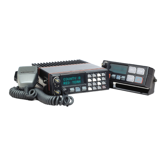
- Page 1 Installation Manual LBI-38901T Orion ™ Mobile Radio...
- Page 2 M/A-COM, Inc., at any time and without notice. Such changes will be incorporated into new editions of this manual. No part of this manual may be reproduced or transmitted in any form or by any means, electronic or mechanical, including photocopying and recording, for any purpose, without the express written permission of M/A-COM, Inc.
-
Page 3: Table Of Contents
TABLE OF CONTENTS Page INTRODUCTION ................4 UNPACKING AND CHECKING EQUIPMENT ......5 INSTALLATION (Single Control Unit) ......... 11 STEP 1 – PLAN THE INSTALLATION ........ 11 STEP 2 - LOCATE TOOLS REQUIRED........ 12 Vehicles Powered By Liquefied (Lp) Gas ......12 STEP 3 –... -
Page 4: Introduction
ORION UHF MOBILES The PC programmer automatically defaults the receiver oscillator shift to position No. 2. When field programming, the receive frequencies for Orion UHF mobiles, the oscillator shift must be programmed to position No. 1 or No. 3. Enter CAUTION... -
Page 5: Unpacking And Checking Equipment
UNPACKING AND CHECKING EQUIPMENT Carefully unpack the radio and identify each item in the shipping container as listed below. The available options for the Orion Mobile Radio are covered in Table 1. If damage has occurred to the equipment during shipment, file a claim with the carrier immediately. - Page 6 Figure 3: Option Cables...
- Page 7 At the time this manual was published, M/A-COM, Inc. was in the process of offering additional programming cables and replacing some of the accessory cables for the Orion mobile radio. This manual provides information on both the existing cable offerings and the replacement cables. The following...
- Page 8 The programming cables shown in Figure 5 do not require the TQ3370 interface box. The field programming cables shown in Figure 5 are ONLY compatible with the following accessory cables: NOTE CA101288V2, CA101288V4, CA101288V10 Programming Interface Cable, CA101287V2 CA101287V1 and Mobile Data Interface, Keyloading Interface CA101287V3 Figure 5: Programming/Interface Cables...
- Page 9 Table 1: Orion Mobile Radio Options And Accessories OPTION DESCRIPTION Z OPTIONS D2ZN1A Accessory Kit–Front Mount with Standard Option Cable D2ZN1B Accessory Kit–Front Mount with Extended Option Cable D2ZN1C Accessory Kit–Front Mount Euro with Standard Option Cable D2ZN1D Accessory Kit–Front Mount Euro with Extended Option Cable D2ZN1F Accessory Kit–Remote Mount with Standard Option Cable, 50W TX and below...
- Page 10 Programming Cable, Field (CA101287V1). Does not require TQ3370 TQ3370 Programming Interface Module Kit 110 VAC, only needed for 19B802554P15 TQ3370- Programming Interface Module Kit 220 VAC, only needed for 19B802554P15 TQ3377 Programming Cable for Orion (19B802554P15). Requires TQ3370 ™ ® ® TQ3385 ProVoice...
-
Page 11: Installation (Single Control Unit)
• safe and out of the way for passengers and auto mechanics M/A-COM, Inc. recommends the radio be installed by one of the many M/A- COM, Inc. Authorized Service Centers located throughout the United States. Experienced service centers can provide a proper radio installation and make any required final adjustments. -
Page 12: Step 2 - Locate Tools Required
STEP 2 - LOCATE TOOLS REQUIRED The equipment required for installing the Orion Mobile Radio is listed below: • Crimping tool for fuse holder • Electric drill for drilling mounting holes • Drills and circle cutters as follows: No. 31 (1/8”) drill No. -
Page 13: Step 3 - Install Cables
STEP 3 – INSTALL CABLES To ensure the feasibility of the planned cable routings, it is recommended that the cables be run before mounting the radio. The radio can be installed as a Front Mount, Remote Mount or Cassette Mount. The type of mount, the application, and the options to be installed should be considered when planning the cable runs. -
Page 14: Ignition Sense (All Applications)
3. Cut off 12-18″ from the red lead. Strip back the insulation approximately 3/8″ on each end of the wires. Insert the wire ends into the small openings at the end of each fuse holder section and crimp a fuse connector to each wire. - Page 15 • The radio, as shipped from the factory, has the "ignition sense" feature disabled. As such, the radio is powered ON or OFF as determined by the front panel ON/OFF/ VOLUME control only (assuming A+ and A- are connected). To enable "ignition sense"...
-
Page 16: Accessory Cable (Front Mount)
Accessory Cable (Front Mount) The basic accessory cable consists, at one end, the basic accessories connector (P3), the speaker connector (P2), and the ignition sense lead. At the other end, plug P1 connects to the Option/Remote Control connector (ORCC), which is mounted on the back of the radio. The EURO accessory cable contains the red and black leads of the power cable. - Page 17 Figure 9: Front Mount Basic Accessory Interconnections (EURO Models Only) Figure 10: Front Mount Extended Option Accessory Interconnections using 19B802554P2 (USA Models Only)
- Page 18 *(P5) Provides access for Programming/ Keyloading/ Mobile Data Figure 11: Front Mount Extended Option Accessory Interconnections using CA101288V2 (USA Models Only) Figure 12: Front Mount Extended Option Accessory Interconnections (EURO Models Only)
- Page 19 (19B802554, Sh.1, Rev. 23) Figure 13: USA Front Mount Standard Accessory Cable 19B802554P1...
- Page 20 (19B802554, Sh.9, Rev. 23) Figure 14: EURO Front Mount Standard Accessory Cable 19B802554P11...
- Page 21 (19B802554, Sh.2, Rev. 23) Figure 15: USA Front Mount Extended Option Accessory Cable 19B802554P2...
- Page 22 Figure 16: Front Mount Extended Option Accessory Cable CA101288V2...
- Page 23 (19B802554, Sh.10, Rev. 23) Figure 17: EURO Front Mount Extended Option Accessory Cable 19B802554P12...
-
Page 24: Accessory And Control Cable (Remote Mount)
Accessory and Control Cable (Remote Mount) The control cable connects the Control Unit (through the R1A) to the Radio Transceiver in remote applications. Plug P2, at one end, connects to the Remote Control Cable connector (RCCC) mounted on the back of the R1A. The Ignition Sense wire is also part of P2. - Page 25 Figure 18: Remote Mount Basic Accessory Interconnections (USA Models Only) Figure 19: Remote Mount Basic Accessory Interconnections (EURO Models Only) Figure 20: Remote Mount Extended Option Accessory Interconnections (USA Models Only)
- Page 26 *(P5) Provides access for Programming/Keyloading/Mobile Data Figure 21: Remote Mount Extended Option Accessory Interconnections using CA101288V4 (USA Models Only) Figure 22: Remote Mount Extended Option Accessory Interconnections (EURO Models Only)
- Page 27 (19B802554, Sh.5, Rev. 23) Figure 23: Remote Mount Standard Accessory Cable 19B802554P6...
- Page 28 (19B802554, Sh.6, Rev. 23) Figure 24: Remote Mount Extended Option Accessory Cable 19B802554P7...
- Page 29 (19B802554, Sh.3, Rev. 23) Figure 25: USA Remote Control Cable 19B802554P3...
- Page 30 (19B802554, Sh.4, Rev. 23) Figure 26: USA Remote Extended Option Control Cable 19B802554P4...
- Page 31 Figure 27: Remote Extended Option Control Cable CA101288V4...
- Page 32 (19B802554, Sh.11, Rev. 23) Figure 28: EURO Extended Options Remote Control Cable 19B802554P13...
- Page 33 (19B802554, Sh.12, Rev. 23) Figure 29: EURO Extended Options Remote Control Cable 19B802554P14...
-
Page 34: Step 4 - Mount Control Unit And Radio
STEP 4 – MOUNT CONTROL UNIT AND RADIO Control Unit Mounting (Remote Applications Only) 1. Use the bracket as a template and mark and drill the mounting holes. Be sure to leave enough room at the rear of the control unit for the cable connector. - Page 35 When mounting two DB-15 connectors to the control unit, mount one pigtail bracket on each side of the existing mounting hardware of the control unit. NOTE 1. Attach DB15 connector to the rectangular end of bracket with 2 pan head machine screws and washers.
- Page 36 5. Re-use the Orion mounting hardware to fasten the Pigtail Bracket to the side of the Orion. Make sure you use a flat washer under each screw (See Figure 33). 6. Before tightening Pigtail Bracket down, position the bracket up or down to suit the installation requirements.
-
Page 37: Radio Front Mount And Final Hook-Up
Radio Front Mount And Final Hook-Up Typically, the bracket shown in Figure 34 is used for Front Mount applications. The bracket can be mounted so that it is either above or below the radio as convenient. The bracket shown in Figure 30 can also be used for Remote Mount applications but is not recommended for 110 watt VHF radios or 100 watt UHF radios. -
Page 38: Radio Remote Mount And Final Hook-Up
Top Mount Bottom Mount Figure 34: Mounting Bracket Installation Radio Remote Mount and Final Hook-Up The bracket shown in Figure 35 is used for Remote Mounting (USA only). In some applications, the bracket shown in Figure 34 can also be used. The following instructions are for a Remote Mount installation using the bracket shown in Figure 35. - Page 39 7. Connect other end of the remote control cable to the remote control cable connector (RCCC) on the remote control unit. 8. Connect remote mount accessory cable connector P1 to the option connector (OPT) on control unit. Then, connect the speaker to connector P2 and accessory connector P3 to any options (hookswitch, etc.).
-
Page 40: Cassette Mounting (Euro Only)
Cassette Mounting (EURO Only) The cassette mounting assembly is designed to mount in a standard DIN space in the instrument panel or console. This mounting permits rapid insertion and removal of the radio unit from the vehicle. All connections are made through a quick disconnect connector at the rear of the cassette mounting assembly to the radio unit. - Page 41 b. Using the machine screws and flat washers provided with the handle assembly, attach the handle to the bottom of the radio. The two holes on the handle should align with the two holes on the radio created by step (A). Once installed, the rubber handle should rotate freely from over top of the radio to just out in front of the control unit (approximately 90 degrees).
- Page 42 9. With the handle assembly in the UNLOCKED position (out in front of the control unit), insert the radio into the cassette assembly. Slide the radio into the cassette assembly until the back of the radio meets the back of the cassette assembly. Caution should be used while engaging the radio in the cassette the first few times until the cabling in the cassette mount assembly has settled into its permanent location.
- Page 43 (19C852366, Sh.2, Rev.2) Figure 38: Cassette Assembly Schematic Diagram...
-
Page 44: Step 5 - Install Options And Accessories
STEP 5 - INSTALL OPTIONS AND ACCESSORIES Speaker D2LS1F The speaker kit includes the speaker, mounting bracket and connecting cable. Mount the speaker so it is directed to the operator but does not present a hazard in the event of an accident. The speaker can be mounted on the lower edge of the instrument panel, the firewall or above the windshield in some trucks. -
Page 45: Siren And Light
2. Add a jumper from pin 1 to pin 19. This modification to the SS2000 cable harness will disable the Orion’s capability to turn on and off the SS2000 from the front of the control head. The SS2000 will now be turned on and off strictly by its own ignition switch ®... - Page 46 PC board in the back half of the unit. To access these jumpers, the RIA must be removed from the control unit, as follows: 1. Disassemble the Orion control unit using steps given in LBI-38909, page 4, “Disassembly Procedures”.
-
Page 47: Installation (Dual Control Units)
Siren Light Controller Unit A Siren Light Connection Unit A Speaker Disable Multiple Radio Disable PROGRAM RADIO SETUP Mobile Options Push Button ORION OPTIONS Write Orion System Keypad File Enable (System control unit) Write Scan Keypad File Enable (Scan control unit) - Page 48 Figure 40: Step A Programming Diagram for Front Mount Dual Control Unit...
- Page 49 Siren Light Controller Unit A Siren Light Connection Unit A Speaker Disable Multiple Radio Disable PROGRAM RADIO SETUP Mobile Options Push Button ORION OPTIONS Write Orion System Keypad File Enable (System control unit) Write Scan Keypad File Enable (Scan control unit)
- Page 50 Figure 41: Step B Programming Diagram Front Mount Dual Control...
-
Page 51: Remote Mount Procedure 1
Siren Light Controller Unit A Siren Light Connection Unit A Speaker Disable Multiple Radio Disable PROGRAM RADIO SETUP Mobile Options Push Button ORION OPTIONS Write Orion System Keypad File Enable (System control unit Write Scan Keypad File Enable (Scan control unit) - Page 52 Figure 42: Step A Programming Diagram Remote Mount Dual Control...
- Page 53 Siren Light Controller Unit A Siren Light Connection Unit A Speaker Disable Multiple Radio Disable PROGRAM RADIO SETUP Mobile Options Push Button ORION OPTIONS Write Orion System Keypad File Enable (System control unit) Write Scan Keypad File Enable (Scan control unit)
- Page 54 Figure 43: Step B Programming Diagram Remote Mount Dual Control...
-
Page 55: Step 2 - Install Dual Control Units
STEP 2 – INSTALL DUAL CONTROL UNITS Front Mount The Dual Control Unit feature is configured such that only one Control Unit can be used for Extended Option accessories. Connect all Extended Option accessories through the Main Control Unit. 1. Referring to Figure 44 and Figure 45, run the Dual Control Cable (19B802554P9) between locations for the Radio Unit and Auxiliary Control Unit. - Page 56 7. Install a relay (19A149299P1) from the kits supplied at a location near the leads from each speaker. For mounting, use the #8 x 3/4” sheet metal screw and nut plate supplied with each kit. 8. At a convenient point, cut one of the wires in each of the 2-wire speaker cables, spread the leads, and strip the ends.
- Page 57 Figure 44: Dual Control Unit Front Mount Installation Configuration using 19B802554P1 or P2...
-
Page 58: Remote Mount
Figure 45: Dual Control Unit Front Mount Installation Configuration using CA101288V2 Remote Mount 1. Referring to Figure 46 and Figure run the Remote Control Cable (19B802554P3, 19B802554P4 or CA101288V4) between locations for the Radio unit and Main Control unit. 2. Run the Dual Control Cable (19B802554P9) between locations for the radio unit and Auxiliary Control unit. - Page 59 5. After installing the Auxiliary Control Unit in the normal fashion, connect the Dual Control Cable (P1) to the Auxiliary Control Unit and tighten the jackscrews. 6. Connect the accessory cable (19B802554P6) to the Auxiliary Control Unit. Connect either the accessory cable (19B802554P6) or the extended option accessory cable (19B802554P7) to the Main Control Unit as appropriate.
- Page 60 13. For Each Relay: Connect a #18 AWG black wire between the relay, Pin 85 and accessory cable P3-1 (labeled “OUT2” on schematic diagrams in the service manual). Use a ¼” tab receptacle on the relay side and a mating Molex connector and pins on the accessory cable side. Connect the mating Molex connector to the accessory cable P3 when finished.
- Page 61 Figure 47: Dual Control Unit Remote Mount Installation Configuration using CA101288V4...
- Page 62 (19B802554, Sh.7, Rev. 23) Figure 48: Remote Mount Dual Control Cable 19B802554P9...
-
Page 63: Dual Radio Units
Connect extended options to the Master radio unit only. Both the Orion Master and Orion Slave mobiles must be programmed with the same Group version of Flash code. The Group version must be G30 or later. Failure to do so may... -
Page 64: Master Radio Programming
Enable for Master radio only Receive Only Enable for Master radio only MuRPS Disable for Master radio only PROGRAM RADIO SETUP Mobile Options Push Button ORION OPTIONS Write Orion System Keypad File Enable (System control unit) Write Scan Keypad File Enable (Scan control unit) - Page 65 Figure 49: MASTER Radio Field Programming Configuration (Dual Radio)
- Page 66 Figure 50: SLAVE Radio Field Programming Configuration (Dual Radio)
-
Page 67: Step 2 - Install Cables/Equipment
STEP 2 – INSTALL CABLES/EQUIPMENT Front Mount Plan the mounting locations of the two radio units. Note that the maximum cable length allowed between the two radios is two meters. Referring to Figure 53 and Figure 54, run Dual Radio cable (19B802554P10 or CA101288V10) between locations for Master and Slave radio units. - Page 68 19B802554P2 EXTENDED OPTIONS (OPTIONAL) Figure 51: Orion Dual Radio Front Mount Installation Configuration *Provides access for Programming/ Keyloading/ Mobile Data **(A + B) Optional Extension Cable for Remote Dual Radio (CA101288V30) provides access flexibility for Programming and Keyloading to the second radio of a dual configuration.
-
Page 69: Remote Mount
Remote Mount 1. Plan the mounting locations of the two radio units. Note that the maximum cable length allowed between the two radios is two meters. Referring to Figure 53 and Figure 54, run Dual Radio cable (19B802554P10 or CA101288V10) between locations for Master and Slave radio units. - Page 70 19B802554P7 EXTENDED OPTIONS (OPTIONAL Figure 53: Orion Dual Radio Remote Mount Installation Configuration *Provides access for Programming/ Keyloading/ Mobile Data **(A + B) Optional Extension Cable for Remote Dual Radio (CA101288V30) provides access flexibility for Programming and Keyloading to the second radio of a dual configuration.
- Page 71 (19B802554, Sh.8, Rev. 23) Figure 55: Dual Radio Control Cable 19B802554P10...
- Page 72 Figure 56: Dual Radio Control Cable CA101288V10...
- Page 73 Figure 57: Programming Interface Cable CA101287V1...
-
Page 74: Keyloading The Radio
Keyloading the Radio 1. Attach the Keyloading Interface Cables’, Male DB-15, connector to connector P5 of CA101288V2, V4 or V10 and the Male RJ-45 to the Keyloader. 2. Turn on power of radio to be keyloaded from the control unit. 3. -
Page 75: Keyloading A Dual Radio
Keyloading a Dual Radio 1. Attach the Keyloading Interface Cables’ DB-15 to the radio to be keyloaded through connector P5, and the RJ-45 connector to the Keyloader. 2. Select the radio to be keyloaded from the control unit by accessing the RADIO function via the radio’s menu. - Page 76 Figure 60: Shop Programming Cable CA101288V15...
- Page 77 Figure 61: Extension Cable for Dual Remote Radio CA101288V30...
-
Page 78: Technical Assistance
TECHNICAL ASSISTANCE M/A-COM’s Technical Assistance Center (TAC) resources are available to help you with the overall system’s operation, maintenance, and product support. TAC is your point of contact when you need technical questions answered. For more information about technical assistance services, contact... - Page 79 NOTES...
- Page 80 M/A-COM Wireless Systems 221 Jefferson Ridge Parkway Lynchburg, Virginia 24501 (Outside USA, 434-385-2400) Toll Free 800-528-7711 www.macom-wireless.com Printed in U.S.A.
Need help?
Do you have a question about the Orion and is the answer not in the manual?
Questions and answers