M/A-Com M7100 IP Operator's Manual
Desktop station; wall mount station
Hide thumbs
Also See for M7100 IP:
- Operator's manual (109 pages) ,
- Installation manual (101 pages) ,
- Installation and safety manual (72 pages)
Table of Contents
Advertisement
Quick Links
Advertisement
Table of Contents

Related Manuals for M/A-Com M7100 IP


Summary of Contents for M/A-Com M7100 IP
- Page 1 Operator’s Manual MM21853 Mar-05 M7100 Desktop Station Wall Mount Station...
- Page 2 M/A-COM, Inc., at any time and without notice. Such changes will be incorporated into new editions of this manual. No part of this...
-
Page 3: Table Of Contents
TABLE OF CONTENTS Page SAFETY INFORMATION ............4 INTRODUCTION................ 5 STANDARD FEATURES........... 5 OPTIONS................6 2.2.1 Remote/Intercom Option..........6 2.2.2 VU Meter/Clock Option..........6 2.2.3 Remote/Intercom/VU Meter/Clock Option....7 2.2.4 Wall Mount Station Control Panel........ 7 CONTROLS AND INDICATORS ..........8 VOLUME CONTROL............ -
Page 4: Safety Information
M/A-COM, Inc. assumes no liability for the customer’s failure to comply with these standards. The WARNING symbol calls attention to a procedure, practice, or the like, which, if not correctly performed or adhered to, could result in personal injury. -
Page 5: Introduction
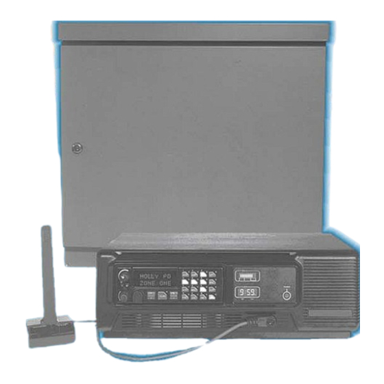
2 INTRODUCTION Figure 2-1: Desktop Station Front Panel with VU Meter/Clock ® The M/A-COM M7100 Desktop Station is shown in Figure 2-1 This Station combines the flexibility of a Local Control Station with a Remote Control Station in one desktop package. -
Page 6: Options
OPTIONS The standard Desktop Station can be configured in several different ways including Remote/Intercom controls, and/or VU (Volume Unit) Meter/Clock display. 2.2.1 Remote/Intercom Option Desktop Stations equipped with the Remote/Intercom option (see Figure 2-3) permits the use of Remote Controllers. Local and Remote Station control is provided for station functions such as Transmit, Receive and Intercom Audio, PTT (Press-To-Talk) Control, and Channel Guard Monitor. -
Page 7: Remote/Intercom/Vu Meter/Clock Option
2.2.3 Remote/Intercom/VU Meter/Clock Option Desktop Stations with the Remote/Intercom/VU Meter/Clock option have the full compliment of controls described in sections 2.2.1 and 2.2.2 (see Figure 2-5). Figure 2-5: Remote/Intercom/VU Meter/Clock Option Control Panel 2.2.4 Wall Mount Station Control Panel Wall Mount Stations include a basic control panel located inside the housing (see Figure 2-6). -
Page 8: Controls And Indicators
3 CONTROLS AND INDICATORS 3.1 VOLUME CONTROL The radio volume control is used for Desktop Stations with the Standard Control Panel (Non-Remote Control Stations). The volume control on the radio must be variable only for the Local Control Stations. Desktop Stations equipped with the optional Remote Control Panel are equipped with a separate volume control located on the Station Control Panel. -
Page 9: Station Operation
4 STATION OPERATION 4.1 BASIC STATION Turn on the main ON/OFF power switch located on the rear of the Station housing. The front panel LED illuminates, indicating that the power supply to the cooling fan is on. Fan operation is temperature controlled. 4.2 REMOTE/INTERCOM These switches control the audio paths between remote and local microphones, the radio, and remote and local speakers. - Page 10 This configuration offers intercom REMOTE INTERCOM service only. Neither the Desktop nor the Remote Mics can key the radio transmitter. The radio receiver's audio can be heard on the Station speaker, but not on the Remote speaker. A message from the Desktop Mic is heard on the Remote speaker. An intercom message from the Remote Mic can be heard on the Desktop speaker, but only if the Desktop Mic is not active.
-
Page 11: Clock
4.3 CLOCK The VU Meter bar graphic display is inactive during time setting mode. NOTE 4.3.1 12/24 hour mode Below the clock display, there are two switches: SW1 and SW2. 1. Press SW1 for approximately 1 second. "12__" or "24__" will appear in the display. -
Page 12: Tone Remote Controller
The Controller is capable of selecting up to five software defined radio systems, group, or special call combinations. The presets are programmed into the radio using M/A-COM ProGrammer™ software. The Controller and Desktop Station can operate as an intercom by setting the Intercom switch to ON or M. -
Page 13: Local/Remote Controls Summary
5 LOCAL/REMOTE CONTROLS SUMMARY ⎯⎯> Remote Mic Radio Xmtr REMOTE INTERCOM ⎯⎯> Remote Mic Station Spkr ⎯/⎯> Desktop Mic Radio Xmtr Remote Spkr if Rx is muted; otherwise, ⎯⎯> Desktop Mic Rx⎯⎯>Remote Spkr & Station Spkr Station Spkr & Remote ⎯⎯>... -
Page 14: Warranty
Equipment covered under Paragraph B.3 and B.4. To be eligible for no-charge labor, service must be performed at a M/A-COM factory, by an Authorized Service Center (ASC) or other Servicer approved for these purposes either at its place of business during normal business hours, for mobile or personal equipment, or at the Buyer’s location, for fixed location equipment. - Page 15 NOTES...
- Page 16 M/A-COM Wireless Systems 221 Jefferson Ridge Parkway Lynchburg, Virginia 24501 (Outside USA, 434-385-2400) Toll Free 800-528-7711 www.macom-wireless.com Printed in U.S.A.
Need help?
Do you have a question about the M7100 IP and is the answer not in the manual?
Questions and answers