Sign In
Upload
Manuals
Brands
M/A-Com Manuals
Portable Radio
M/A-COm P5200 Series
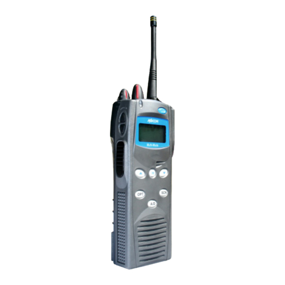
User Manuals: M/A-Com M/A-COm P5200 Series Accessories
Manuals and User Guides for M/A-Com M/A-COm P5200 Series Accessories. We have
1
M/A-Com M/A-COm P5200 Series Accessories manual available for free PDF download: Operator's Manual
M/A-Com M/A-COm P5200 Series Operator's Manual (122 pages)
Brand:
M/A-Com
| Category:
Portable Radio
| Size: 3 MB
Table of Contents
Table of Contents
3
1 Safety Conventions
10
2 Safety Training Information
11
Rf Exposure Guidelines
11
Electromagnetic Interference/Compatibility
12
Table 2-1: RF Exposure Compliance Testing Distances
12
3 Operating Tips
13
Efficient Radio Operation
13
Antenna Care and Replacement
13
Electronic Devices
13
Aircraft
14
Electric Blasting Caps
14
Potentially Explosive Atmospheres
14
4 Batteries
15
Conditioning Battery Packs
15
Conditioning Nimh Battery Packs
15
Conditioning Nicd Battery Packs
15
Additional Information
15
Charging Battery Packs
16
Charging Guidelines
16
Battery Pack Usage
16
Usage Guidelines
16
Change the Battery Pack
17
Remove the Battery Pack
17
Attach the Battery Pack
17
Figure 4-1: Removing the Battery Pack
17
Figure 4-2: Attaching the Battery Pack
17
Battery Disposal
18
5 Introduction
19
Figure 5-1: P7230 Select Model Radio
20
Figure 5-2: P7250 and P5250 Scan Models
20
Figure 5-3: P7270 System Model
21
Universal Device Connector (Udc)
21
Water Resistance (P7200 Only)
21
6 Options and Accessories
22
Table 6-1: Options and Accessories
22
7 Change Operating Mode
24
Change from Otp Mode
24
Change to Otp Mode
24
8 Opensky Operation
25
Power On/Off and Volume Control
25
Power ON/OFF
25
Volume Control
25
Controls
25
Figure 8-1: Top and Side View
25
Buttons and Knobs
26
Keypad (P7250, P5250, and P7270)
27
Table 8-1: Keypad Functions
27
Display
28
Radio Status Icons
28
Figure 8-2: Radio Display
28
Table 8-2: Status Icons Descriptions
28
Tri-Color Led
29
Log in to the Network
29
Figure 8-3: Tri-Color LED
29
Log off the Network
30
Personality
30
Profiles
30
Talk Groups
30
Figure 8-4: Personality Structure Example
30
Opensky Display Overview
31
Display's Top Line
31
Display's Second Line
31
Dwell Display
31
Alert Tones
32
Table 8-3: Alert Tones
32
Basic Menu Structure
33
Table 8-4: Basic P7200 and P5200 Opensky Menu Structure
33
Error Messages
35
Keypad
37
Keypad Function Commands (P7270 Only)
37
Table 8-5: Keypad Function Commands
37
Quick Buttons (P7270 Only)
38
LOCK/UNLOCK the KEYPAD
38
Dual-Tone Multi-Frequency (P7270 Only)
38
Table 8-6: Quick Buttons
38
Change the Active Profile
39
Change the Selected Talk Group
39
Adjust Display and Button Backlight Brightness
39
Stealth Mode
39
Enable Stealth Mode
39
Disable Stealth Mode
39
Adjust Side Tone Audio Level
40
Change Operating Mode
40
Receive and Transmit Voice Calls
40
Receive a Voice Call
40
Transmit a Voice Call
41
Adjust Audio Treble Level
41
Talk Group Lock out
41
Lock out a Talk Group
42
Unlock a Talk Group
42
Scanning
42
Select Scan Modes
42
Change Active Scan Mode
43
Table 8-7: Scan Modes
43
Scan Priority
44
Make Selective Calls
44
Manually Dialing a Selective Call (P7270 Only)
45
Selective Call Using Speed Dial
45
Table 8-8: Status of Selective Call
45
Accept a Selective Call
46
Reject a Selective Call
46
Terminate a Selective Call
46
Selective Alerts
46
Define Messages
46
Send a Message
47
Table 8-9: Status of Selective Alert Messages
47
Receive a Message
48
Delete a Selective Alert Message
48
Interconnect Calls (P7270 Only)
48
Make an Interconnect Call
48
Receive an Interconnect Call
49
Emergency Communications
49
Declare an Emergency Call or Alert
49
Table 8-10: Emergency Calls Vs. Emergency Alerts
49
Receive an Emergency Call
50
Dismiss an Emergency
50
Clear an Emergency
50
Opensky Encryption (P7200 Only)
51
Automatic Encryption
51
Manual Encryption (P7270 Only)
51
Dynamic Regrouping
52
Gps Coordinates
52
V-Tac Functions
52
Extended Coverage Modes ("XCOV" and "XCOV-TG")
52
Change between Extended Coverage Modes
53
Use the XCOV Mode
53
Use the XCOV-TG Mode
54
Use the Scene-Of-Incident Mode
55
Table 8-11: Band Definitions
56
9 Edacs and P25 Trunked Operation
57
Turn on the Radio
57
Controls
57
Figure 9-1: Top and Side View
57
Buttons and Knobs
58
Figure 9-2: P7250 and P5250 Radio Front Panel
59
Keypad (P7250, P5250, and P7270)
59
Table 9-1: P7250 and P5250 Keypad Functions
59
Figure 9-3: P7270 Radio Front Panel
60
Table 9-2: P7270 Keypad Functions
60
Display
61
Figure 9-4: Radio Display
61
Radio Status Icons
62
Table 9-3: Display Descriptions
62
Tri-Color Led
63
Status Messages
63
Figure 9-5: Tri-Color LED
63
Error Messages
64
Alert Tones
64
Table 9-4: Alert Tones
64
System Selection
65
Group/Channel Selection
65
Modify Scan List
66
P7270 Model
66
P7250 and P5250 Models
66
Nuisance Delete (P7270 Model)
67
Backlight On/Off
67
Contrast Adjust
67
Declare an Emergency
67
Lock/Unlock the Keypad
67
High/Low Power Adjustment
68
Using the Menu Button
68
Using the Pre-Programmed Option Button
68
Menu
68
Figure 9-6: Menu Display
68
Figure 9-7: Backlight Menu Display
69
Menu Item Selection Process
69
Table 9-5: Menu Item Information
69
Table 9-6: Information Display
70
Digital Voice Operation
71
Clear Mode
71
Digital Mode
71
Private Mode (P7200 Only)
71
Private Operation (P7200 Only)
72
Figure 9-8: System Encryption Key Display
72
Figure 9-9: Group/Channel Encryption Key Display
72
Scan Trunked Groups
73
Turn Scan on and off
73
Table 9-7: Transmit/Receive Mode Compatibility for Digital Voice Operation
73
Add Groups to a Scan List
74
Delete Groups from a Scan List
75
Nuisance Delete
76
Scan Trunked Systems
76
Wide Area System Scanning
76
Priority System Scan
76
Proscan
77
Emergency Operation
77
Receive an Emergency Call
77
Declare an Emergency Call
77
Clear an Emergency Call
77
Individual Calls
78
Receive and Respond to an Individual Call
78
Figure 9-10: Calls Received Lists
78
Send an Individual Call
79
Call Storage Lists
79
Figure 9-11: WHC Individual Call Display
79
Telephone Interconnect Calls
80
Receive a Telephone Interconnect Call
80
Send a Telephone Interconnect Call
80
Figure 9-12: Calls Received and Personality Lists
80
Dual-Tone Multi-Frequency: Overdial/Conventional Mode
81
Programmable Entries
82
Pre-Store Individual and Telephone Interconnect Calls from the Keypad
82
Status/Message Operation
82
Status Operation
82
Message Operation
83
Dynamic Regroup Operation
83
Emergency Operation
83
Macro Key Operation
83
Portable Data
84
Displays
84
DATA off Operation
84
DATA on Operation
84
Exit Data Calls
84
Scan Lockout Mode
85
Data Lockout Mode
85
Page (P25 Trunked Only)
85
10 Project 25 (P25) Conventional Operation
86
Turn on the Radio
86
Controls
86
Figure 10-1: Top and Side View
86
Buttons and Knobs
87
Figure 10-2: P7250 and P5250 Radio Front Panel
88
Keypad (P7250, P5250, and P7270)
88
Table 10-1: P7250 and P5250 Keypad Functions
88
Figure 10-3: P7270 "System" Radio Front Panel
89
Table 10-2: P7270 Keypad Functions
89
Display
90
Figure 10-4: Radio Display
90
Radio Status Icons
91
Table 10-3: Display Descriptions
91
Tri-Color Led
92
Status Messages
92
Figure 10-5: Tri-Color LED
92
Error Messages
93
Alert Tones
93
System Selection
93
Table 10-4: Alert Tones
93
Group/Channel Selection
94
Modify Scan List
94
P7270 System Model
94
P7250 and P5250 Model
95
Nuisance Delete (P7270 Model)
95
Backlight On/Off
95
Contrast Adjust
95
Declar an Emergency
96
Lock/Unlock Keypad
96
High/Low Power Adjustment
96
Using the Menu Button
96
Using the Pre-Programmed Option Button
96
Menu
96
Menu Item Selection Process
97
Figure 10-6: Menu Display
97
Figure 10-7: Backlight Menu Display
97
Table 10-5: Menu Item Information
98
Digital Voice Operation
99
Clear Mode
99
Digital Mode
99
Table 10-6: Information Display
99
Private Mode (P7200 Only)
100
Figure 10-8: System Encryption Key Display
100
Figure 10-9: Group/Channel Encryption Key Display
100
Private Operation (P7200 Only)
101
Table 10-7: Transmit/Receive Mode Compatibility for Digital Voice Operation
101
Group Calls in P25 Mode
102
Transmit a Group Call
102
Receive a Group Call
102
Individual Calls in P25 Mode
102
Transmit an Individual Call
102
Receive an Individual Call
102
Emergency Group Calls in P25 Mode
103
Declare an Emergency Group Call
103
Receive an Emergency Group Call
103
11 Conventional Operation
104
Controls
104
Figure 11-1: Top and Side View
104
Buttons and Knobs
105
Figure 11-2: P7250 and P5250 Radio Front Panel
106
Keypad (P7250, P5250, and P7270)
106
Table 11-1: P7250 and P5250 Keypad Functions
106
Table 11-2: P7270 Keypad Functions
107
Display
108
Radio Status Icons
108
Table 11-3: Display Descriptions
108
Tri-Color Led
109
Status Messages
109
Error Messages
109
Alert Tones
110
Turn on the Radio
110
System Selection
110
Table 11-4: Alert Tones
110
Channel Selection
111
Modify Scan List
111
P7270 Model
111
P7250 and P5250 Model
112
Nuisance Delete (P7270 Model)
112
Backlight On/Off
112
Contrast Adjust
112
Declare an Emergency
112
Lock/Unlock Keypad
113
High/Low Power Adjustment
113
Using the Menu Button
113
Using the Pre-Programmed Option Button
113
Menu
113
Menu Item Selection Process
114
Table 11-5: Menu Item Information
115
Receive a Call
116
Transmit a Call
116
Table 11-6: Information Display
116
12 Technical Assistance
117
Immersible P7200
117
13 Basic Troubleshooting
118
Table 13-1: Troubleshooting
118
Battery Warranty
119
Advertisement
Advertisement
Related Products
M/A-Com M/A-COM P7200 Series
M/A-Com P5100 Series
M/A-Com P7100IP
M/A-Com LPE-200
M/A-Com tyco JAGUAR 725P
M/A-Com tyco JAGUAR 725Pi
M/A-Com Categories
Radio
Portable Radio
Amplifier
Receiver
Power Supply
More M/A-Com Manuals
Login
Sign In
OR
Sign in with Facebook
Sign in with Google
Upload manual
Upload from disk
Upload from URL