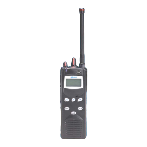
M/A-Com P7100 Series Operator's Manual
Hide thumbs
Also See for P7100 Series:
- Operator's manual (109 pages) ,
- Installation manual (101 pages) ,
- Installation and safety manual (72 pages)
Table of Contents
Advertisement
Advertisement
Table of Contents

Related Manuals for M/A-Com P7100 Series


Summary of Contents for M/A-Com P7100 Series
- Page 1 Operator’s Manual MM101332V1 Rev. Fp2, June-04 P7100 Series Portable Radios...
- Page 2 M/A-COM, Inc., at any time and without notice. Such changes will be incorporated into new editions of this manual. No part of...
-
Page 4: Table Of Contents
TABLE OF CONTENTS Page SAFETY TRAINING INFORMATION ..........5 SAFETY CONVENTIONS..............7 OPERATING TIPS ................8 BATTERY DISPOSAL..............10 INTRODUCTION ................11 OPTIONS AND ACCESSORIES ............12 USER INTERFACE .................14 CONVENTIONAL OPERATION ...........27 BASIC OPERATION...............28 TRUNKED OPERATION..............40 PROJECT 25 (P25) CONVENTIONAL OPERATION....56 OPERATION FOLLOWING WATER CONTACT ......59 CHANGING THE BATTERY PACK ..........60 BATTERY WARRANTY..............61 WARRANTY ...................62... -
Page 5: Safety Training Information
The P7100 portable radio has been tested and complies with the FCC RF exposure limits for “Occupational Use Only.” In addition, this M/A-COM radio complies with the following Standards and Guidelines with regard to RF energy and electromagnetic energy levels and evaluation of such levels for exposure to humans: •... - Page 6 FCC RF exposure limits of this radio. ELECTROMAGNETIC INTERFERENCE/COMPATIBILITY During transmissions, this M/A-COM radio generates RF energy that can possibly cause interference with other devices or systems. To avoid such interference, turn off the radio in areas where signs are posted to do so. DO NOT operate the transmitter in areas that are sensitive to electromagnetic radiation such as hospitals, aircraft, and blasting sites.
-
Page 7: Safety Conventions
SAFETY CONVENTIONS The WARNING symbol calls attention to a procedure, practice, or the like, which, if not correctly performed or adhered to, could result in personal injury. Do not proceed beyond a WARNING symbol until the conditions identified WARNING are fully understood or met. The CAUTION symbol calls attention to an operating procedure, practice, or the like, which, if not performed correctly or adhered to, could result in damage to the... -
Page 8: Operating Tips
OPERATING TIPS Antenna location and condition are important when operating a portable radio. Operating the radio in low lying areas or terrain, under power lines or bridges, inside of a vehicle or in a metal framed building can severely reduce the range of the unit. - Page 9 Use only the supplied or approved antenna. Unauthorized antennas, modifications or attachments could cause damage to the radio unit and may violate FCC regulations. (Refer to Table WARNING 2: Options and Accessories.) Electronic Devices RF energy from portable radios may affect some electronic equipment.
-
Page 10: Battery Disposal
BATTERY DISPOSAL The P7100 series portable radios use rechargeable, recyclable Nickel Cadmium (NiCd) or Nickel Metal Hydride (NiMH) batteries. NICKEL CADMIUM BATTERY At the end of its useful life, under various state and local laws, it may be illegal to dispose of Nickel Cadmium batteries into the municipal waste stream. -
Page 11: Introduction
INTRODUCTION This manual describes how to use the P7100 series portable radio. The P7100 series radios synthesized, microprocessor-based, high performance portable FM radios providing reliable two-way communications ® in both the Enhanced Digital Access Communications Systems (EDACS trunking environment and conventional communications systems. In EDACS (trunked) mode, the user selects a communications system and group. -
Page 12: Options And Accessories
Items for use with a specific band split or part number are noted. Refer to the maintenance manual or to M/A-COM’s Products and Services Catalog for a complete list of options and accessories, including those items that do not adversely affect the RF energy exposure. - Page 13 DESCRIPTION PART NUMBER ISCELLANEOUS CCESSORIES Speaker Mic <IS> KRY 101 1617/183 Speaker Mic Antenna Version Plus <IS> KRY 101 1617/184 Speaker Mic, Charger Compatible <IS> KRY 101 1617/185 Speaker Mic, Ant. Version, Charger Comp. <IS> KRY 101 1617/186 Speaker Mic, Immersible <IS> KRY 101 1617/283 Speaker Mic, Ant.
-
Page 14: User Interface
USER INTERFACE Figure 1: Top View Figure 2: Side View... - Page 15 Figure 3: System Model...
- Page 16 Figure 4: Scan Model CONTROLS The radio features two rotary control knobs and an emergency button mounted on the top of the radio. Push-To-Talk, option and monitor buttons are mounted on the side. The front mounted keypad has six buttons on the P7150 Scan model and 15 buttons on the P7170 System Radio.
- Page 17 into the radio to prevent missed calls due to a low volume setting. While adjusting the volume the display will momentarily indicate the volume level (i.e. VOL=31). The volume range is from a minimum programmed level of zero (displayed as OFF in the display) up to 31, which is the loudest level.
- Page 18 Keypad The keys on the Keypad have special functions and are labeled using a symbol or abbreviated word describing its primary function. Numeric entry is a secondary function of the keys. Each key is described in the following subsections. Figure 5: Scan Radio Front Panel FUNCTION Primary Function: Allows the user to select system, groups,...
- Page 19 FUNCTION Activates one of a number of programmable software options. (Scan only) Figure 6: System Radio Front Panel...
- Page 20 FUNCTION Same as Scan Model Same as Scan Model Selects a specific system. If the rotary knob is used to select the system and more than 16 systems are programmed in the radio, the key is used to select additional banks (groupings) of systems. These keys are used to place telephone interconnect and 1-9, *, 0, # individual (unit-to-unit) calls.
- Page 21 DISPLAY The radio Display is made up of 3 lines (see Figure 7). Lines 1 and 2 contain eight alphanumeric character blocks and are used primarily to display system and group names. Line 1 also displays radio status messages. The 3rd line is used primarily to display radio status icons.
-
Page 22: Radio Status Icons
Radio Status Icons Status Icons indicate the various operating characteristics of the radio. The icons show operating modes and conditions and appear on the third line of the display (see Table 3). Table 3: Display Icons Icon Descriptions Steady – “Busy” transmitting or receiving Flashing –... - Page 23 Figure 8: Battery Charge Icons (Full Cycle) The battery icons (see Figure 8) indicate approximate level only, based on battery voltage. Figure 9: Tri-Color LED Tri-Color LED The Tri-Color LED changes color to indicate radio status and is visible from both the front and top of the radio (see Figure 9).
-
Page 24: Status Messages
Status Messages During radio operation, various radio Status Messages can be displayed. The messages are described below. MESSAGE NAME DESCRIPTION QUEUED Call Queued Trunked mode only. Indicates the system has placed the call in a request queue. SYS BUSY System Busy Trunked mode only. -
Page 25: Error Messages
Error Messages If either of the Error Messages shown below is displayed, the radio is programmed incorrectly or needs servicing. DIG V ERR=XXXX (PowerUp only) xxxx DSP ERR DIG V ERR Where: is the error code and is the message. ALERT TONES The P7100 radio provides audible Alert Tones or “beeps”... - Page 26 UNIVERSAL DEVICE CONNECTOR (UDC) The Universal Device Connector (UDC) provides connections for external accessories such as a headset or a speaker-microphone. The UDC is located on the right side of the radio (opposite the PTT Button). When the radio is locked in a vehicular charger the UDC provides the audio and control connections between the radio and the vehicular charger.
-
Page 27: Conventional Operation
CONVENTIONAL OPERATION In addition to the features covered in the following BASIC OPERATION section, the following functions are for the conventional mode. The radio functions in the conventional mode when using conventional communications channels (non-trunked). RECEIVING A CALL 1. Select desired conventional system and channel or turn scan ON and make sure desired channel is in scan list. -
Page 28: Basic Operation
BASIC OPERATION TURNING ON THE RADIO 1. Power ON the radio by rotating the POWER ON-OFF/VOLUME knob clockwise. A short alert signal (if enabled through programming) indicates the radio is ready to use. Refer to Figure 1 for location of the POWER ON-OFF/VOLUME KNOB. -
Page 29: Group Selection
GROUP SELECTION Method 1 (System Model) 1. Press to access group list. 2. Press to scroll through the list of groups or the numeric key mapped to the desired group list. 3. Press to select desired group. The radio will move to the selected group. -
Page 30: Contrast Adjust
Press twice to add as a Priority 2 group. Press three times to add as a Priority 1 group. 5. Press to re-start scanning. NUISANCE DELETE (SYSTEM MODEL) A channel can temporarily be deleted from the scan list if it is not the currently selected channel. - Page 31 3. *TXEMER* and will remain until the emergency is cleared. 4. Press the PTT and will reappear. 5. Release PTT when the transmission is complete. LOCKING/UNLOCKING KEYPAD 1. Press button. 2. Within 1 second, press the Option button on the side of the radio. HIGH/LOW POWER ADJUSTMENT Transmit power adjustment is possible if enabled through programming.
- Page 32 2. Upon entering the menu selection mode, Menu options will appear on the display (see Figure 10). Figure 10: Menu Display 3. The radio will continue to receive and transmit normally while in the menu function. 4. To scroll through the menu options use the keys.
- Page 33 4. The menu item's parameter setting shown in the display can now be changed by using 5. Once the desired setting is reached press to store the value and return the menu option selection level. For menu items that display radio information pressing will scroll through a list of informational displays.
- Page 34 FEATURE DISPLAY PARAMETER COMMENT SETTING Toggle Scan SCAN ON/OFF Toggles Scan On/Off operation ON/OFF. Toggle PRIVATE ON/OFF Toggles Private Mode Private ON/OFF. Mode Display DISP KEY Displays current Current encryption key. Encryption Informational display only. No selectable settings. Display HOME Selects Home Current Group/Channel...
-
Page 35: Digital Voice Operation
DSP_ _RAM DSP Software Version FLSH - VER FLASH Software r - released, 01A - revision state M/A-COM Copyright (C) – 2003-2004 Figure 12: Information Display DIGITAL VOICE OPERATION Digital voice programmed systems have three (3) different voice modes: clear (analog), digital, and private (encrypted). - Page 36 Clear Mode The Clear Mode is a voice mode in which the radio transmits and receives only clear (analog) voice signals. These analog signals are non-digitized and non-encrypted. Clear mode transmissions can be monitored easily by unauthorized persons. Groups or channels programmed for clear operation cannot transmit or receive digital or private messages.
- Page 37 automatically selected on a per-group/channel basis according to the radio programming. Groups and channels within the digital system can be programmed for keys 1-7 (private). Up to 8 banks of 7 keys can be stored for private systems. The bank is specified per system. When operating on a group or channel programmed for Private Mode, all transmissions are private transmissions and the radio receives clear and private signals.
- Page 38 Key Zero All cryptographic keys can be zeroed (erased from radio memory) by pressing the MONITOR/CLEAR button and while still pressing this button, press and hold the OPTION button. Press both buttons for 2 seconds. A series of beeps will begin at the start of the 2 second period and then switch to a solid tone KEY ZERO after the keys have been zeroed.
- Page 39 Scanned Group Calls Receiving a Scanned Group Call is the same as receiving a selected group call. During the scan hang time, if the radio was programmed for autoselect, it will transmit back in the same mode it received the call. For example, if a clear group is entered in the scan list, it will only receive clear calls.
-
Page 40: Trunked Operation
TRUNKED OPERATION SCANNING TRUNKED GROUPS Groups that have been previously added to the scan list on a per system basis may be scanned. Each system's group scan list is retained in memory when the radio is powered OFF or when the battery pack is removed. The following procedures outline scan operations for trunked groups. - Page 41 4. Press the key a second time to set the group to Priority 2. A displayed on line three. Press a third time to set the group to Priority 1. A is displayed on line three. The priority level section sequence only advances the group to the next high priority level and stops at priority level 1.
- Page 42 Press a third time to set the group to Priority 1. A is displayed on line three. The priority level selection sequence only advances the group to next higher priority level and stops at priority level 1. To select a lower priority level, the group must be deleted from the scan list and then added back to the scan list.
-
Page 43: Scanning Trunked Systems
While the status is displayed, press to delete the group from the scan list. turns OFF. Any group that is not in a trunked system group scan list will show a "blank" for the time out period when it is the selected channel. Nuisance Delete A group can also be deleted from the scan list, if it is not the currently selected group, by pressing the... -
Page 44: Emergency Operation
When ProScan is Enabled The radio monitors the priority system and will switch to the priority system if the criteria defined by the controls in the ProScan Options dialog box are met. If ProScan is enabled, the rate at which the radio will scan for the priority system is defined by the System Sample Time control, located in the ProScan Options dialog box. -
Page 45: Individual Calls
Receiving an Emergency Call When Receiving An Emergency Call on the selected group and system, an *RXEMER* alert beep is heard and is displayed. The message flashes in the display on line two until the emergency condition is cleared. Declaring an Emergency Call To send an emergency call to a selected system and group (or on an optionally pre-programmed group), proceed as follows: 1. - Page 46 If a response is made by pressing the PTT to the call prior to the programmed call-back time-out, the call will automatically be directed to the originating unit. If a response is not made before the call-back time-out, the radio will *WHC* return to normal receive display, and will appear on the first line of...
- Page 47 Sending an Individual Call (Trunked Mode Only) Pre-Stored Individual Calls The following procedures describe how to initiate and complete a Pre-Stored Individual Call. System Model 1. To select a pre-stored individual phone number, enter the individual call mode using the key.
-
Page 48: Telephone Interconnect Calls
Call Storage Lists There are two lists available for call storage in the P7100 series radios, the calls received list (1 - 10) and the personality list (1 - 99 as defined by the user). When the individual call mode is entered by pressing , the calls received list is available. - Page 49 Sending a Telephone Interconnect Call (Trunked Mode Only) Pre-Stored Number Use the following procedures to initiate and complete a Telephone Interconnect call: 1. System Model: To select a previously stored phone number, press Use the keys to scroll through the list of stored numbers. Scan Model: To select a previously stored phone number, press .
- Page 50 2. If the phone number is not stored in the pre-stored list of phone numbers, but the phone number is known, it can be entered directly from the keypad. Start by pressing the . Then enter the required number from the keypad.
-
Page 51: Programmable Entries
Press to enter the overdial select/entry mode and follow the selection mode rules to call up a stored number from the phone list. is displayed. Press PTT to send the overdial sequence once. If the number needs to be transmitted again it must be selected or entered again (this prevents unwanted numbers from being sent the next time the PTT button is pressed during the call). - Page 52 4. Press and hold until the display changes indicating that the number has been stored. Repeat steps 1-4 above if the number stored in an entry location needs to be changed. STATUS/MESSAGE OPERATION Status operation permits the transmission of a pre-programmed status condition to the EDACS site.
-
Page 53: Portable Data
until the system manager sends an activation message. Each radio that receives and acknowledges the regrouping instructions is successfully regrouped. Pressing and holding the CLEAR/MONITOR button for 2.5 seconds toggles the user into and out of the dynamic regroup groupset. A double beep will REGRP_0x sound for entry or exit. - Page 54 Displays The following will be displayed during the various states of data mode of operation: TX DATA Appears on top line of display when the radio is transmitting a data call. RX DATA Appears on top line of display when the radio is receiving a data call.
- Page 55 • A group or system is changed. Scan Lockout Mode Following the transmission or reception of a data call, if scan is enabled, scanning will stop temporarily (two independent pre-programmed times; after a receive data call and after a transmit data call). During this time the scan indicator will flash to indicate that scan is enabled but temporarily suspended.
-
Page 56: Project 25 (P25) Conventional Operation
PROJECT 25 (P25) CONVENTIONAL OPERATION GROUP CALLS IN P25 MODE Transmitting a Group Call 1. Select the desired P25 system. (P25 icon will appear in display.) 2. Select the Talk Group/Conventional Channel. (Selected simultaneously using either the system/group/channel knob or the group key.) 3. -
Page 57: Emergency Group Calls In P25 Mode
Receiving an Individual Call The radio will unmute according to the squelch mode defined in the radio personality (monitor, normal, selective). 1. Select the desired P25 system and Talk Group/Channel or turn scan on and make sure the desired channel is in the scan list. 2. - Page 58 Receiving an Emergency Group Call 1. Select the desired P25 System and Talk Group/Channel. 2. When the radio detects an incoming Emergency Group Call, the radio will sound an alert tone and “RXEMER” will appear in the display. 3. Voice or emergency transmissions will be heard at the receiving radio. 4.
-
Page 59: Operation Following Water Contact
OPERATION FOLLOWING WATER CONTACT If the P7100 model radio has been immersed in water or if the microphone air path or speaker grill become clogged with water, follow instructions under “Radio Microphone” and “Radio Speaker” sections to assure the highest quality transmitted and received messages. -
Page 60: Changing The Battery Pack
CHANGING THE BATTERY PACK REMOVING THE BATTERY PACK Make sure the power to the radio is turned OFF. 1. Press the latch at the bottom of the battery pack. 2. Lift the battery pack from the bottom. 3. Remove the battery pack from the radio. Figure 19: Removing the Battery Pack ATTACHING THE BATTERY PACK Make sure the power to the radio is turned OFF. -
Page 61: Battery Warranty
BATTERY WARRANTY M/A-COM, Inc. (hereinafter "Seller") warrants to the original purchaser for use (hereinafter "Buyer") that nickel-cadmium and nickel-metal hydride batteries supplied by Seller shall be free from defects in material and workmanship, and shall conform to its published specifications for a period of twelve (12) months from the date of purchase. -
Page 62: Warranty
Equipment covered under Paragraph B.3 and B.4. To be eligible for no-charge labor, service must be performed at a M/A-COM factory, by an Authorized Service Center (ASC) or other Servicer approved for these purposes either at its place of business during normal business hours, for mobile or personal equipment, or at the Buyer’s location, for... - Page 63 M/A-COM Technical Publications would particularly appreciate feedback on any errors found in this document and suggestions on how the document could be improved. Submit your comments and suggestions to: Wireless Systems Business Unit M/A-COM, Inc. fax your comments to: (434) 455-6851...
- Page 64 M/A-COM Wireless Systems 221 Jefferson Ridge Parkway Lynchburg, Virginia 24501 (Outside USA, 434-385-2400) Toll Free 800-528-7711 www.macom-wireless.com Printed in U.S.A.
Need help?
Do you have a question about the P7100 Series and is the answer not in the manual?
Questions and answers