Table of Contents
Advertisement
Instructions - Parts
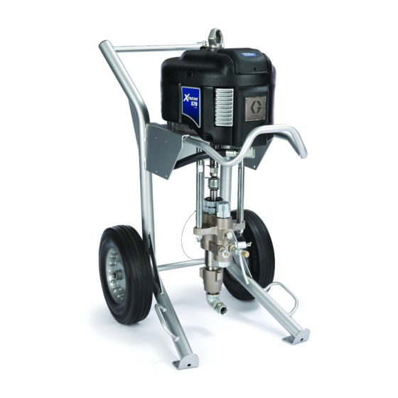
Xtreme Packages
High performance, high pressure spray packages for protective coatings. For professional
use only.
Important Safety Instructions
Read all warnings and instructions in this manual.
Save these instructions.
See page 4 for model information and maximum working pressures.
311164M
EN
r_x25dh1_x45dl1_311164_1f
II 2 G
Advertisement
Chapters
Table of Contents

Related Manuals for Graco xtreme


Summary of Contents for Graco xtreme
- Page 1 Instructions - Parts Xtreme Packages 311164M High performance, high pressure spray packages for protective coatings. For professional use only. Important Safety Instructions Read all warnings and instructions in this manual. Save these instructions. See page 4 for model information and maximum working pressures.
-
Page 2: Table Of Contents
Preventive Maintenance Schedule ..18 Graco Information ......60 Daily Maintenance . -
Page 3: Related Manuals
™ 311486 DataTrak Conversion Kit Air Controls for Heavy and Light Duty Carts Instructions-Parts 3A0293 The Xtreme Packages manual is available in the following languages. See the following chart for specific languages and corresponding part numbers. Manual Language English 311164... -
Page 4: Models
For example, Sprayer Part Number X 60 D H 1 represents the Xtreme brand (X), pressure ratio (60 :1), de-icing motor (D), heavy duty cart (H), and complete package (gun and ™... -
Page 5: Specialty Sprayer Packages
For example, cart package number X N3 D H 2 represents the ™ Xtreme brand (X), motor (NXT3400), de-icing motor (D), heavy duty cart (H), and bare package with DataTrak (2). -
Page 6: Pump Packages
Models Pump Packages Check your pump package’s identification plate (ID) for the 6-digit part number of your pump package. For example, Pump Part Number P 30 M C 1 rep- resents the pump (P), pressure ratio (30 :1), low noise exhaust motor with ™... -
Page 7: Warnings
Warnings Warnings The following warnings are for the setup, use, grounding, maintenance, and repair of this equipment. The exclama- tion point symbol alerts you to a general warning and the hazard symbols refer to procedure-specific risks. Refer back to these Warnings. Additional, product-specific warnings may be found throughout the body of this manual where applicable. - Page 8 Read fluid and solvent manufacturer’s warnings. For complete information about your material, request MSDS forms from distributor or retailer. • Check equipment daily. Repair or replace worn or damaged parts immediately with genuine Graco replacement parts only. •...
-
Page 9: Component Identification - Cart Mount
Component Identification - Cart Mount Component Identification - Cart Mount Air Inlet, 3/4 npt(f) Fluid Filter Bleed Type Master Air Valve (required) Grounding Wire (required) Air Pressure Relief Valve Lower Air Filter (hidden) Suction Hose and Tube Air Pressure Gauge Fluid Outlet Air Regulator Adjustment Knob Optional Fluid Outlet, for second gun... -
Page 10: Component Identification - Wall Mount
Component Identification - Wall Mount Component Identification - Wall Mount Air Inlet, 3/4 npt(f) Grounding Wire (required) Bleed Type Master Air Valve (required) Lower Air Pressure Relief Valve Suction Hose and Tube Air Filter (hidden) Fluid Outlet Air Pressure Gauge Optional Fluid Outlet, for second gun Air Regulator Adjustment Knob Packing Nut... -
Page 11: System Components
Component Identification - Wall Mount System Components * Bleed Type Master Air Valve (B) Air Regulator Adjustment (F) Adjusts air pressure to the motor and fluid outlet pres- sure of pump. Locate it close to the pump. Read air pressure on gauge (E). Trapped air can cause the pump to cycle unexpectedly, * Fluid Drain/Purge Valve (J) which could result in serious injury from splashing or... -
Page 12: Grounding
Grounding Grounding Setup To avoid tip over, ensure cart is on a flat and level sur- face. Failure to do so could result in injury or equip- The equipment must be grounded. Grounding reduces ment damage. the risk of static and electric shock by providing an escape wire for the electrical current due to static build Table 2: Tools Required up or in the event of a short circuit. -
Page 13: Pressure Relief Procedure
Pressure Relief Procedure Pressure Relief Procedure 4. Hold gun firmly against a grounded metal pail. Trig- ger the gun. 1. Engage gun trigger lock. TI8252a 5. Engage gun trigger lock. TI5049a 2. Close bleed type master air valve (B). TI5049a 6. -
Page 14: Prime/Flush
Prime/Flush Prime/Flush 1. Follow Pressure Relief Procedure, page 13. 7. Prime or flush hose and gun: 2. Remove tip and tip guard from gun. a. Disengage gun trigger lock. 3. Flushing only: If desired, remove built-in fluid filter (present on some models). Reinstall filter cap after removing fluid filter. - Page 15 Prime/Flush 11. When clean solvent flows from drain tube close NOTE: The remaining steps are for flushing drain/purge valve (J) by rotating clockwise. Pump only. will stall. CAUTION Do not prime pump through drain/purge valve using two component materials. Mixed two-component materials will harden in valve and result in clogging.
-
Page 16: Spray
Spray Spray CAUTION Do not allow pump to run dry. It will quickly accelerate to a high speed causing damage. 1. Prime. See Prime/Flush, page 14. 7. Spray a test pattern. Read fluid manufacturer’s rec- ommendations. Adjust as necessary. If using an AA 2. -
Page 17: Shutdown
Shutdown Shutdown 5. Open bleed type master air valve (B). Turn regulator adjustment knob (G) counterclockwise to lowest possible fluid pressure. CAUTION Never leave water or water-base fluid in pump over- night. If you are pumping water-base fluid, flush with water first, then with a rust inhibitor, such as mineral spirits solvent (also called white spirit). -
Page 18: Maintenance
Maintenance Maintenance Preventive Maintenance Corrosion Protection Schedule Always flush the pump before the fluid dries on the dis- placement rod. Never leave water or water-based fluid in The operating conditions of your particular system the pump overnight. First, flush with water or a compati- determine how often maintenance is required. -
Page 19: Datatrak Controls And Indicators
DataTrak Controls and Indicators DataTrak Controls and Indicators NOTE: DataTrak is included with certain mod- els. See Models, page 4, for a list of models fea- turing DataTrak. Key for F Runaway Limit, in cycles per minute (user settable; RK Reset Key (Resets faults. Press and hold for 3 seconds to 00=OFF) clear the batch totalizer.) Lower Displacement (user settable) -
Page 20: Datatrak Operation
DataTrak Operation DataTrak Operation Run Mode NOTE: To prevent damage to the DataTrak soft key buttons, do not press the buttons with sharp objects such as pens, plastic cards, or Runaway fingernails. 1. See F . 5. If pump runaway occurs, the runaway solenoid will actuate, stopping the pump. - Page 21 DataTrak Operation Prime/Flush Display 1. See F . 5. To enter Prime/Flush mode, press any See F . 5. The display (Y) will turn off after 1 minute of inactivity in Run mode or 3 minutes in Setup mode. key to wake up the display, then press .
- Page 22 DataTrak Operation Table 3: Diagnostic Codes Symbol Code Code Name Diagnosis Cause Runaway Pump running faster than set runaway • Increased air pressure. limit. • Increased fluid output. • Exhausted fluid supply. Diving Up Leak during upstroke. Worn piston valve or packings. Diving Down Leak during downstroke.
-
Page 23: Troubleshooting
Clear or service intake valve. Runs sluggishly. Possible icing. Stop pump. Open De-Ice control; see page Service lower. See Xtreme Lower Removal, Cycles or fails to hold Worn check valves or seals. pressure at stall. page 24, and Xtreme Lowers manual (311762). -
Page 24: Xtreme Lower Removal
Xtreme Lower Removal Xtreme Lower Removal Required Tools 4. Disconnect fluid hose (103). Disconnect suction hose (4). Hold fluid outlet fitting (6) with a wrench to • Set of adjustable wrenches keep it from loosening while you disconnect suction •... - Page 25 Xtreme Lower Removal 6. Remove clip (309), and slide coupling cover (307) 8. Refer to the Xtreme Lower manual (311762) to ser- up to remove coupling (305). vice lower. To service motor, refer to separate motor manual. 9. Reconnect lower by following disconnect steps in reverse order.
-
Page 26: Wall Mount Assembly
Wall Mount Assembly Wall Mount Assembly Hopper Assembly NOTE: Before mounting any pump assembly to 1. Hang hopper bracket (109b) on hose rack of sprayer the wall always follow the Pressure Relief Pro- cart. cedure, page 13. 2. Attach hanger bracket (109c) to hopper bracket 1. - Page 27 Hopper Assembly 311164M...
-
Page 28: Airless Xtreme Sprayer Parts
Airless Xtreme Sprayer Parts Airless Xtreme Sprayer Parts Complete Sprayer Shown (includes hose and gun) r_x25dh1_x45dl1_311164_27f For pumps P45DC1, P60DC1, and P70DC1 r_x25dh1_x45dh7 . 6: X45DL1 Model Shown 311164M... -
Page 29: Wall Mount Xtreme Package Parts
Wall Mount Xtreme Package Parts Wall Mount Xtreme Package Parts 211a 211b TI8423a For pump 287978 TI8810a . 7: Wall Mount Package 311164M... -
Page 30: Parts - Airless Xtreme Sprayer Packages
Parts - Airless Xtreme Sprayer Packages Parts - Airless Xtreme Sprayer Packages The following table lists the major components and part numbers for each airless sprayer package. Refer to Com- mon Parts, starting on page 35, for parts included with each airless sprayer package. - Page 31 Parts - Airless Xtreme Sprayer Packages Reference Number and Description Reference Number and Description Sprayer Sprayer Package Package Pump Lower Motor Pump Lower Motor (see pg 43) (see 311762) (see 311238) (see pg 43) (see 311762) (see 311238) X40DL3 P40DC2...
- Page 32 Parts - Airless Xtreme Sprayer Packages Reference Number and Description Reference Number and Description Sprayer Sprayer Package Package Pump Lower Motor Pump Lower Motor (see pg 43) (see 311762) (see 311238) (see pg 43) (see 311762) (see 311238) X50DW4 P50DC4...
- Page 33 Parts - Airless Xtreme Sprayer Packages Reference Number and Description Reference Number and Description Sprayer Sprayer Package Package Pump Lower Motor Pump Lower Motor (see pg 43) (see 311762) (see 311238) (see pg 43) (see 311762) (see 311238) X60LH6 P60LC2...
- Page 34 Parts - Airless Xtreme Sprayer Packages Hopper Options Reference Number and Description Sprayer If your sprayer package includes a hopper, use the fol- Package lowing table to determine the specific hopper option. For Pump Lower Motor example, X60DH5 indicates the airless sprayer package...
-
Page 35: Common Parts
Parts - Airless Xtreme Sprayer Packages Common Parts Airless Sprayer Packages The following parts are included with only complete air- less sprayer packages: The following parts are included with each airless sprayer package: Ref. Part Description Qty. Ref. Part Description Qty. -
Page 36: Wall Mount Packages
Parts - Airless Xtreme Sprayer Packages Airless Sprayers with Hopper Packages Wall Mount Packages Ref. Part Description Qty. Hopper kit is shown on page 26. 197682 TUBE, suction Ref. Part Description Qty. 247302 HOSE, suction,1 in., NPT x quick connect; 10 ft. -
Page 37: Air-Assisted Xtreme Sprayer Parts
Air-Assisted Xtreme Sprayer Parts Air-Assisted Xtreme Sprayer Parts 438* (To air inlet) 416* To air control 436* 437* 410* 440* 439* 417* 441* 431* 428* 430* 415* 427* 435* 410* 428* 415* 427* 435* Side View - Air Regulator Mounting Kit 288527 . -
Page 38: Zinc Xtreme Sprayer Parts
Zinc Xtreme Sprayer Parts Zinc Xtreme Sprayer Parts 533† TI8754a r_x25dh1_x45dh1_311164_34 (Fluid Return Line) . 9: Model 287973 Shown 311164M... -
Page 39: Parts - Air-Assisted And Zinc Sprayer Packages
Parts - Air-Assisted and Zinc Sprayer Packages Parts - Air-Assisted and Zinc Sprayer Packages Air-Assisted Sprayer Packages Zinc Sprayer Packages Models 287975 and 287976 Models 287971, 287972, 287973, 287974 Ref. Part Description Qty. Ref. Part Description Qty. P30DC2 PUMP, assy. 287975 P25DC1 PUMP, assy. -
Page 40: Dura-Flo Sprayer Parts
Dura-Flo Sprayer Parts Dura-Flo Sprayer Parts 617, 618 629† 630† 642† 632† 631† TI9162a 636† 634† 637† 635† 633† 604, 605 638† 639† 631† 640† r_287979_311164_36f . 10: Model 287980 311164M... -
Page 41: Parts - Dura-Flo Sprayer Packages
Parts - Dura-Flo Sprayer Packages Parts - Dura-Flo Sprayer Packages Model 287979, 287980, and 287981 Ref. Part Description Qty. 629† 103475 FITTING, tee, pipe NOTE: Model 287980 is the only model that 630† 102646 VALVE, ball includes a gun and hose. 631†... -
Page 42: Cart Parts
Cart Parts Cart Parts Heavy Duty Cart, Model 287884 Light Weight Cart, Model 287919 r_x25dh1_x45dh1_311164_38f TI8409a Ref. Part Description Qty. Ref. Part Description Qty. 116406 WHEEL, semi-pneumatic 113361 CAP, tube, round 113436 RING, retaining 113362 WHEEL, semi-pneumatic WASHER 113436 RING, retaining 311164M... -
Page 43: Pump Package Parts
Pump Package Parts Pump Package Parts Pump Package Parts List Page Pump Packages with L085C# Lowers (80:1 ratio) pg 44 Pump Packages with L115C# Lowers (35:1, 55:1 ratio) pg 45 Pump Packages with L145C# and L14AC1 Lowers (31:1, 46:1, 90:1 ratio) pg 46 Pump Packages with L180C# and L18AC1 Lowers (24:1, 40:1, 70:1 ratio) pg 47... -
Page 44: Pump Packages With L085C# Lowers (80:1 Ratio)
Pump Packages with L085C# Lowers (80:1 ratio) Pump Packages with L085C# Lowers (80:1 ratio) Reference Number and Description Pump Control Package Clip, De-ice (NXT021) Built-in Coupling, Rod, Cover, Nut, hairpin w/ Adapter, Control Lower Motor (see Filter assy. coupler lock lanyard Knob (see 311762) -
Page 45: Pump Packages With L115C# Lowers
Pump Packages with L115C# Lowers (35:1, 55:1 ratio) Pump Packages with L115C# Lowers (35:1, 55:1 ratio) Reference Number and Description Pump Control Package Clip, De-ice (NXT021) Built-in Coupling, Rod, Cover, Nut, hairpin w/ Adapter, Control Lower Motor (see Filter assy. coupler lock lanyard... -
Page 46: Pump Packages With L145C# And L14Ac1 Lowers (31:1, 46:1, 90:1 Ratio)
Pump Packages with L145C# and L14AC1 Lowers (31:1, 46:1, 90:1 ratio) Pump Packages with L145C# and L14AC1 Lowers (31:1, 46:1, 90:1 ratio) Reference Number and Description *304 Pump Control Package Clip, De-ice (NXT021) Built-in Coupling, Rod, Cover, Nut, hairpin w/ Adapter, Control Lower... -
Page 47: Pump Packages With L180C# And L18Ac1 Lowers (24:1, 40:1, 70:1 Ratio)
Pump Packages with L180C# and L18AC1 Lowers (24:1, 40:1, 70:1 ratio) Pump Packages with L180C# and L18AC1 Lowers (24:1, 40:1, 70:1 ratio) Reference Number and Description Pump Control Package Clip, De-ice (NXT021) Built-in Lower Motor Coupling, Rod, Cover, Nut, hairpin w/ Adapter, Control (see... -
Page 48: Pump Packages With L220C# Lowers (21:1, 30:1, 60:1 Ratio)
Pump Packages with L220C# Lowers (21:1, 30:1, 60:1 ratio) Pump Packages with L220C# Lowers (21:1, 30:1, 60:1 ratio) Reference Number and Description Pump Control Package Clip, De-ice (NXT021) Built-in Lower Motor Coupling, Rod, Cover, Nut, hairpin w/ Adapter, Control (see Filter assy. -
Page 49: Pump Packages With L250C# Lowers (50:1 Ratio)
Pump Packages with L250C# Lowers (50:1 ratio) Pump Packages with L250C# Lowers (50:1 ratio) Reference Number and Description Pump Control Package Clip, De-ice (NXT021) Built-in Lower Motor Coupling, Rod, Cover, Nut, hairpin w/ Adapter, Control (see Filter assy. coupler lock lanyard Knob (see 311762) -
Page 50: Pump Packages With L290C# Lowers
Pump Packages with L290C# Lowers (16:1, 25:1, 45:1 ratio) ratio) Pump Packages with L290C# Lowers (16:1, 25:1, 45:1 Reference Number and Description Pump Control Package Clip, De-ice (NXT021) Built-in Lower Motor Coupling, Rod, Cover, Nut, hairpin w/ Adapter, Control (see Filter assy. -
Page 51: Dimensions
Model X60DH3 Shown Top View - Heavy Duty Cart Shown r_x25dh1_x45dh1_311164_47f2 r_x25dh1_x45dh1_311164_47f KEY: HD = Heavy Duty Cart LW = Light Weight Cart All Xtreme Sprayer (Cart Mounted) Packages Mount 43.69 in. 46.0 in. 32.0 in. 35.0 in. 25.72 in. - Page 52 Dimensions Wall Mount Packages and Pump Packages Front View Side View TI8424a TI8425a Wall Mount Dimensions NOTE: Dimensions based on largest air motor and lower combination. 14.0 in. 17.75 in. 29.0 in. 19.25 in. 43.0 in. 18.9 in. 16.2 in. (355.6 mm) (450.6 mm) (736.6 mm)
-
Page 53: Weights
Dimensions Weights NOTE: Weights are approximate and do not include hoses or guns. Sprayer (Cart Mounted) Wall Mount Pump Assembly Packages Packages Packages No Filter, No Air Heavy Duty Cart Light Weight Cart Controls❄ Ratio lbs (kg) lbs (kg) Ratio lbs (kg) Ratio lbs (kg) -
Page 54: Mounting Hole Diagram
Mounting Hole Diagram Mounting Hole Diagram Wall Mount Bracket 17.8 in. (450.9 mm) 14.5 in. (368.3 mm) 2.0 in. (50.8 mm) 5.4 in. (136.5 mm) 7.4 in. (187.3 mm) 5.3 in. (133.4 mm) 1.0 in. (25.4 mm) 9.0 in. (228.6 mm) 1.6 in. -
Page 55: Accessories
Accessories Accessories Adapter Plate 247312 Adapter plate is required to mount pump assemblies with an NXT2200 air motor to cart or wall mount bracket. NXT021 Air Control Module Includes Safety Relief Valve 113498 (pressure relief at 110 psi (7.7 MPa, 77 bar)). If you have a 90:1 pump package, also order Safety Relief Valve 116643 (pres- sure relief at 90 psi (6.3 MPa, 63 bar)). -
Page 56: Technical Data
Technical Data Technical Data Maximum air inlet pressure Models with 16:1 - 80:1 pressure ratios: 100 psi (0.7 MPa, 7 bar). Models with a 90:1 pressure ratio: 80 psi (0.55 MPa, 5.5 bar). NXT Model 6500: 10.375 in. (264 mm) Air motor piston diameter NXT Model 3400: 7.5 in. -
Page 57: Pump Package Performance Charts
Key: Air Pressure 100 psi (0.7 MPa, 7 bar) 70 psi (0.5 MPa, 7.8 bar) 40 psi (0.3 MPa, 2.8 bar) Dashed lines indicate low noise motors. 16:1 Xtreme Pumps 21:1 Xtreme Pumps 1600 2500 (2.2) (11.2, 112) (2.2) - Page 58 Pump Package Performance Charts Pump Package Performance Charts (cont.) 31:1 Xtreme Pumps 30:1 Xtreme Pumps 3000 3500 (3.4) (21.0, 210) (4.5) (24.5, 245) 2500 2000 (3.4) (17.5, 175) (2.2) (14.0, 140) 1500 (2.2) 1000 (10.5, 105) (1.1) (7.0, 70) (1.1) (3.5, 35)
- Page 59 Pump Package Performance Charts Pump Package Performance Charts (cont.) 50:1 Xtreme Pumps 55:1 Xtreme Pumps 6000 7000 (7.0) (4.5) (42.0, 420) (49.0, 490) (5.6) 5000 (3.4) 4000 (35.0, 350) (28.0, 280) (4.2) 3000 (2.2) 2000 (21.0, 210) (2.8) (14.0, 140) (1.1)
-
Page 60: Graco Standard Warranty
With the exception of any special, extended, or limited warranty published by Graco, Graco will, for a period of twelve months from the date of sale, repair or replace any part of the equipment determined by Graco to be defective.
Need help?
Do you have a question about the xtreme and is the answer not in the manual?
Questions and answers