
Subscribe to Our Youtube Channel
Related Manuals for Gefen EXT-TV-MFS


Summary of Contents for Gefen EXT-TV-MFS
- Page 1 ® ® ® ® ® ® ® ® ® ® ® ® ® ® ® ® ® ® ® ® ® ® ® ® ® ® ® EXT-TV-MFS User Manual ® 1080P ww.gefen.com...
- Page 3 Notice Gefen, LLC reserves the right to make changes in the hard ware, packaging and any accompanying doc u men ta tion without prior written notice. TV Multi Format Switcher is a trademark of Gefen, LLC © 2010 Gefen, LLC, All Rights Reserved All trademarks are the property of their respective owners.
-
Page 4: Table Of Contents
CONTENTS Introduction Operation Notes Features Panel Layout Front Panel Back Panel Panel Descriptions IR Remote Control Layout and Descriptions Installing the Battery Setting the IR channel 10 Connecting the TV Multi Format Switcher 11 Operating the TV Multi Format Switcher Selecting the Input Source Setting the IR channel 14 RS-232 Serial Control... -
Page 5: Introduction
INTRODUCTION Congratulations on your purchase of the Gefen TV Multi Format Switcher. Your complete satisfaction is very important to us. Gefen Gefen delivers innovative, progressive computer and electronics add-on solutions that harness integration, extension, distribution and conversion technologies. Gefen’s reliable, plug-and-play products supplement cross-platform computer systems, professional audio/video environments and HDTV systems of all sizes with hard-working solutions that are easy to implement and simple to operate. -
Page 6: Operation Notes
OPERATION NOTES READ THESE NOTES BEFORE INSTALLING OR OPERATING THE TV MULTI FORMAT SWITCHER • All analog video inputs will be converted to digital and will be output through the HDMI outputs. • All analog audio inputs will be converted to digital audio and will be output through the HDMI outputs. -
Page 7: Features
FEATURES HDMI Features Supported: • 225 MHz (up to 12 bit YUV 444 @ 1080p) • Deep Color (x.v.Color) at 12-bit resolution • Dolby® TrueHD and DTS-HD® Master Audio™ • Lip-Sync Features • The TV Multi Format Switcher allows many A/V sources to be switched to one HDTV display •... -
Page 8: Panel Layout
PANEL LAYOUT Front Panel... -
Page 9: Back Panel
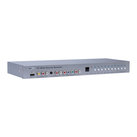
PANEL LAYOUT Back Panel... -
Page 10: Panel Descriptions
PANEL DESCRIPTIONS Front Panel HDMI In 1 Connect a Hi-Def source device to this port using an HDMI cable. Composite / Audio In 1 Connect a Composite source to this input using 3x RCA cables. S-Video / Audio In 1 Connect an S-Video source to this input using an S-Video cable and 2x RCA cables. - Page 11 PANEL DESCRIPTIONS 13 Component / Audio In 1 Connect a Component source to this input using 5x RCA cables. 14 S-Video / Audio In 2 Connect an S-Video source to this input using an S-Video cable and 2x RCA cables. 15 PC / Audio In Connect a VGA cable to the DB-15 connector.
-
Page 12: Ir Remote Control
IR REMOTE CONTROL Layout and Descriptions LED Indicator This LED will be activated momentarily each time a button is pressed. CV1, CV2 Selects the Composite 1 (CV1) or Composite 2 (CV2) input. Selects the VGA input. HD1, HD2, HD3 Selects the HDMI 1 (HD1), HDMI 2 (HD2), or HDMI 3 (HD3) input. CO1, CO2 Selects the Component 1(CO1) or Component 2 (CO2) input. -
Page 13: Installing The Battery
IR REMOTE CONTROL Installing the Battery The Remote Control unit ships with two batteries. One battery is required for operation and the other battery is a spare. Remove the battery cover on the back of the IR Remote Control unit. Insert the included battery into the open battery slot. -
Page 14: Connecting The Tv Multi Format Switcher
CONNECTING THE TV MULTI FORMAT SWITCHER How to Connect the TV Multi Format Switcher Connect the HDMI output on the TV Multi Format Switcher to the display using the supplied HDMI cable. Connect up to three HDMI sources to the HDMI inputs. Connect analog audio/video sources to the TV Multi Format Switcher using the following cables: •... -
Page 15: Operating The Tv Multi Format Switcher
OPERATING THE TV MULTI FORMAT SWITCHER Selecting the Input Source • To select an input source, press any one of the front panel buttons. In the example below, the HDMI1 button has been pressed. LED indicates that HDMI In 1 is the current input source. -
Page 16: Setting The Ir Channel
OPERATING THE TV MULTI FORMAT SWITCHER Setting the IR channel After the TV Multi Format Switcher is powered, press and hold the CV1 and CV2 simultaneously. After a few seconds, the power LED will begin to fl ash rapidly. Flashing power LED The current IR channel will be indicated by the CV1 and CV2 buttons on the front panel. - Page 17 OPERATING THE TV MULTI FORMAT SWITCHER Once the TV Multi Format Switcher is set to the correct IR channel, simultaneously press and hold the CV1 and CV2 buttons to reboot the Switcher. All of the front panel LED switching indicators will glow bright blue momentarily, after which the Switcher will be ready for use.
-
Page 18: Rs-232 Serial Control
RS-232 SERIAL CONTROL 5 4 3 2 1 1 2 3 4 5 9 8 7 6 6 7 8 9 Only Pins 2 (RX), 3 (TX), and 5 (Ground) are used on the RS-232 serial interface RS232 Settings Bits per second ....................9600 Data bits ........................ -
Page 19: Rs-232 Commands
RS-232 COMMANDS Commands Command RS-232 return value Description HELP Lists all commands Lists all commands S POWER 0 POWER OFF Power OFF S POWER 1 POWER ON Power ON S SOURCE 0 SOURCE HDMI1 Switch to HDMI In 1 S SOURCE 1 SOURCE HDMI2 Switch to HDMI In 2 S SOURCE 2... -
Page 20: Rack Mount Installation
RACK MOUNT INSTALLATION Rack mount ears are provided for installation of this unit into a 1U rack mount space. Locate the side screws on the unit. Remove the front 2 screws that are located closest to the front of the unit. Using the removed screws, screw the rack mounting bracket into the unit. -
Page 21: Specifi Cations
SPECIFICATIONS Maximum Pixel Clock ................225 MHz Video Amplifi er Bandwidth ............... 350 MHz Video Output Connector ........(1) HDMI Type A, 19-pin, female Video Input Connectors ........(3) HDMI Type A 19-pin, female (2) Component (3x RCA) (2) Composite, RCA (1) HD-15, female RS-232 Remote Control Port............. -
Page 22: Warranty
Gefen warrants the equipment it manufactures to be free from defects in material and workmanship. If equipment fails because of such defects and Gefen is notifi ed within two (2) years from the date of shipment, Gefen will, at its option, repair or replace the equipment, provided that the equipment has not been subjected to mechanical, electrical, or other abuse or modifi... - Page 24 Rev A9 20600 Nordhoff St., Chatsworth CA 91311 1-800-545-6900 818-772-9100 fax: 818-772-9120 www.gefen.com support@gefen.com This product uses UL or CE listed power supplies.
Need help?
Do you have a question about the EXT-TV-MFS and is the answer not in the manual?
Questions and answers