Gefen EXT-USB-400FON User Manual
Usb 400 fo
Hide thumbs
Also See for EXT-USB-400FON:
- User manual (19 pages) ,
- User manual (21 pages) ,
- User manual (19 pages)
Table of Contents
Advertisement
Quick Links
Download this manual
See also:
User Manual
Advertisement
Table of Contents

Subscribe to Our Youtube Channel
Related Manuals for Gefen EXT-USB-400FON


Summary of Contents for Gefen EXT-USB-400FON
- Page 1 ® USB 400 FO EXT-USB-400FON User Manual www.gefen.com...
- Page 3 Notice Gefen, LLC reserves the right to make changes in the hardware, packaging, and any accompanying documentation without prior written notice. USB 400 FO is a trademark of Gefen, LLC All trademarks are the property of their respective owners.
-
Page 4: Table Of Contents
CONTENTS Introduction Operation Notes Features Sender Unit Panel Layout Sender Unit Panel Descriptions Receiver Unit Panel Layout Receiver Unit Panel Descriptions Connecting And Operating The USB 400 FO Extender Wiring Diagram Troubleshooting The USB 400FO Extender 14 Specifications 15 Warranty... -
Page 5: Introduction
Congratulations on your purchase of the USB 400 FO. Your complete satisfaction is very important to us. Gefen Gefen delivers innovative, progressive computer and electronics add-on solutions that harness integration, extension, distribution and conversion technologies. Gefen’s reliable, plug-and-play products supplement cross-platform computer systems, professional audio/video environments, and HDTV systems of all sizes with hard-working solutions that are easy to implement and simple to operate. -
Page 6: Operation Notes
OPERATION NOTES READ THESE NOTES BEFORE INSTALLING OR OPERATING THE USB 400 FO This equipment provides outstanding extension facilities for any device or USB application that requires a peripheral connection over a distance, such as a USB camera or USB hard drive, keyboard, and mouse. The USB 400 FO works like a USB hub with extension capabilities over a distance of up to 1,640 feet. -
Page 7: Features
Ideal as optical isolation from over-voltage and static electricity • Supports High Speed devices up to 480Mbps Package Includes (1) Gefen USB-400FO Sender Unit (1) Gefen USB-400FO Receiver Unit (1) 6 ft. USB Cable (A-B) (2) 5V DC Power Supplies... -
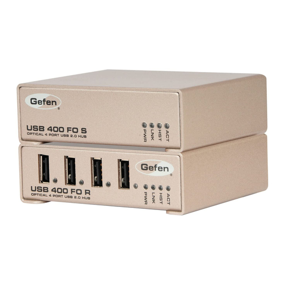
Page 8: Sender Unit Panel Layout
SENDER UNIT PANEL LAYOUT Front Panel 1 2 3 4 Back Panel... -
Page 9: Sender Unit Panel Descriptions
SENDER UNIT PANEL DESCRIPTIONS Power Indicator LED turns bright blue when power is supplied. Link Indicator This LED turns bright green when a valid ExtremeUSB® link is established between the Sender Unit and Receiver Unit. Host Indicator This LED turns bright green when the USB 400 FO system is properly enumerated on the host PC. -
Page 10: Receiver Unit Panel Layout
RECEIVER UNIT PANEL LAYOUT Front Panel 3 4 5 6 Back Panel... -
Page 11: Receiver Unit Panel Descriptions
RECEIVER UNIT PANEL DESCRIPTIONS USB Port (1-4) USB device input ports. USB Indicator (1-4) This LED indicates when a USB device is connected to the Device Port. Solid green when device is plugged in and active. Off when device is in a suspend mode or Receiver unit is powered off. -
Page 12: Connecting And Operating The Usb 400 Fo Extender
500mA to the unit, connect the secondary (included) 5V power supply to the Sender unit. Wiring Diagram for the USB 400 FO Extender FIBER OPTIC LC-LC CABLE (Up to 1640 ft.) USB CABLE USB Peripheral Receiver USB Peripheral Computer Sender USB Peripheral USB Peripheral EXT-USB-400FON... - Page 13 TROUBLESHOOTING Verifying Installation on PC or Macintosh Computers 1. For Windows users (2000, XP, Vista, Windows 7), open the Device Manager to confirm that the USB 400 FO has installed correctly. Expand the entry for Universal Serial Bus controllers by clicking the + sign. If the USB 400 FO has been installed correctly, you should find it listed as a “Generic USB Hub”.
-
Page 14: Troubleshooting The Usb 400Fo Extender
TROUBLESHOOTING THE USB 400 FO EXTENDER PROBLEM CAUSE SOLUTION Link LEDs on Sender unit There is no connection 1. Ensure that a multi- and Receiver unit are off. between the Sender unit mode fiber optic cable and Receiver unit. with crossover is connected between the Sender and Receiver units. - Page 15 TROUBLESHOOTING THE USB 400 FO EXTENDER PROBLEM CAUSE SOLUTION USB 400 FO units were The Receiver unit is 1. Recover/Resume the working, but the Host in suspend mode. The operating system from LED on Sender/Receiver operating system may Suspend/Standby mode units are suddenly put the USB 400 FO in (see your operating...
- Page 16 TROUBLESHOOTING THE USB 400 FO EXTENDER PROBLEM CAUSE SOLUTION USB device A USB device must have 1. Install the required is attached to the appropriate driver USB device driver on the Receiver USB installed on the computer computer operating system port but Receiver operating system prior to attaching the USB...
-
Page 17: Specifications
SPECIFICATIONS USB Maximum Transfer Rate..............480Mbps USB Connector (Sender).................(1) Type B USB Connector (Receiver) ..............(4) Type A Link Connector................(2) Fiber, Type LC Power Supply (Sender / Receiver.)..........5V DC, Locking Operating temperature range..............0 - 50 °C Dimensions (Sender / Receiver)..........4” W x 3” D x 1.25” H Shipping Weight....................2 lbs Range......1640ft. -
Page 18: Warranty
If equipment fails because of such defects and Gefen is notified within two (2) years from the date of shipment, Gefen will, at its option, repair or replace the equipment, provided that the equipment has not been subjected to mechanical, electrical, or other abuse or modifications. - Page 20 Rev A7 20600 Nordhoff St., Chatsworth CA 91311 1-800-545-6900 818-772-9100 fax: 818-772-9120 www.gefen.com support@gefen.com This product uses UL listed power supplies.
Need help?
Do you have a question about the EXT-USB-400FON and is the answer not in the manual?
Questions and answers