
Related Manuals for GE 45609


Summary of Contents for GE 45609
- Page 1 45609/45614 Z-Wave ® Certified Wireless Lighting Control On/Off Relay Switch and 3-Way Switch Kit Control the On/Off status of permanently installed lighting, fans and more! ©2009 Jasco www.easyzwave.com Made in China...
- Page 2 On/Off Relay Switch and 3-Way Switch Kit Introduction Thank you for your purchase of a GE Z-Wave® control device. Z-Wave technology is designed to automate lighting/home control and provide easy remote operation of all your Z-Wave enabled de- vices. The GE Z-Wave product family includes a variety of devices to control lighting in your home.
-
Page 3: Wireless Range
1. Assign Z-Wave controlled appliances to device numbers 10 – 18 on the GE remote. The likelihood of unintentionally turn- ing on the appliance will be reduced significantly because the “Shift” button will need to be pressed before pressing device numbers 10-18. -
Page 4: 3-Way Circuits
Things to consider regarding RF range: • Each wall or obstacle (i.e.: refrigerator, big screen TV, etc.) between the remote or Z-Wave device and the destination device will reduce the maximum range by approximately 25-30%. • Brick, tile or concrete walls block more of the RF signal than walls made of wooden studs and plasterboard (drywall). -
Page 5: Installation
One of the ways to wire a two-switch/one-load circuit is to route the incoming power through the first switch, then to the second switch and then to the load. Although very common and by no means a standard, it is the easiest to convert to Z-Wave control. With this type of circuit, Switch 1 is replaced by the Z-Wave auxiliary switch and Switch 2 is replaced with the primary Z-Wave switch. -
Page 6: 3-Way Wiring Schematic
3-Way Wiring Schematic using one 45609 and one 45610 White (Neutral) Black Traveler - Colored (Not Green) (Load) Z-Wave Z-Wave 45610 45609 Green (Ground) Black (Line/Hot) 4-Way Wiring Schematic using one 45609 and two 45610’s Traveler - Colored (Not Green) Z-Wave 45610 White (Neutral) -
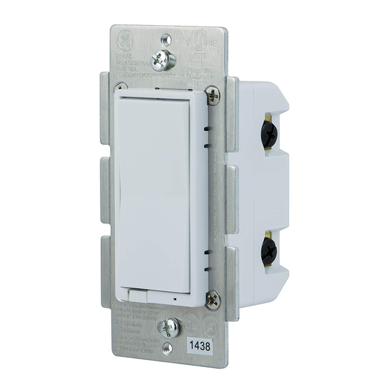
Page 7: Single/Dual/Triple Gang Boxes
Single, Dual and Triple Gang Boxes Tabs Tabs When installing the 45609 in multiple gang boxes it may be necessary to break off one or both of the scored tabs on the front yoke. This does not affect the electrical rating of the 45609. - Page 8 11. OPTIONAL for 3 or 4-way control): Connect the Traveler wire (usually Red) to the screw terminal marked TRAVELER. The other end of this Traveler wire connects to the TRAVELER screw terminal on the 45610 Auxiliary Switch. See the following section for information about wiring the 45610 Auxiliary Switch.
-
Page 9: Air Gap Switch
• LED indicates switch location in a dark room BASIC OPERATION Remote Control GE Z-Wave remotes provide control of an Individual device, Groups of devices and Scenes. Other brands of Z-Wave Certified remotes may not offer as much flexibility in how you can set up your lighting control network. -
Page 10: Advanced Operation
ADVANCED OPERATION The following Advanced Operation parameters require that you have an advanced controller like the GE model 45601 LCD remote. Advanced remotes from other manufacturers may also be able to change these settings; however, basic remotes do not have this capability. -
Page 11: Invert Switch
Z-Wave certified products, your controller must include the appropriate device classifications in order to control non-light- ing Z-wave devices. As an example, the GE 45600 basic remote is designed only for controlling Z-Wave devices using the lighting control classification. The GE 45601 deluxe remote with LCD read- out can control other Z-Wave certified devices like thermostats as well as lighting. - Page 12 U2Z45609 The Federal Communication Commission Radio Frequency Inter- ference Statement includes the following paragraph: The equipment has been tested and found to comply with the limits for a Class B Digital Device, pursuant to part 15 of the FCC Rules. These limits are designed to provide reasonable protection against harmful interference in a residential installation.
-
Page 13: Specifications
SPECIFICATIONS ZW4001 Power: 120 VAC, 60 Hz. Signal (Frequency): 908.42 MHz. Maximum Loads: 600W, incandescent, ½ HP Motor or 1800W (15A) Resistive Range: Up to 100 feet line of sight between the Wireless Controller and the closest Z-Wave receiver module. Operating Temperature Range: 32-104°...
Need help?
Do you have a question about the 45609 and is the answer not in the manual?
Questions and answers