Table of Contents
Advertisement
Quick Links
INSTALLATION AND MAINTENANCE INSTRUCTIONS
2151 Low Profile
Photoelectronic Plug-in
Smoke Detector
Specifications
Size
Height:
Diameter:
Weight:
Operating Temperature Range:
Operating Humidity Range:
Latching Alarm:
Before Installing
Please thoroughly read the System Sensor manual A05-
1003, Applications Guide for System Smoke Detectors,
which provides detailed information on detector spacing,
placement, zoning, wiring, and special applications. Copies
of this manual are available from System Sensor.
NOTICE: This manual should be left with the owner/user
of this equipment.
IMPORTANT: The detector used with this base must be
tested and maintained regularly following NFPA 72 require-
ments. The detector used with this base should be cleaned
at least once a year.
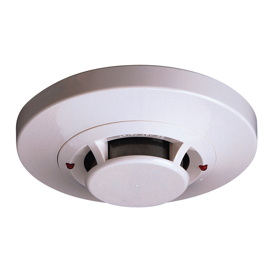
General Description
The 2151 low-profile photoelectronic detector uses a state-
of-the-art optical sensing chamber. This detector is designed
to provide open area protection and to be used with com-
patible UL listed control panels only. The capability of plug-
ging this detector into a variety of special bases makes it
more versatile than equivalent direct-wired models.
Two LEDs on each detector provide local 360° visible
alarm indication. They flash every ten seconds indicating
that power is applied and the detector is working properly.
The LEDs latch on in alarm. Remote LED annunciator
capability is standard and may be implemented through
an optional accessory RA400Z. The alarm can be reset
only by a momentary power interruption. This detector
may be tested by activating the internal reed switch with
a magnet.
Base Selection And Wiring Guide
Refer to the installation instructions for the Plug-in
Detector Bases for base selection and wiring instructions.
System Sensor has a variety of detector bases available for
D100-04-00
1.7 inches (43 mm)
4.0 inches (101 mm)
3.6 oz. (102 g)
0°C to 49°C (32°F to 120°F)
10% to 93% Relative Humidity noncondensing
Reset by momentary power interruption.
1
3825 Ohio Avenue, St. Charles, Illinois 60174
this smoke detector, including 2-wire applications with and
without relays and/or current limiting resistors, 4-wire and
120VAC applications.
All bases are provided with screw terminals for power,
ground, remote annunciator connections and relay contact
connections, if applicable. The electrical ratings for each
detector-base combination are also included in the base
installation instructions.
Installation
NOTE: All wiring must conform to applicable local codes,
ordinances, and regulations.
NOTE: Verify that all detector bases are installed, that
the initiating-device circuits have been tested, and
that the wiring is correct. (Refer to detector base
manual for testing procedure.)
Remove power from initiating-device circuits before install-
ing detectors.
1. Install detectors:
a. Place the detector into the detector base.
b. Turn the detector clockwise until the detector drops
into place.
c. Continue turning detector clockwise to lock it in
place.
2. Tamper Resistance: The detector bases can be made tam-
per resistant. When capability is enabled, detectors can-
not be removed from the base without the use of a tool.
See the detector base installation manual of the detector
base for details in using this capability.
3. After all detectors have been installed, apply power to
the control unit.
1-800-SENSOR2, FAX: 630-377-6495
www.systemsensor.com
WARNING
I56-581-07R
Advertisement
Table of Contents

Related Manuals for System Sensor 2151


Summary of Contents for System Sensor 2151
- Page 1 INSTALLATION AND MAINTENANCE INSTRUCTIONS 2151 Low Profile Photoelectronic Plug-in 3825 Ohio Avenue, St. Charles, Illinois 60174 Smoke Detector 1-800-SENSOR2, FAX: 630-377-6495 www.systemsensor.com Specifications Size Height: 1.7 inches (43 mm) Diameter: 4.0 inches (101 mm) Weight: 3.6 oz. (102 g) Operating Temperature Range: 0°C to 49°C (32°F to 120°F) Operating Humidity Range: 10% to 93% Relative Humidity noncondensing Latching Alarm: Reset by momentary power interruption. Before Installing this smoke detector, including 2-wire applications with and Please thoroughly read the System Sensor manual A05- without relays and/or current limiting resistors, 4-wire and 1003, Applications Guide for System Smoke Detectors, 120VAC applications.
- Page 2 4. Test the detector using the magnet as described under A. Test Magnet (p/n M02-04-01 or M02-09-00) TESTING. 1. Place the magnet against the cover in the location 5. Reset the detector at the system control panel. designated by the raised mark to activate the test fea- 6. Notify the proper authorities that the system is back on ture (see Figure 1). line. 2. The LEDs should latch ON within 5 seconds indicat- ing alarm and annunciating the panel. CAUTION Dust covers are an effective way to limit the entry of dust B. Test Module ( MOD400R) into smoke detector sensing chambers. However, they may Use the MOD400R with a DMM or voltmeter to check not completely prevent airborne dust particles from enter- the detector sensitivity as described in the MOD400R ing the detector. Therefore, System Sensor recommends the...
- Page 3 Figure 2: 1. Remove the detector cover by prying away the four side tabs with a small-bladed screwdriver, and then SENSOR COVER pulling the cover from the base. 2. Vacuum the screen carefully without removing it. If further cleaning is required continue with Step 3, oth- erwise skip to Step 8. 3. Remove the screen assembly by pulling it straight out (see Figure 2). 4. Remove the sensing chamber cover by pulling it straight out.
- Page 4 Please refer to insert for the Limitations of Fire Alarm Systems Three-Year Limited Warranty Department, RA #__________, 3825 Ohio Avenue, St. Charles, IL 60174. System Sensor warrants its enclosed smoke detector to be free from Please include a note describing the malfunction and suspected cause defects in materials and workmanship under normal use and service for a of failure. The Company shall not be obligated to repair or replace units period of three years from date of manufacture. System Sensor makes no...
Need help?
Do you have a question about the 2151 and is the answer not in the manual?
Questions and answers