Table of Contents
Advertisement
Quick Links
INSTALLATION AND MAINTENANCE INSTRUCTIONS
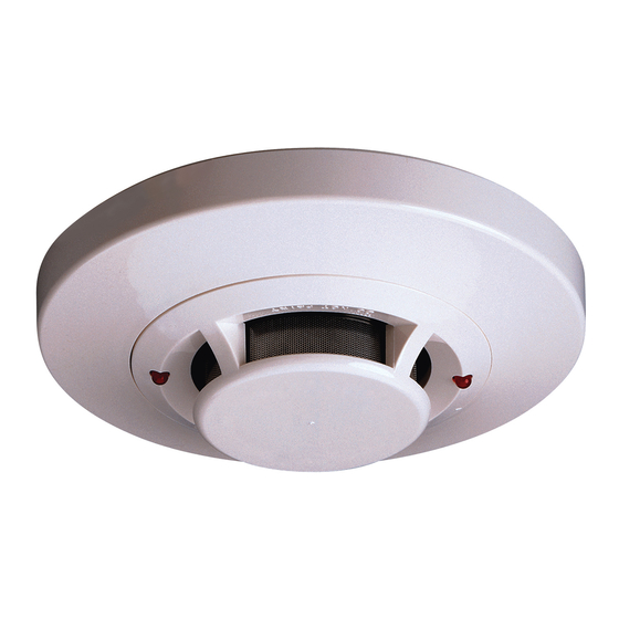
2151/2151T Low Profile
Photoelectronic Plug-in
Smoke Detectors
Specifications
Size
Height:
Diameter:
Weight:
Operating Temperature Range:
Operating Humidity Range:
Heat Sensor (2151T only):
Operating Voltage:
Standby Current:
Latching Alarm:
Before Installing
Please thoroughly read the System Sensor manual A05-
1003, Applications Guide for System Smoke Detectors,
which provides detailed information on detector spacing,
placement, zoning, wiring, and special applications. Copies
of this manual are available from System Sensor.
NOTICE: This manual should be left with the owner/user
of this equipment.
IMPORTANT: The detector must be tested and maintained
regularly following NFPA 72 requirements. The detector
should be cleaned at least once a year.
General Description
The 2151 low-profile photoelectronic detector uses a state-
of-the-art optical sensing chamber. This detector is de-
signed to provide open area protection and to be used with
compatible UL listed control panels only. The capability of
plugging this detector into a variety of special bases makes
it more versatile than equivalent direct-wired models.
Two LEDs on each detector provide local 360° visible alarm
indication. They flash every five seconds indicating that
power is applied and the detector is working properly. The
LEDs latch on in alarm. LEDs will be off when a trouble
condition exists indicating that the detector sensitivity is
outside the listed limit. Remote LED annunciator capability
is standard and may be implemented through an optional
accessory RA400Z. The alarm can be reset only by a mo-
mentary power interruption. This detector may be tested
by activating the internal reed switch with a magnet.
Base Selection And Wiring Guide
Refer to the installation instructions for the Plug-in Detec-
tor Bases for base selection and wiring instructions. Sys-
tem Sensor has a variety of detector bases available for
this smoke detector, including 2-wire applications with and
without relays and/or current limiting resistors, 4-wire and
120VAC applications.
D100-101-00
2.0 inches (51 mm) installed in B401 Base
4.1 inches (104 mm) installed in B401 Base
6.1 inches (155 mm) installed in B110LP Base
3.1 oz. (88 g)
0°C to 49°C (32°F to 120°F); 2151,0°C to 38°C (32°F to 100°F); 2151T
10% to 93% Relative Humidity noncondensing
135°F Fixed Temperature Electronic Thermistor
8.5 to 35VDC
120µA
Reset by momentary power interruption.
All bases are provided with screw terminals for power,
ground, remote annunciator connections and relay contact
connections, if applicable. The electrical ratings for each
detector-base combination are also included in the base in-
stallation instructions.
Installation
NOTE: All wiring must conform to applicable local codes,
ordinances, and regulations.
NOTE: Verify that all detector bases are installed, that
the initiating-device circuits have been tested, and that
the wiring is correct. (Refer to detector base manual for
testing procedure.)
Remove power from initiating-device circuits before install-
ing detectors.
1. Install detectors:
2. Tamper Resistance: The detector bases can be made
3. After all detectors have been installed, apply power to
4. Test the detector using the magnet as described under
5. Reset the detector at the system control panel.
6. Notify the proper authorities that the system is back on line.
1
3825 Ohio Avenue, St. Charles, Illinois 60174
WARNING
a. Place the detector into the detector base.
b. Turn the detector clockwise until the detector drops
into place.
c. Continue turning detector clockwise to lock it in place.
tamper resistant. When capability is enabled, detectors
cannot be removed from the base without the use of a
tool. See the detector base installation manual of the
detector base for details in using this capability.
the control unit.
TESTING.
1-800-SENSOR2, FAX: 630-377-6495
www.systemsensor.com
I56-2806-003R
Advertisement
Table of Contents

Related Manuals for System Sensor 2151


Summary of Contents for System Sensor 2151
- Page 1 6.1 inches (155 mm) installed in B110LP Base Weight: 3.1 oz. (88 g) Operating Temperature Range: 0°C to 49°C (32°F to 120°F); 2151,0°C to 38°C (32°F to 100°F); 2151T Operating Humidity Range: 10% to 93% Relative Humidity noncondensing Heat Sensor (2151T only): 135°F Fixed Temperature Electronic Thermistor...
- Page 2 RDR instruction manual for operating details. not completely prevent airborne dust particles from enter- C. Aerosol Generator (Gemini 501) ing the detector. Therefore, System Sensor recommends the Set the generator to represent 4% to 5%/ft. obscuration removal of detectors before beginning construction or other as described in the Gemini 501 Manual.
- Page 3 Cleaning Figure 2: Before removing the detector, notify the proper authorities that the smoke detector system is undergoing maintenance and will be temporarily out of service. Disable the zone or sys- Sensor tem undergoing maintenance to prevent unwanted alarms. Cover 1.
- Page 4 Please refer to insert for the Limitations of Fire Alarm Systems Three-Year Limited Warranty System Sensor warrants its enclosed smoke detector to be free from defects in ma- postage prepaid to: System Sensor, Repair Department, RA #__________, 3825 Ohio terials and workmanship under normal use and service for a period of three years Avenue, St.
Need help?
Do you have a question about the 2151 and is the answer not in the manual?
Questions and answers