Table of Contents
Advertisement
Quick Links
Installation AND MAINTENANCE INSTRUCTIONS
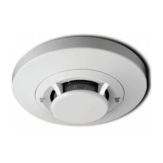
2151A Low Profile
Photoelectronic Plug-in
Smoke Detector
Specifications
Size
Height:
Diameter:
Weight:
Operating Voltage:
Max. Avg. Standby Current:
Operating Temperature Range:
Operating Humidity Range:
Latching Alarm:
Before Installing
Please thoroughly read the System Sensor manual I56-
407, Guide for Proper Use of System Smoke Detectors,
which provides detailed information on detector spacing,
placement, zoning, wiring, and special applications. Cop-
ies of this manual are available at no charge from System
Sensor. Please also refer to CAN/ULC-S524-M91, Stan-
dard for the Installation of Fire Alarm Systems, and CEC
Part 1, Sec. 32.
NOTICE: This manual should be left with the owner/user
of this equipment.
IMPORTANT: The detector used with this base must be
tested and maintained regularly following CAN/ULC-S536
requirements. The detector used with this base should be
cleaned at least once a year.
General Description
The 2151A low-profile photoelectronic detector uses a
state-of-the-art optical sensing chamber. This detector
is designed to provide open area protection and to be
used with compatible ULC-listed control panels only. The
capability of plugging the detector into a variety of special
bases makes it more versatile than equivalent direct-wired
models.
Adapter Base Selection Guide
Base Model
Loop
Number
Type
B110LP
2-wire*
B112LPA
4-wire
B114LPA
4-wire
B116LPA
2-wire*
B401
2-wire*
*Functionality contingent on panel compatibility **Must be limited by control panel †Flangeless base
Relay Contact Ratings:
Resistive or Inductive (60% power factor) load.
Form A:
2.0A at 30 VAC/DC
Form C:
0.6A at 110VDC, 2.0A at 30VDC - 1.0A at 125VAC, 2.0A at 30VAC
D100-04-00
1.7 inches (43 mm)
4.0 inches (101 mm)
3.6 oz. (102 g)
10 to 32 VDC
120uA
0° to 49°C (32° to 120°F)
10% to 93% Relative Humidity noncondensing
Reset by momentary power interruption.
Current
Limit Resistor
No
Yes
Yes
Form A&C + A Supy.
No
No
1
6581 Kitimat Rd., Unit #6, Mississauga, Ontario, L5N 3T5
Two LEDs on each detector provide local 360° visible
alarm indication. They flash every ten seconds indicating
that power is applied and the detector is working properly.
The LEDs latch on in alarm. Remote LED annunciator
capability is standard and may be implemented through
an optional accessory RA400ZA. The alarm can be reset
only by a momentary power interruption. These detectors
may be tested by activating the internal reed switch with a
magnet.
Base Selection And Wiring Guide
Refer to the installation instructions for the Plug-in De-
tector Bases for base selection and wiring instructions.
System Sensor has a variety of detector bases available
for this smoke detector, including 2-wire applications with
and without relays and/or current limiting resistors, 4-wire
and 120VAC applications ( see list below ).
All bases are provided with screw terminals for power,
ground, remote annunciator connections and relay con-
tact connections, if applicable. The electrical ratings for
each detector-base combination are also included in the
base installation instructions.
Alarm
Nominal
Contact Type
Voltage
—
12/24VDC
Form A&C
120VAC
Form C
—
12/24VDC
1-800-SENSOR2, FAX: 905-812-0771
www.systemsensor.ca
Current Draw
on Alarm (mA)
10–100**
24VDC
14–39
75 mA AC Max
24VDC
12–100**
10–100**
I56-1015-000
Advertisement
Table of Contents

Related Manuals for System Sensor 2151A


Summary of Contents for System Sensor 2151A
- Page 1 Base Selection And Wiring Guide of this equipment. Refer to the installation instructions for the Plug-in De- IMPORTANT: The detector used with this base must be tector Bases for base selection and wiring instructions. tested and maintained regularly following CAN/ULC-S536 System Sensor has a variety of detector bases available requirements. The detector used with this base should be for this smoke detector, including 2-wire applications with cleaned at least once a year. and without relays and/or current limiting resistors, 4-wire General Description and 120VAC applications ( see list below ). The 2151A low-profile photoelectronic detector uses a All bases are provided with screw terminals for power, state-of-the-art optical sensing chamber. This detector ground, remote annunciator connections and relay con- is designed to provide open area protection and to be tact connections, if applicable. The electrical ratings for used with compatible ULC-listed control panels only. The each detector-base combination are also included in the capability of plugging the detector into a variety of special base installation instructions. bases makes it more versatile than equivalent direct-wired models. Adapter Base Selection Guide...
- Page 2 Be sure to remove the dust covers from any sensors that WARNING were left in place during construction as part of returning Remove power from initiating-device circuits before in- the system to service. stalling detectors. Testing 1. Install detectors: Before testing, notify the proper authorities that the a. Place the detector into the detector base. smoke detector system is undergoing maintenance and b. Turn the detector clockwise until the detector drops will temporarily be out of service. Disable the zone or into place. system undergoing maintenance to prevent unwanted c. Continue turning detector clockwise to lock it in alarms. Detectors must be tested after installation and as place. part of periodic maintenance. Test the 2151A as follows: 2. Tamper Resistance: The detector bases can be made tamper resistant. When capability is enabled, detectors NOTE: Before testing the detector, check to ensure the cannot be removed from the base without the use of a the LEDs blink. If they do not, the detector has tool. See the detector base installation manual of the lost power (check the wiring) or it is defective detector base for details in using this capability. (return it for repair). 3. After all detectors have been installed, apply power to the control unit. A. Test Magnet (System Sensor model no. M02-04-01) 4. Test the detector using the magnet as described under 1. Place the magnet against the cover in the location TESTING. designated by the raised mark to activate the test 5. Reset the detector at the system control panel. feature (see Figure 1).
- Page 3 Figure 2: B. Test Module ( MOD400R) Use the MOD400R with a DMM or voltmeter to check REMOVABLE COVER the detector sensitivity as described in the MOD400R manual. C. Aerosol Generator (Gemini 501) Set the generator to represent 4% to 5%/ft. obscura- tion as described in the Gemini 501 Manual. Using the REMOVABLE bowl- shaped applicator, apply aerosol until unit alarms. SCREEN Notify the proper authorities that the system is back on line. VANED Detectors that fail these tests should be cleaned as CHAMBER described under MAINTENANCE and retested. If the detectors still fail these tests, they should be returned for repair. Maintenance It is recommended that the detector be removed from A78-2456-00 its mounting base to facilitate cleaning. The detector is cleaned as follows: NOTE: Before removing the detector, notify the proper authorities that the smoke detector system is undergoing maintenance and will be temporarily out of service. Disable the zone or system under- going maintenance to prevent unwanted alarms. 1. Remove the detector cover by prying away the four side tabs with a small-bladed screwdriver, and then pulling the cover from the base. 2. Vacuum the screen carefully without removing it. If further cleaning is required continue with Step 3, oth- erwise skip to Step 6. 3. Remove the screen assembly by pulling it straight out (see Figure 2). Vacuum the inside.
- Page 4 Please refer to insert for the Limitations of Fire Alarm Systems Three-Year Limited Warranty System Sensor warrants its enclosed smoke detector to be free from Department, RA #__________, 6581 Kitimat Rd., Unit #6, Mississauga, defects in materials and workmanship under normal use and service for a Ontario, L5N 3T5. Please include a note describing the malfunction and period of three years from date of manufacture. System Sensor makes no suspected cause of failure. The Company shall not be obligated to repair other express warranty for this smoke detector. No agent, representative, or replace units which are found to be defective because of damage, unreasonable use, modifications, or alterations occurring after the date dealer, or employee of the Company has the authority to increase or alter the obligations or limitations of this Warranty. The Company’s obligation...
Need help?
Do you have a question about the 2151A and is the answer not in the manual?
Questions and answers