Table of Contents
Advertisement
Quick Links
Advertisement
Chapters
Table of Contents

Related Manuals for South bend MODEL SB1016


Summary of Contents for South bend MODEL SB1016
- Page 1 18" & 60" EVS TOOLROOM LATHES MODEL SB1016 - 220V Three Phase MODEL SB1036 - 440V Three Phase OWNER'S MANUAL Hundreds of Thousands of Lathes Sold With a Tradition of uality Since 1906! © August, 2010 by South Bend Lathe Co. For Machines Mfg.
- Page 2 Scope of Manual This manual helps the reader understand the machine, how to prepare it for operation, how to control it during operation, and how to keep it in good working condition. We assume the reader has a basic understanding of how to operate this type of machine, but that the reader is not familiar with the controls and adjustments of this specific model.
-
Page 3: Table Of Contents
Table of Contents INTRODUCTION ............3 OPERATION ............31 About These Machines......... 3 Operation Overview ........... 31 ............. 3 Description of Controls & Components .... 32 Foreword ............3 ........... 32 Capabilities Main Power Control .............. 3 ..........32 Features Headstock Controls Identification ............ - Page 4 Power Feed ............54 ELECTRICAL ............91 .......... 54 Electrical Safety Instructions ......91 Power Feed Controls Threading ............56 Wiring Overview ..........92 ..........56 SB1016/36 Component Location Index ..... 93 Power Feed Lever ..........56 SB1016/36 Electrical Box Wiring ...... 94 Half Nut Lever ......
-
Page 5: Introduction
For Machines Mfg. Since 7/09 I N T R O D U C T I O N Model SB1016/SB1036 INTRODUCTION About These Machines Foreword Features "The screw cutting engine lathe is the oldest and As the name implies, these lathes feature EVS most important of machine tools and from it all (Electronic Variable Speed) spindle control, other machine tools have been developed. -
Page 6: Identification
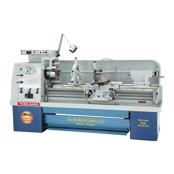
Model SB1016/SB1036 I N T R O D U C T I O N For Machines Mfg. Since 7/09 Identification Figure 1. The 18" x 60" Variable Speed Toolroom Lathe (EVS). A. Control Panel Half Nut Lever B. Chuck Guard w/Safety Switch Q. - Page 7 For Machines Mfg. Since 7/09 I N T R O D U C T I O N Model SB1016/SB1036...
- Page 8 Model SB1016/SB1036 I N T R O D U C T I O N For Machines Mfg. Since 7/09...
- Page 9 For Machines Mfg. Since 7/09 I N T R O D U C T I O N Model SB1016/SB1036...
- Page 10 Model SB1016/SB1036 I N T R O D U C T I O N For Machines Mfg. Since 7/09...
- Page 11 For Machines Mfg. Since 7/09 I N T R O D U C T I O N Model SB1016/SB1036...
- Page 12 Model SB1016/SB1036 I N T R O D U C T I O N For Machines Mfg. Since 7/09 -10-...
-
Page 13: Safety
For Machines Mfg. Since 7/09 S A F E T Y Model SB1016/SB1036 SAFETY Understanding Risks of Machinery Operating all machinery and machining equipment can be dangerous or relatively safe depending on how it is installed and maintained, and the operator's experience, common sense, risk awareness, working conditions, and use of personal protective equipment (safety glasses, respirators, etc.). - Page 14 Model SB1016/SB1036 S A F E T Y For Machines Mfg. Since 7/09 Entanglement: Loose clothing, gloves, 11. Chuck Keys or Adjusting Tools: Tools used neckties, jewelry or long hair may to adjust spindles, chucks, or any moving/ get caught in moving parts, causing rotating parts will become dangerous entanglement, amputation, crushing, projectiles if left in place when the machine...
-
Page 15: Additional Metal Lathe Safety
For Machines Mfg. Since 7/09 S A F E T Y Model SB1016/SB1036 Additional Metal Lathe Safety Clearing Chips: Metal chips can easily cut Speed Rates: Operating the lathe at the bare skin—even through a piece of cloth. wrong speed can cause nearby parts to break Avoid clearing chips by hand or with a rag. -
Page 16: Preparation
Model SB1016/SB1036 P R E P A R A T I O N For Machines Mfg. Since 7/09 PREPARATION Preparation Overview Things You'll Need The purpose of the preparation section is to help To complete the preparation process, you will you prepare your machine for operation. -
Page 17: Power Supply Requirements
For Machines Mfg. Since 7/09 P R E P A R A T I O N Model SB1016/SB1036 Circuit Information Power Supply A power supply circuit includes all electrical Requirements equipment between the main breaker box or fuse panel in your building and the incoming power connections inside the machine. -
Page 18: Grounding Requirements
Model SB1016/SB1036 P R E P A R A T I O N For Machines Mfg. Since 7/09 Circuit Requirements for 220V Correcting Phase Polarity (Model SB1016) (Yaskawa Drive) This sub-section is only provided for This machine is prewired to operate on a 220V troubleshooting by a qualified electrician. - Page 19 For Machines Mfg. Since 7/09 P R E P A R A T I O N Model SB1016/SB1036 — If one or more pump motors do not pump or rotate in the incorrect direction, locate Variable Frequency Master Power the master power switch on the lathe, Drive (Figure 3) Switch (Figure 4) and swap any two of the L1, L2, or L3...
-
Page 20: Unpacking
Model SB1016/SB1036 P R E P A R A T I O N For Machines Mfg. Since 7/09 Unpacking This item was carefully packaged to prevent damage during transport. If you discover any damage, please immediately call Customer Service at (360) 734-1540 for advice. You may need to file a freight claim, so save the containers and all packing materials for possible inspection by the carrier or its agent. -
Page 21: Cleaning & Protecting
For Machines Mfg. Since 7/09 P R E P A R A T I O N Model SB1016/SB1036 Cleaning & Protecting The unpainted surfaces are coated at the factory Many cleaning solvents are with a heavy-duty rust preventative that toxic if inhaled. Minimize prevents corrosion during shipment and storage. -
Page 22: Location
Model SB1016/SB1036 P R E P A R A T I O N For Machines Mfg. Since 7/09 Weight Load Location Refer to the Machine Specifications for the weight of your machine. Make sure that the Physical Environment surface upon which the machine is placed will The physical environment where your machine Physical Environment bear the weight of the machine, additional... -
Page 23: Lifting & Moving
For Machines Mfg. Since 7/09 P R E P A R A T I O N Model SB1016/SB1036 Lifting & Moving (Loooking at Lifting Setup from Tailstock End) To Forklift or Lifting Hook Lifting Strap This machine and its parts are heavy! Serious Leadscrew personal injury may occur if safe moving Feed Rod... -
Page 24: Leveling & Mounting
Model SB1016/SB1036 P R E P A R A T I O N For Machines Mfg. Since 7/09 To level the machine, use a precision level to Leveling & Mounting make sure the bedways are level from side-to- side and from front-to-back. If using the included You must level your machine and either use the leveling pads (Figure 12), place them under included foot pads and leveling hardware or bolt... -
Page 25: Assembly
For Machines Mfg. Since 7/09 P R E P A R A T I O N Model SB1016/SB1036 In addition to the gearboxes, we also recommend Assembly that you lubricate all other points on the machine at this time. This can be accomplished With the exception of the handwheel handles, the by following the maintenance schedule on Page lathe is shipped fully assembled. -
Page 26: Connecting To Power
Model SB1016/SB1036 P R E P A R A T I O N For Machines Mfg. Since 7/09 Connecting to Power Due to the complexity required for planning, Electrocution or death will occur if this bending, and installing the conduit necessary for procedure is attempted with live power supply a code-compliant hardwire setup, an electrician wires. -
Page 27: Test Run
For Machines Mfg. Since 7/09 P R E P A R A T I O N Model SB1016/SB1036 Test Run Spindle Speed Dial Pump Switch Stop Button After all preparation steps have been completed, the machine and its safety features must be tested to ensure correct operation. - Page 28 Model SB1016/SB1036 P R E P A R A T I O N For Machines Mfg. Since 7/09 11. Make sure that the master power switch is Move the headstock feed direction lever to OFF, shown in Figure 23. Next, connect the (neutral) position (see Figure 20).
- Page 29 For Machines Mfg. Since 7/09 P R E P A R A T I O N Model SB1016/SB1036 19. Push the foot brake. The lathe should come to a quick stop. — If the foot brake has no effect on the lathe, push the stop button, and refer to V-Belts and Brake &...
-
Page 30: Spindle Break-In
Model SB1016/SB1036 P R E P A R A T I O N For Machines Mfg. Since 7/09 23. Lift the chuck guard shown in Figure 28, Spindle Break-In and try to start the lathe again. The cover kill switch should prevent the lathe from It is essential to closely follow the proper break-in starting while the guard is open. - Page 31 For Machines Mfg. Since 7/09 P R E P A R A T I O N Model SB1016/SB1036 Move the quick change range lever to the Carriage Lock Disengaged middle (neutral) position, as shown in Figure 31. Engaged eutral Half Nut Disengaged Lever Engaged...
-
Page 32: Recommended Adjustments
Model SB1016/SB1036 P R E P A R A T I O N For Machines Mfg. Since 7/09 eutral NEVER attempt to shift the headstock or quick change gearbox when the lathe is in operation. Gear clash causing tooth damage will result. -
Page 33: Operation
For Machines Mfg. Since 7/09 O P E R A T I O N Model SB1016/SB1036 OPERATION To complete a typical operation, the operator Operation Overview does the following: The purpose of this overview is to provide Puts on safety glasses, rolls up sleeves, the novice machine operator with a basic removes jewelry, and secures any clothing, understanding of how the machine is used during... -
Page 34: Description Of Controls & Components
Model SB1016/SB1036 O P E R A T I O N For Machines Mfg. Since 7/09 B. Quick Change Gearbox Levers: Controls the Description of Controls leadscrew and feedrod speed for threading and feed operations. & Components Headstock Feed Direction Lever: Controls Refer to the following figures and descriptions to the direction that the leadscrew and feed rod learn about the basic controls of this machine. -
Page 35: Carriage Controls
For Machines Mfg. Since 7/09 O P E R A T I O N Model SB1016/SB1036 K. Cutting Fluid Pump Switch: Start/stops the Way Oil Oil Pump: Draws oil from the apron cutting fluid pump motor. case and lubricates the carriage and ways through various oil ports. -
Page 36: Tailstock Controls
Model SB1016/SB1036 O P E R A T I O N For Machines Mfg. Since 7/09 AH. Tailstock Lock Bolt: Tightens a secondary Tailstock Controls tailstock clamp to assist the primary AB. Quill: The quill has an MT#5 bore, metric tailstock lock lever and clamp. -
Page 37: Chuck & Faceplate Mounting
For Machines Mfg. Since 7/09 O P E R A T I O N Model SB1016/SB1036 Foot Brake Chuck & Faceplate This lathe is equipped with a foot brake (Figure 45) to quickly stop the spindle. Pushing the foot Mounting brake while the spindle is ON cuts power to the motor and stops the spindle. -
Page 38: Mounting Chuck Or Faceplate
Model SB1016/SB1036 O P E R A T I O N For Machines Mfg. Since 7/09 One at a time, use the chuck key to turn Mounting Chuck or Faceplate each of the camlocks counterclockwise until the cam line aligns with the cam release The 4-jaw chuck is shipped with six camlock datum line, as shown in Figure 47. -
Page 39: Installing And Adjusting Camlock Studs
For Machines Mfg. Since 7/09 O P E R A T I O N Model SB1016/SB1036 Installing and Adjusting Camlock Tighten camlocks in a star pattern to draw the chuck up evenly on all sides while Studs reducing chance of misalignment, and make sure to tighten camlocks in an incremental When fitting a chuck or faceplate with camlock manner to ensure that no camlock gets fully... - Page 40 Model SB1016/SB1036 O P E R A T I O N For Machines Mfg. Since 7/09 Make sure that the cam-lock studs can rotate back and forth against the head of the locking cap screw (see Figure 54). Depth Mark Chuck Chuck/Faceplate Camlock Stud Can...
-
Page 41: 3-Jaw Chuck
For Machines Mfg. Since 7/09 O P E R A T I O N Model SB1016/SB1036 Changing Jaws 3-Jaw Chuck Item Needed Refer to Chuck & Faceplate Mounting Chuck Key ............. 1 instructions on Page 35 to mount the 3-jaw White Lithium Grease ...... -
Page 42: Mounting Workpiece
Model SB1016/SB1036 O P E R A T I O N For Machines Mfg. Since 7/09 — If installed correctly, the jaws converge 4-Jaw Chuck together at the center of the chuck. Refer to Chuck & Faceplate Mounting — If the jaws do not come together, the instructions on Page 35 to mount the 4-jaw initial thread was missed on one of the chuck to the spindle. -
Page 43: Tailstock
For Machines Mfg. Since 7/09 O P E R A T I O N Model SB1016/SB1036 After the workpiece is held in place by Tailstock the jaws, turn the chuck by hand and pay attention to the workpiece alignment. The tailstock is typically used to support long workpieces by means of a live or dead center —... -
Page 44: Offsetting
Model SB1016/SB1036 O P E R A T I O N For Machines Mfg. Since 7/09 Tool Needed Offsetting Hex Wrench 6mm ..........1 Wrench 28mm ............1 The tailstock can be offset from the spindle centerline for turning tapers. The offset To offset the tailstock from the spindle movement is controlled by two opposing cap centerline, loosen the tailstock, and the front and... - Page 45 For Machines Mfg. Since 7/09 O P E R A T I O N Model SB1016/SB1036 However, other tooling without lock tangs, such To install a tapered drill or chuck: as the remaining four shown in Figure 66, can Lock the tailstock in position, then unlock still be used if the following two conditions exist: the quill.
-
Page 46: Aligning
Model SB1016/SB1036 O P E R A T I O N For Machines Mfg. Since 7/09 Install a center in the tailstock. Aligning The offset of your lathe was aligned with Attach a lathe dog to the piece of stock from the spindle centerline at the factory. - Page 47 For Machines Mfg. Since 7/09 O P E R A T I O N Model SB1016/SB1036 Use calipers to measure both ends of the — If the machined workpiece is thinner at workpiece. the tailstock end, move the tailstock away from the operator ⁄...
-
Page 48: Faceplate
Model SB1016/SB1036 O P E R A T I O N For Machines Mfg. Since 7/09 Faceplate Non-Cylindrical Workpiece Refer to Chuck & Faceplate Mounting instructions on Page 35 to mount the faceplate to the spindle. The 15" faceplate included with your lathe offers a wide range of uses, including machining non- concentric workpieces, straight turning between centers, off-center turning, and boring. -
Page 49: Centers
For Machines Mfg. Since 7/09 O P E R A T I O N Model SB1016/SB1036 Mounting Center in Spindle Centers DISCONNECT LATHE FROM POWER! Figure 74 shows the dead centers included with the lathe. In addition, an MT#7–MT#5 tapered Thoroughly clean and dry the tapered spindle sleeve is included for mounting centers in mating surfaces of the spindle bore, tapered... -
Page 50: Mounting Center In Tailstock
Model SB1016/SB1036 O P E R A T I O N For Machines Mfg. Since 7/09 Mounting Center in Tailstock Steady Rest Either the carbide-tipped dead center or a live The steady rest supports long shafts from ⁄ " to center can be mounted in the tailstock. -
Page 51: Follow Rest
For Machines Mfg. Since 7/09 O P E R A T I O N Model SB1016/SB1036 Close the steady rest and tighten the lock Compound Slide knob. The compound slide handwheel has an indirect- Loosen the three leaf screws. Without read graduated collar. -
Page 52: 4-Way Tool Post
Model SB1016/SB1036 O P E R A T I O N For Machines Mfg. Since 7/09 Aligning Cutting Tool with Spindle 4-Way Tool Post Centerline The 4-way tool post is mounted on top of the For most operations, the cutting tool tip should compound slide, and allows a maximum of four be aligned with the spindle centerline, as tools to be loaded simultaneously. -
Page 53: Micrometer Stop
For Machines Mfg. Since 7/09 O P E R A T I O N Model SB1016/SB1036 Tools Needed Micrometer Stop Tool Post T-Wrench ..........1 Steel Shim ..........As Needed Cutting Tool ............1 Fine Ruler .............. 1 The micrometer stop on this lathe will NOT Tailstock Center ............ -
Page 54: Manual Feed
Model SB1016/SB1036 O P E R A T I O N For Machines Mfg. Since 7/09 Manual Feed Spindle Speed Using the correct spindle speed is important These three handwheels (see Figure for safe and satisfactory results, as well as manually position and control the cutting tool for maximizing tool life. -
Page 55: Setting Spindle Speed
For Machines Mfg. Since 7/09 O P E R A T I O N Model SB1016/SB1036 Setting Spindle Speed Make sure the variable speed dial is turned all the way to the left (counterclockwise) before turning the lathe ON, or the spindle may start up at a dangerously high rate of speed. -
Page 56: Power Feed
Model SB1016/SB1036 O P E R A T I O N For Machines Mfg. Since 7/09 Power Feed ORWARD On this lathe, both the carriage and cross slide EUTRAL have power feed capability. The power feed system is protected by an adjustable feed rod EVERSE clutch located on the input side of the apron. - Page 57 For Machines Mfg. Since 7/09 O P E R A T I O N Model SB1016/SB1036 Push down on the feed ON/OFF lever (see Figure 91) on the front of the apron to engage power feed for either the carriage or NEVER shift the headstock feed direction lever the cross slide.
-
Page 58: Threading
Model SB1016/SB1036 O P E R A T I O N For Machines Mfg. Since 7/09 Half Nut Lever Threading The half nut lever locks the carriage to the If you are unfamiliar with how to cut threads on leadscrew which moves the cutting tool along the a lathe, we strongly recommend that you read length of the workpiece (Figures 93–94). -
Page 59: Using Thread Dial And Chart
For Machines Mfg. Since 7/09 O P E R A T I O N Model SB1016/SB1036 TPI 2-54 Not Divisible By 4 Using Thread Dial and Chart Use any of the non-numbered lines on the thread Find the TPI (threads per inch) that you want dial for threading the TPI shown in Figure 98. - Page 60 Model SB1016/SB1036 O P E R A T I O N For Machines Mfg. Since 7/09 Other Fractional TPI ⁄ Select one position and always return to that You cannot use the thread dial when cutting this single position on the thread dial for cutting the thread.
-
Page 61: Understanding Thread & Feed Rate Chart
For Machines Mfg. Since 7/09 O P E R A T I O N Model SB1016/SB1036 Understanding Thread & Feed Rate Chart A complete threading and feed rate chart is located on the face of the headstock that shows all available threading and feed configurations for your lathe. -
Page 62: Repositioning Change Gears
Model SB1016/SB1036 O P E R A T I O N For Machines Mfg. Since 7/09 Repositioning Change Gears 24T + 56T Modular and Diametral The factory has arranged the change gears in Threading Symbol the "normal position" so all inch and metric threading and feed selections are available by shifting levers. -
Page 63: Cutting Fluid System
For Machines Mfg. Since 7/09 O P E R A T I O N Model SB1016/SB1036 Cutting Fluid System A pump delivers cutting fluid through a flex tube BIOLOGICAL & POISON and nozzle. The pump is turned ON/OFF by the HAZARD! cutting fluid pump switch on the control panel. -
Page 64: Accessories
Model SB1016/SB1036 A C C E S S O R I E S For Machines Mfg. Since 7/09 ACCESSORIES SB1240—MT#5 High Performance Live Center Accessories South Bend ® brand live centers are the best cen- ters in the industry made with pride and uncom- This section includes the most common promising quality. - Page 65 A C C E S S O R I E S For Machines Mfg. Since 7/09 Model SB1016/SB1036 SB1279—10 Pc. Precision 5–C Collet Set SBL Gearhead T-Shirt Set of 10 collets sized from ⁄ " - ⁄ ". Same quality SBL One Good Turn T-Shirt as the individual collets, only packaged in one 100% Cotton, preshrunk T-shirts, available in...
-
Page 66: Maintenance
Model SB1016/SB1036 M A I N T E N A N C E For Machines Mfg. Since 7/09 MAINTENANCE Daily, During Operations Maintenance Schedule turned ON (Page 66). Daily, After Operations Always disconnect power to the machine before performing maintenance. slides, and chip drawer. -
Page 67: Maintenance Chart
M A I N T E N A N C E For Machines Mfg. Since 7/09 Model SB1016/SB1036 Maintenance Chart -65-... -
Page 68: Lubrication
Model SB1016/SB1036 M A I N T E N A N C E For Machines Mfg. Since 7/09 Oil Pressure Safety Switch Lubrication To prevent costly damage to the headstock Headstock gears and bearings, an oil pressure kill switch shown in Figure 115 is installed on the output The headstock has a pressurized lubrication side of the pump and will shut the lathe down system that consists of an oil pump, a low oil... - Page 69 M A I N T E N A N C E For Machines Mfg. Since 7/09 Model SB1016/SB1036 Checking & Adding Oil Changing Headstock Oil Oil Type...Mobil DTE Light or ISO 32 Equivalent The headstock oil pump system must be cleaned Oil Amount ..........
- Page 70 Model SB1016/SB1036 M A I N T E N A N C E For Machines Mfg. Since 7/09 Remove the headstock oil supply line from Place a series of rags under the tank access the check valve, as shown in Figure 121. cover to catch the residual oil in the tank when the tank access cover shown in Figure Push the rubber drain hose onto the...
-
Page 71: Quick Change Gearbox
M A I N T E N A N C E For Machines Mfg. Since 7/09 Model SB1016/SB1036 Priming the Oil Pump Quick Change Gearbox The lubrication system is also equipped with a Oil Type ..Mobil Vactra 2 or ISO 68 Equivalent check valve that is shown in Figure 121. -
Page 72: Apron
Model SB1016/SB1036 M A I N T E N A N C E For Machines Mfg. Since 7/09 Apron Lead Screw Oil Type ..Mobil Vactra 2 or ISO 68 Equivalent Oil Type ..Mobil Vactra 2 or ISO 68 Equivalent Oil Amount .......... -
Page 73: Unpainted & Machined Surfaces
M A I N T E N A N C E For Machines Mfg. Since 7/09 Model SB1016/SB1036 This lathe has five ball oiler locations (see Unpainted & Machined Surfaces Figures 127–129). Besides the ways and leadscrew, all other unpainted and machined surfaces should be wiped down daily to keep them rust-free and in top condition. -
Page 74: Change Gears
Model SB1016/SB1036 M A I N T E N A N C E For Machines Mfg. Since 7/09 Lubricating Change Gears DISCONNECT LATHE FROM POWER! Grease Type ..........NLGI#2 Frequency ....Annually or When Swapping Remove the end gear cover. The change gears, shown in Figure 130, should Clean the change gears thoroughly with always have a thin coat of heavy grease to... -
Page 75: Cutting Fluid System
M A I N T E N A N C E For Machines Mfg. Since 7/09 Model SB1016/SB1036 Hazards Cutting Fluid System As some cutting fluid ages, dangerous microbes The cutting fluid system holds 6 ⁄ gallons. A can proliferate and create a biological hazard. pump pulls fluid from the tank and sends it to The risk of exposure to this hazard can be greatly the valve, which controls the flow of cutting fluid... -
Page 76: Changing Cutting Fluid
Model SB1016/SB1036 M A I N T E N A N C E For Machines Mfg. Since 7/09 Connect the rubber hose to the end of the Changing Cutting Fluid cutting fluid nozzle as shown in Figure 131. When you replace the old cutting fluid, take If the connection is questionable, use a hose the time to thoroughly clean out the chip clamp to ensure it does not leak. -
Page 77: Cleaning Electrical Box
M A I N T E N A N C E For Machines Mfg. Since 7/09 Model SB1016/SB1036 Pour out the remaining cutting fluid from Cleaning Electrical Box the tank into the 5-gallon bucket and seal The electrical box has two cooling fans (Figure the bucket with its lid. -
Page 78: Machine Storage
Model SB1016/SB1036 M A I N T E N A N C E For Machines Mfg. Since 7/09 To prepare your machine for long-term Machine Storage storage (a year or more): If the machine is not properly prepared for Run the lathe and bring all gearboxes to storage, it may develop rust or corrosion. -
Page 79: Service
S E R V I C E For Machines Mfg. Since 7/09 Model SB1016/SB1036 SERVICE Cross Slide Leadscrew Backlash Adjustment Tools Needed: Backlash is the amount of free play felt Hex Wrench 3mm ..........1 while switching rotation directions with Hex Wrench 6mm .......... -
Page 80: Leadscrew End Play Adjustment
Model SB1016/SB1036 S E R V I C E For Machines Mfg. Since 7/09 Leadscrew End Play Gib Adjustment Before beginning any adjustment, make sure Adjustment that the slides and ways have been cleaned and re-lubricated, or adjustments may be inaccurate. After a long period of time, you may find that the The goal of adjusting gibs is to set the play leadscrew develops a small amount of end play. -
Page 81: Saddle Gibs
S E R V I C E For Machines Mfg. Since 7/09 Model SB1016/SB1036 To tighten the front saddle gib (Figure 141) Saddle Gibs and move it toward the tailstock, loosen The saddle on this lathe is equipped with the tailstock-facing gib screw ⁄... -
Page 82: Tailstock Gib
Model SB1016/SB1036 S E R V I C E For Machines Mfg. Since 7/09 Tailstock Gib Half Nut Adjustment When the tailstock is offset, it slides along The half nut mechanism can be tightened if it a dovetailed way that has a gib installed becomes loose from wear. -
Page 83: V-Belts
S E R V I C E For Machines Mfg. Since 7/09 Model SB1016/SB1036 Turn the hex nuts on the motor mount bolts V-Belts shown in Figure 146 to move the motor mount plate up or down and adjust the V-belts stretch and wear with use, so check them V-belt tension. -
Page 84: Brake Inspection & Replacement
Model SB1016/SB1036 S E R V I C E For Machines Mfg. Since 7/09 Brake Inspection & Replacement The linkage geometry on this lathe is non adjustable. Before replacing the brake shoes, verify that all fasteners are tight, and all clevis Chuck Guard pins and yokes have minimal wear. - Page 85 S E R V I C E For Machines Mfg. Since 7/09 Model SB1016/SB1036 Place sheet of wood on the ways to protect Plunger and Cam Lobe them when the chuck is removed. Using the appropriate lifting apparatus, remove the chuck as shown in Figure 148. Brake Linkage Cover...
- Page 86 Model SB1016/SB1036 S E R V I C E For Machines Mfg. Since 7/09 11. Have your assistant press on the brake pedal 16. Clean the brake shoes with hot soapy water a few times while you watch all of the brake and inspect.
-
Page 87: Leadscrew Shear Pin Replacement
S E R V I C E For Machines Mfg. Since 7/09 Model SB1016/SB1036 Rotate the shroud washer so the cutout in Leadscrew Shear Pin the washer aligns with the shear pin head, as shown in Figure 154. Replacement Shroud Washer If the shear pin has broken, do not improvise by inserting a roll pin, cotter pin, steel dowel, or nail. - Page 88 Model SB1016/SB1036 S E R V I C E For Machines Mfg. Since 7/09 Use the magnet to remove the shear pin 10. With the pin completely seated in the bore head, then rotate the lathe spindle by hand and the head flush with the leadscrew to line up the inner and outer bores, as shoulder, slide the shroud washer against shown in Figure 156.
-
Page 89: Gap Removal & Installation
S E R V I C E For Machines Mfg. Since 7/09 Model SB1016/SB1036 Remove the two way-end cap screws, and Gap Removal & way set screws shown in Figure 161. Installation Tighten the two dowel pin jack nuts (Figure 161) until the pins are pulled free from the The gap insert (Figure 160), is a portion of the gap insert. -
Page 90: Troubleshooting
Model SB1016/SB1036 W A R R A N T Y For Machines Mfg. Since 7/09 TROUBLESHOOTING If you need replacement parts, or if you are unsure how to do any of the solutions given here, feel free to call us at (360) 734-1540. Symptom Possible Cause Possible Solution... - Page 91 W A R R A N T Y For Machines Mfg. Since 7/09 Model SB1016/SB1036 Symptom Possible Cause Possible Solution Entire machine 1. Workpiece is unbalanced. 1. Re-install workpiece as centered with the spindle bore as possible. vibrates upon startup and while 2.
- Page 92 Model SB1016/SB1036 W A R R A N T Y For Machines Mfg. Since 7/09 Symptom Possible Cause Possible Solution Workpiece is 1. Headstock and tailstock are not 1. Realign the tailstock to the headstock spindle bore properly aligned with each other. centerline (Page 44).
-
Page 93: Electrical
E L E C T R I C A L For Machines Mfg. Since 7/09 Model SB1016/SB1036 ELECTRICAL Electrical Safety Instructions These pages are accurate at the time of printing. In the constant effort to improve, however, we may make changes to the electrical systems of future machines. Study this section carefully. If you see differences between your machine and what is shown in this section, call Technical Support at (360) 734-1540 for assistance BEFORE making any changes to the wiring on your machine. -
Page 94: Wiring Overview
Model SB1016/SB1036 E L E C T R I C A L For Machines Mfg. Since 7/09 wiring overview Wiring Overview Power Supply Electrical Connection Box, Pages 94–95. Page 101. Spindle RPM Work Lamp, Sensor, Page 102. Page 102. Chuck Guard Safety Switch, Page 102. -
Page 95: Sb1016/36 Component Location Index
E L E C T R I C A L For Machines Mfg. Since 7/09 Model SB1016/SB1036 visual index SB1016/36 Component Location Index Work Lamp, Cooling Fan, Page 102. Page 94. Electrical Box, Pages 94–95. Master Power Cutting Fluid Switch, Page 94. Pump Motor, Page 99. -
Page 96: Sb1016/36 Electrical Box Wiring
Model SB1016/SB1036 E L E C T R I C A L For Machines Mfg. Since 7/09 box1 SB1016/36 Electrical Box Wiring SROTATION CHUCK BRAKE -94-... -
Page 97: Sb1016/36 Electrical Box Wiring
E L E C T R I C A L For Machines Mfg. Since 7/09 Model SB1016/SB1036 box2 SB1016/36 Electrical Box Wiring -95-... -
Page 98: Sb1016/36 Electrical Box
Model SB1016/SB1036 E L E C T R I C A L For Machines Mfg. Since 7/09 box photo SB1016/36 Electrical Box Fig. 163. Electrical box. -96-... -
Page 99: Sb1016 220V Spindle Motor
W A R R A N T Y For Machines Mfg. Since 7/09 Model SB1016/SB1036 spindle and pump motor SB1016 220V Spindle Motor Junction Box Ground SPINDLE MOTOR (220V) Figure 164. SB1016 Spindle motor location. To Electrical Box, Page 95. SB1036 440V Spindle Motor Junction Box Ground... -
Page 100: Sb1016 220V
Model SB1016/SB1036 E L E C T R I C A L For Machines Mfg. Since 7/09 SB1016 220V Oil Pump Motor & Pressure Sensor To Electrical Oil Pressure PRESSURE Box, Page X 11 SENSOR Sensor Oil Pump U2 V2 Motor Ground OIL PUMP... -
Page 101: Sb1016 220V Coolant Pump Wiring
E L E C T R I C A L For Machines Mfg. Since 7/09 Model SB1016/SB1036 SB1016 220V Cutting Fluid Pump Wiring To Electrical Box, Page 95. Cutting Fluid Pump 5 W1 Figure 168. SB1016 Cutting fluid pump location. Ground Ground CUTTING FLUID... -
Page 102: Sb1016/36 Control Panel Wiring
Model SB1016/SB1036 E L E C T R I C A L For Machines Mfg. Since 7/09 SB1016/36 Control Panel Wiring control panel Control Panel Figure 170. Control panel location. To Electrical Box, Page 94. To Circuit To Main Junction To Main Junction To Circuit Board, Board, Page... -
Page 103: Sb1016/36 Spindle Rotation Switch
E L E C T R I C A L For Machines Mfg. Since 7/09 Model SB1016/SB1036 spindle rotation SB1016/36 Spindle ON/OFF Switch and power conn- tection To Main Junction Spindle Rotation COMMON Block, Page 95. Switches SB1016/36 Spindle ON/ OFF Switch, Figure 171. -
Page 104: Sb1016/36 Additional Component Wiring
Model SB1016/SB1036 E L E C T R I C A L For Machines Mfg. Since 7/09 SB1016/36 Additional Component Wiring Spindle Door Limit RPM Sensor Switch Work Light additional com- pontnet Figure 172. RPM sensor and end gear cover safety End Gear Cover Safety switch location. -
Page 105: Parts
For Machines Mfg. Since 7/09 P A R T S Model SB1016/SB1036 PARTS Headstock Controls -103-... - Page 106 Model SB1016/SB1036 P A R T S For Machines Mfg. Since 7/09 Headstock Controls Parts List PART # DESCRIPTION PART # DESCRIPTION PSB10160001 SHIFTING SHAFT END CAP PSB10160029 STEP PIN PSB10160002 SHIFTING LEVER PSB10160030 LONG SHIFTING ROD PCAP38M CAP SCREW M5-.8 X 25 PEC03M E-CLIP 10MM PSB10160004...
-
Page 107: Headstock Internal Gears
For Machines Mfg. Since 7/09 P A R T S Model SB1016/SB1036 Headstock Internal Gears -105-... - Page 108 Model SB1016/SB1036 P A R T S For Machines Mfg. Since 7/09 Headstock Internal Gears Parts List PART # DESCRIPTION PART # DESCRIPTION PSB10160101 CAM LOCK STUD D1-8 PR32M EXT RETAINING RING 48MM PSB10160102 SPINDLE NOSE CAP SCREW PSB10160135 GEAR 32T PSB10160103 SPINDLE PSB10160136...
-
Page 109: Headstock Transfer Gears
For Machines Mfg. Since 7/09 P A R T S Model SB1016/SB1036 Headstock Transfer Gears -107-... - Page 110 Model SB1016/SB1036 P A R T S For Machines Mfg. Since 7/09 Headstock Transfer Gears Parts List PART # DESCRIPTION PART # DESCRIPTION PSB10160116 KEY 10 X 8 X 36 PSB10160197 GEAR 24T PCAP14M CAP SCREW M8-1.25 X 20 PSB10160198 SQUARE HD OIL DRAIN PLUG 1/2 PT PR38M INT RETAINING RING 62MM...
-
Page 111: Gearbox Gears
For Machines Mfg. Since 7/09 P A R T S Model SB1016/SB1036 Gearbox Gears -109-... - Page 112 Model SB1016/SB1036 P A R T S For Machines Mfg. Since 7/09 Gearbox Gears Parts List REF PART # DESCRIPTION REF PART # DESCRIPTION PSB10160301 OUTBOARD GEAR SHAFT G1 339 PSB10160339 THRUST WASHER 302 PK109M KEY 7 X 7 X 35 340 PSB10160340 GEAR 24T 303 PSB10160303...
-
Page 113: Gearbox Controls A
For Machines Mfg. Since 7/09 P A R T S Model SB1016/SB1036 Gearbox Controls A -111-... -
Page 114: Gearbox Controls B
Model SB1016/SB1036 P A R T S For Machines Mfg. Since 7/09 Gearbox Controls B -112-... - Page 115 For Machines Mfg. Since 7/09 P A R T S Model SB1016/SB1036 Gearbox Controls Parts List PART # DESCRIPTION PART # DESCRIPTION PSB10160373 STEP PIN LOCK WASHER PSB10160402 SHIFT SELECTOR SUPPORT PSB10160374 SHOULDER PLATE PSB10160403 SHIFT SELECTOR PLUNGER PSB10160375 REVERSE STOP PSB10160404 SHIFT LEVER END CAP PSB10160376...
-
Page 116: Apron Front
Model SB1016/SB1036 P A R T S For Machines Mfg. Since 7/09 Apron Front -114-... -
Page 117: Apron Rear
For Machines Mfg. Since 7/09 P A R T S Model SB1016/SB1036 Apron Rear -115-... -
Page 118: Apron Parts List
Model SB1016/SB1036 P A R T S For Machines Mfg. Since 7/09 Apron Parts List PART # DESCRIPTION PART # DESCRIPTION PSB10160501 HANDWHEEL HANDLE BOLT PSB10160547 LEVER ASSEMBLY PSB10160502 HANDWHEEL HANDLE PORP021 O-RING 20.8 X 2.4 P21 PSS12M SET SCREW M6-1 X 25 PSB10160549 SHIFT FORK PSB10160504... - Page 119 For Machines Mfg. Since 7/09 P A R T S Model SB1016/SB1036 Apron Parts List PART # DESCRIPTION PART # DESCRIPTION PSS91M SET SCREW M6-1 X 14 PRP05M ROLL PIN 5 X 30 PLN03M LOCK HEX NUT M6-1 PW04M FLAT WASHER 10MM PSB10160595 WORM SHAFT BRACKET PLN05M...
-
Page 120: Compound Slide & Tool Post
Model SB1016/SB1036 P A R T S For Machines Mfg. Since 7/09 Compound Slide & Tool Post 736A PART # DESCRIPTION PART # DESCRIPTION PSB10160701 POST HANDLE PSB10160718 COMPOUND SWIVEL BASE PSB10160702 POST HANDLE HUB PSS19M SET SCREW M8-1.25 X 30 PSB10160703 POST FLAT WASHER PK47M... -
Page 121: Cross Slide & Saddle A
For Machines Mfg. Since 7/09 P A R T S Model SB1016/SB1036 Cross Slide & Saddle A 812A -119-... -
Page 122: Cross Slide & Saddle B
Model SB1016/SB1036 P A R T S For Machines Mfg. Since 7/09 Cross Slide & Saddle B Viewed From Underneath Saddle -120-... - Page 123 For Machines Mfg. Since 7/09 P A R T S Model SB1016/SB1036 Cross Slide & Saddle Parts List PART # DESCRIPTION PART # DESCRIPTION PSB10160801 GIB ADJUSTMENT SCREW PSB10160838 HANDWHEEL END CAP PSB10160802 CROSS SLIDE PSB10160839 HANDWHEEL HANDLE PSB10160803 COMPOUND PIVOT PIN 25 X 40 PSB10160840 HANDWHEEL HANDLE BOLT PSB10160804...
-
Page 124: Bed & Shafts
Model SB1016/SB1036 P A R T S For Machines Mfg. Since 7/09 Bed & Shafts -122-... - Page 125 For Machines Mfg. Since 7/09 P A R T S Model SB1016/SB1036 Bed & Shafts Parts List PART # DESCRIPTION PART # DESCRIPTION PSB10160901 PSB10160938 COMPRESSION SPRING PSB10160902 GAP INSERT PSTB003 STEEL BALL 3/8 PN09M HEX NUT M12-1.75 PCAP84M CAP SCREW M10-1.5 X 35 PSB10160904 TAILSTOCK STOP STUD PSB10160945...
-
Page 126: End Gears
Model SB1016/SB1036 P A R T S For Machines Mfg. Since 7/09 End Gears 1005 1004 1014 1003 1013 1002 1001 1012 1006 1009 1015 1011 1006 1008 1007 1007 1008 1006 1017 1010 1009 1002 1016 1006 1001 PART # DESCRIPTION PART # DESCRIPTION... -
Page 127: Motor & Lubrication
For Machines Mfg. Since 7/09 P A R T S Model SB1016/SB1036 Motor & Lubrication -125-... - Page 128 Model SB1016/SB1036 P A R T S For Machines Mfg. Since 7/09 Motor & Lubrication Parts List PART # DESCRIPTION PART # DESCRIPTION 1101 PSB10161101 STRAIGHT PIPE ADAPTER 1 PT X 3/4" 1131-1 PSB10161131-1 MOTOR FAN COVER 1102 PSB10161102 HOSE CLAMP 1" 1131-2 PSB10161131-2 MOTOR FAN 1103...
-
Page 129: Cabinets & Panels
For Machines Mfg. Since 7/09 P A R T S Model SB1016/SB1036 Cabinets & Panels -127-... - Page 130 Model SB1016/SB1036 P A R T S For Machines Mfg. Since 7/09 Cabinets & Panels Parts List PART # DESCRIPTION PART # DESCRIPTION 1201 PSB10161201 BRAKE PEDAL SHAFT 1231 PSB10161231 CHUCK GUARD 1202 PSB10161202 BRAKE PEDAL 1232 PCAP26M CAP SCREW M6-1 X 12 1203 PSB10161203 LOCK COLLAR...
-
Page 131: Tailstock
For Machines Mfg. Since 7/09 P A R T S Model SB1016/SB1036 Tailstock 1312 1309 1310 1309 1314 1313 1308 1306 1307 1305 1311 1302 1301 1316 1318 1315 1320 1319 1304 1303 1321 1317 1322 1324 1319 1323 1328 1325 1327 1326... -
Page 132: Tailstock Parts List
Model SB1016/SB1036 P A R T S For Machines Mfg. Since 7/09 Tailstock Parts List PART # DESCRIPTION PART # DESCRIPTION 1301 PSB10161301 HANDWHEEL HANDLE SCREW 1324 PN29M HEX NUT M18-2.5 1302 PSB10161302 HANDWHEEL HANDLE 1325 PW18M FLAT WASHER 18MM 1303 PSS19M SET SCREW M8-1.25 X 30... -
Page 133: Thread Dial
For Machines Mfg. Since 7/09 P A R T S Model SB1016/SB1036 Thread Dial Micrometer Stop 1409 1401 1451 1402 1454 1452 1404 1453 1455 1403 1459 1456 1405 1460 1461 1457 1407 1462 1458 1410 1408 1411 PART # DESCRIPTION PART # DESCRIPTION... -
Page 134: Steady Rest
Model SB1016/SB1036 P A R T S For Machines Mfg. Since 7/09 Steady Rest 1501 1502 1504 1503 1505 1507 1506 1509 1508 1510 1511 1512 1513 REF PART # DESCRIPTION REF PART # DESCRIPTION 1501 PSB10161501 FINGER ADJUSTMENT KNOB SCREW ASSY 1508 PSB10161508 LEAF SCREW 1502 PSB10161502... -
Page 135: Follow Rest
For Machines Mfg. Since 7/09 P A R T S Model SB1016/SB1036 Follow Rest 1551 1552 1553 1555 1554 1556 PART # DESCRIPTION PART # DESCRIPTION 1551 PSB10161551 FINGER ADJUSTMENT KNOB BOLT ASSY 1554 PSB10161554 FOLLOW REST CASTING 1552 PSB10161552 FOLLOW REST FINGER ASSEMBLY 1555 PSB10161555... -
Page 136: Brake System
Model SB1016/SB1036 P A R T S For Machines Mfg. Since 7/09 Brake System 1609 1605 1606 1604A 1608 1607 1602 1601 1611 1634 1610 1635 1615 1613 1636 1612 1637 1616 1617 1614 1632 1633 1631 1628 1629 1620 1630 1629 1621... -
Page 137: Electrical Cabinet & Control Panel
For Machines Mfg. Since 7/09 P A R T S Model SB1016/SB1036 Electrical Cabinet & Control Panel Electrical Cabinet 1704 1705 1702 1723 1703 1706 1707 1707 1707 1708 1709 1711 1711 1710 1712 1713 1705 1715 1716 1715 1714 Control Panel 1724 1718... - Page 138 Model SB1016/SB1036 P A R T S For Machines Mfg. Since 7/09 Electrical Cabinet & Control Panel Parts List PART # DESCRIPTION PART # DESCRIPTION 1702 PSB10161702 CIRCUIT BREAKER AB SP3D320 20A 1713 PSB10132209 OL RELAY AB 193TAB10 0.6-1.0A (SB1036) 1703 PSB10161703 MAIN POWER SWITCH P1-32 (SB1016) 1714...
-
Page 139: Accessories
For Machines Mfg. Since 7/09 P A R T S Model SB1016/SB1036 Accessories 1802-2 1801-2 1803-1 1804 1801-1 1805 1803-2 1802-1 1801 1806 1803 1802-3 1807 1808 1802 1809 1811 1812 1813 1816 1814 1815 1817 PART # DESCRIPTION PART # DESCRIPTION 1801 PSB10161801... -
Page 140: Front Machine Labels
Model SB1016/SB1036 P A R T S For Machines Mfg. Since 7/09 Front Machine Labels 1906 1905 1908 1907 1904 1903 1902 1901 1916 1909 1917 1918 1903 1910 1911 1913 1912 1904 1914 1915 PART # DESCRIPTION PART # DESCRIPTION 1901 PSB10161901... -
Page 141: Rear Machine Labels
For Machines Mfg. Since 7/09 P A R T S Model SB1016/SB1036 Rear Machine Labels 1921 1920 1920 1920 1920 1919 1922 1920 1923 The safety labels provided with your machine are used to make the operator aware of the machine hazards and ways to prevent injury. - Page 142 Model SB1016/SB1036 For Machines Mfg. Since 7/09 -140-...
-
Page 143: Warranty & Returns
W A R R A N T Y For Machines Mfg. Since 7/09 Model SB1016/SB1036 WARRANTY & RETURNS Warranty This quality product is warranted by South Bend Lathe Company to the original buyer for one year from the date of purchase. This warranty does not apply to consumable parts, or defects due to any kind of misuse, abuse, negligence, accidents, repairs, alterations or lack of maintenance. - Page 144 South Bend Lathe Co. P.O. Box 2027 Bellingham, WA 98227 PHONE: (360) 734-1540 (Administrative Offi ces) FAX: (360) 676-1075 (International) FAX: (360) 734-1639 (USA only) southbendlathe.com Printed In Taiwan #CRTSJB12960...
Need help?
Do you have a question about the MODEL SB1016 and is the answer not in the manual?
Questions and answers
where do i order parts for south bend model SB1016 Turnmaster geag head lathe
where do i order parts for turnmaster gear bed lathe
@kim norris
Parts for the South Bend Model SB1016 Turnmaster gear head lathe can be found through your local South Bend Lathe Co. dealer. If there is no dealer in your area, you can contact the company directly by calling (360) 734-1540 or emailing cs@southbendlathe.com.
This answer is automatically generated
were can i buy parts for a turn master modle SB1016
You can find parts for the South Bend Model SB1016 Turn Master in the parts lists provided for different assemblies, such as the Electrical Cabinet & Control Panel and the Cross Slide & Saddle. Each part is listed with a reference number, part number, and description.
This answer is automatically generated