
Related Manuals for Exmark LAZER Z D-SERIES


Summary of Contents for Exmark LAZER Z D-SERIES
- Page 1 LAZER Z D-SERIES ® For Serial Nos. 920,000 & Higher Lazer Z (LZD) Units Part No. 4500-919 Rev. A...
- Page 2 Replacements may be ordered through the engine manufacturer. Exmark reserves the right to make changes or add improvements to its products at any time without incurring any obligation to make such changes to products manufactured previously.
-
Page 3: Introduction
All Exmark parts are thoroughly tested and inspected before leaving the factory, however, attention is required on your part if you are to obtain the fullest measure of satisfaction and performance. -
Page 4: Table Of Contents
Contents Dielectric Grease........... 39 Adjustments ............. 39 Deck Leveling ..........39 Introduction ............3 Pump Drive Belt Tension....... 40 Safety ..............5 Deck Belt Tension ......... 40 Safety Alert Symbol ......... 5 Mule Drive Belt Tension Adjustment ..... 40 Safe Operating Practices ........5 Alternator Belt Tension ......... -
Page 5: Safety
English it is the owner’s responsibility to Institute in effect at the time of production. explain this material to them. Exmark designed and tested this lawn mower to offer • Become familiar with the safe operation of the reasonably safe service; however, failure to comply equipment, operator controls, and safety signs. - Page 6 Safety • Inspect the area where the equipment is to be WARNING used and remove all rocks, toys, sticks, wires, Diesel fuel is harmful or fatal if swallowed. bones, and other foreign objects which can be Long-term exposure to vapors has caused thrown by the machine and may cause personal cancer in laboratory animals.
-
Page 7: Slope Operation
Safety guards, switches and other devices in place and in • Be aware of the mower discharge path and direct proper working condition. discharge away from others. • Never mow with the discharge deflector raised, • Do Not operate the mower under the influence removed or altered unless there is a grass of alcohol or drugs. -
Page 8: Maintenance And Storage
Safety WARNING There is no rollover protection when the roll bar is down. Wheels dropping over edges, ditches, steep banks, or water can cause rollovers, which may result in serious injury, death or drowning. • Keep the roll bar in the raised and locked position and use seat belt. - Page 9 Failure to use original Exmark parts could cause serious injury or • Ventilate when charging or using battery in an enclosed space. death. Making unauthorized changes to the engine, fuel or venting system, may violate EPA •...
- Page 10 Safety WARNING Hydraulic fluid escaping under pressure can penetrate skin and cause injury. Fluid accidentally injected into the skin must be surgically removed within a few hours by a doctor familiar with this form of injury or gangrene may result. •...
-
Page 11: Safety And Instructional Decals
Exmark equipment dealer or labels. distributor or from Exmark Mfg. Co. Inc. • Replace all worn, damaged, or missing safety • Safety signs may be affixed by peeling off the signs. - Page 12 Safety 103-2076 103-0223 103-7218 103-0261 103-1798 107-2102...
- Page 13 Safety 109-0872 109-1399 109-1214 109-2219 109-1215 109-2263...
- Page 14 Safety 109-2264 109-2478 109-2951 109-3148...
- Page 15 Safety 116-0127 116-3303 116-5074 116-0404 116-5185 1. PTO–engage 2. PTO–disengage 116-0997 117–2718 116-2643...
- Page 16 Safety 19426-87881 19426-87903 107-9866 1. Fast 3. Neutral 2. Slow 4. Reverse...
-
Page 17: Specifications
• Engine Specifications: See your Engine Owner’s both levers are moved from neutral lock position Manual while brake is engaged. • Engine Oil Type: Exmark 4–Cycle Premium Engine Oil Engine Overheat Protection System • RPM: Full Speed: 3850 ±50 RPM (PTO not PTO will disengage, an alarm will sound, and the engaged) Idle: 1400 ±100 RPM... -
Page 18: Cutting Deck
• Wheel Motors: Two Parker/Ross with 1 1/4 inch on deck to blade spindles. tapered shafts. • Deck: • Hydraulic Oil Type: Exmark Premium Hydro oil. Full floating deck is attached to out-front support • Hydraulic Oil Capacity: 5.5 qt. (5.2 L) frame. Six anti-scalp rollers provide maximum •... -
Page 19: Dimensions
Specifications Dimensions Torque Requirements Bolt Location Torque Overall Width: Blade Drive Sheave 90-110 ft-lb (122-149 N-m) Mounting Nut 60 inch Deck 72 inch Deck Cutter Housing Spindle 160-185 ft-lb (217-251 Without Deck 53.5 inches 61.5 inches N-m) (135.9 cm) (156.2 cm) Blade Mounting Bolt 55-60 ft-lb (75-81 N-m) Deflector Up... -
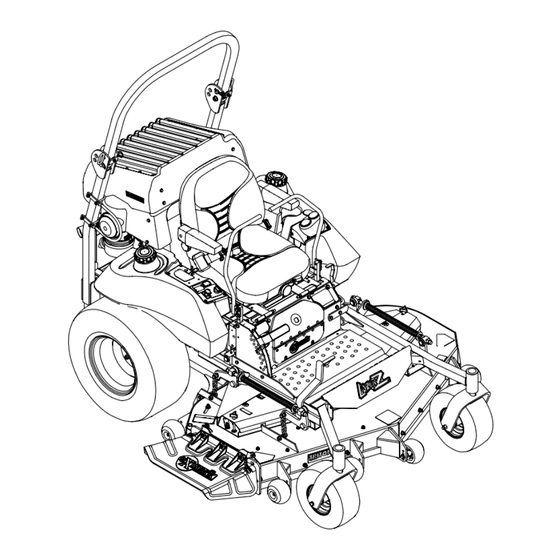
Page 20: Product Overview
Operation Product Overview Operation Note: Determine the left and right sides of the machine from the normal operating position. Controls Motion Control Levers The motion control levers located on each side of the console control the forward and reverse motion of the machine. -
Page 21: Brake Lever
Operation and moving the throttle lever to the rear will decrease The valve has three positions, each position made engine speed. Moving the throttle forward into the in 1/4 turn increments. detent is full throttle. Fuel Flow Valve Handle Position “Off ”... -
Page 22: Pre-Start
Operation Warning Buzzer PTO Engagement Switch Located on right fuel tank. Located behind the seat under the air deflector on the electrical panel. Switch must be pulled out (up) to engage the blades. Switch is pushed in to disengage the blades. The buzzer is a warning signal that the engine is overheating or the oil pressure is low. -
Page 23: Operating Instructions
Operation Important: Do Not use kerosene or gasoline rear part of the seat is secured with the seat instead of diesel fuel. Failure to observe this latch. caution will damage the engine. Do Not overfill fuel tank. Fill the fuel tank to the bottom of the filler neck. -
Page 24: Stopping The Engine
Operation 7. Turn ignition switch to the “ON” position. DANGER Depress the glow plug switch and the glow plug An uncovered discharge opening will allow light will turn on. Hold switch as required by objects to be thrown in an operator’s or chart below. -
Page 25: Driving The Machine
Operation Driving the Machine To turn left or right, pull the motion control lever back toward neutral in the desired turn direction. CAUTION The machine will move faster the farther the Machine can spin very rapidly by positioning one motion control levers are moved from the neutral lever too much ahead of the other. -
Page 26: Adjusting The Anti-Scalp Rollers
Operation The deck can be raised by pulling the deck lever 5. After adjusting the height of cut, adjust the up and/or by pushing down on the foot operated anti-scalp rollers by removing the bolt and spring deck lift assist lever located at the front right disc washer. -
Page 27: Transporting
Operation WARNING Loading a unit on a trailer or truck increases the possibility of backward tip-over. Backward tip-over could cause serious injury or death. • Use extreme caution when operating a unit on a ramp. • Use only a single, full width ramp; Do Not use individual ramps for each side of the unit. -
Page 28: Maintenance
Maintenance Maintenance Note: Determine the left and right sides of the machine from the normal operating position. WARNING WARNING While maintenance or adjustments are being The engine can become very hot. Touching a hot made, someone could start the engine. engine can cause severe burns. -
Page 29: Periodic Maintenance
5. If the oil level is low, wipe off the area around the volts. oil fill cap, remove cap and fill to the “FULL” mark on the dipstick. Exmark 4-Cycle Premium Note: To prevent damage due to freezing, battery Engine Oil is recommended; refer to the Engine should be fully charged before putting away for Owner’s manual for an acceptable alternative. -
Page 30: Recommended Jump Starting Procedure
Maintenance Check the voltage of the battery with a digital DANGER voltmeter. Locate the voltage reading of the battery in Jump starting a weak battery that is cracked, the table and charge the battery for the recommended frozen, has low electrolyte level, or an time interval to bring the charge up to a full charge open/shorted battery cell, can cause an of 12.6 volts or greater. -
Page 31: Check Mower Blades
Maintenance Figure 13 1. Install bushing in blade prior to installing bushing in spindle. Figure 12 1. Positive (+) cable on discharged battery B. Install bushing/blade assembly into spindle. 2. Positive (+) cable on booster battery 3. Negative (–) cable on the booster battery 4. -
Page 32: Check Safety Interlock System
Check Safety Interlock Note: If machine does not pass any of these tests, System do not operate. Contact your authorized EXMARK SERVICE DEALER. Service Interval: Before each use or daily Important: It is essential that operator safety... -
Page 33: Change Engine Oil
Oil level should be to the top of the secure with retaining clips. baffle inside the tank. If not, add oil. Use Exmark Premium Hydro oil. Replace hydraulic reservoir Change Engine Oil cap and tighten until snug. -
Page 34: Check Condition Of Belts
Maintenance 2. Check tire pressure in drive tires. Lubrication Chart 3. Inflate drive tires to 10 psi (69 kPa). Fitting Initial Number of Service 4. Semi-pneumatic caster tires do not need to be Locations Pumps Places Interval inflated. 4. Deck Yearly Note: Do Not add any type of tire liner or foam Drive Belt... -
Page 35: Wheel Hub - Slotted Nut Torque Specification
7. Insert one bearing, one new seal into the wheel. Service Interval: Every 160 hours Note: Seals (Exmark P/N 103-0063) must be 1. Stop engine, wait for all moving parts to stop, and replaced. remove key. Engage parking brake. -
Page 36: Lubricate Motion Control Bronze Bushings
Important: Before reinstalling new filter, fill it with Exmark Premium Hydro oil and apply Change Fuel Filter/Water a thin coat of oil on the surface of the rubber seal. -
Page 37: Check Engine Coolant Level
Maintenance 6. Raise the rear of machine up and support with CAUTION jack stands (or equivalent support) just high Engine coolant is toxic. Swallowing coolant can enough to allow drive wheels to turn freely. cause poisoning. 7. Start engine and move throttle control ahead to •... -
Page 38: Check Spark Arrester (If Equipped)
Maintenance core. As air is purged from the engine block and the coolant level drops, add additional coolant to the radiator. 8. When the radiator is completely full and no additional coolant can be added, continue running and install the radiator cap. Make sure that the cap is completely seated by pressing down firmly while turning until the cap stops. -
Page 39: Mobil Hts Grease (Or Food-Grade Anti-Seize)
Maintenance Adjustments • Fuel tank bulkhead fitting nuts. • Bolts retaining stub shaft to engine flywheel. Note: Disengage PTO, shut off engine, wait for all moving parts to stop, engage parking brake, and Adhesives such as “Loctite RC/609 or RC/680” or remove key before servicing, cleaning, or making any “Fel-Pro Pro-Lock Retaining I or Retaining II”... -
Page 40: Pump Drive Belt Tension
Maintenance Pump Drive Belt Tension the chain bolts in the deck lift arms making sure they don’t move while tightening. Self-tensioning - No adjustment necessary. 9. Loosen the four nuts which secure the front swivels (two per side) until the front chains are Deck Belt Tension loose and front of deck is supported by the 3/4 inch (19 mm) block. -
Page 41: Alternator Belt Tension
Maintenance Belt Guide Adjustment 1. Stop engine, wait for all moving parts to stop, and remove key. Engage parking brake. 2. Remove the belt shield on the right side of mower deck. 3. Note belt guide bolted to deck near the shield support stud and right-hand pulley. - Page 42 Maintenance inch (3.2-4.8 mm). If necessary, adjust the nyloc CAUTION nut accordingly. Raising the mower deck for service or 12. If the correct gap can no longer be achieved maintenance relying solely on mechanical because there is no clearance between the nyloc or hydraulic jacks could be dangerous.
-
Page 43: Electric Clutch Adjustment
Maintenance Electric Clutch Adjustment No adjustment necessary. However when the clutch brake has worn to the point where the clutch no longer engages consistently, the shim can be removed to extend the clutch life. Figure 23 1. Brake mounting bolt 2. -
Page 44: Reverse Indicator Adjustment
Maintenance 5. If adjustment is needed, loosen the nut against the yoke and while applying slight rearward pressure on the motion control lever, turn the head of the adjustment bolt in the appropriate direction until lever is centered (keeping rearward pressure on the lever will keep the pin at the end of the slot and allow the adjustment bolt to move the lever to the appropriate position). - Page 45 Maintenance because of the jumper wire being used. Run CAUTION engine at full throttle and release brake. Raising the mower deck for service or 7. The reverse indicator spring must be correct maintenance relying solely on mechanical before the following adjustments can be made. or hydraulic jacks could be dangerous.
-
Page 46: Motion Control Damper Adjustment
Maintenance Motion Control Damper Adjustment The top damper mounting bolt can be adjusted to obtain a more desired motion control lever resistance. See Figure 29 for mounting options. Figure 30 1. Spring disc washers Figure 29 1. Motion control bracket 2. -
Page 47: Cleaning
Maintenance Cleaning CAUTION Excessive debris around engine and exhaust system area can cause engine, exhaust area, and Clean Engine Cooling hydraulic system to overheat which can create System a fire hazard. Clean all debris from engine and exhaust system Service Interval: Before each use or daily area. -
Page 48: Clean Debris From Machine
Maintenance Battery Disposal Clean Debris From Machine Service Interval: Before each use or daily DANGER 1. Stop engine, wait for all moving parts to stop, and Battery electrolyte contains sulfuric acid, which remove key. Engage parking brake. is poisonous and can cause severe burns. Swallowing electrolyte can be fatal or if it touches 2. -
Page 49: Troubleshooting
Troubleshooting Troubleshooting Important: It is essential that all operator safety mechanisms be connected and in proper operating condition prior to mower use. When a problem occurs, do not overlook the simple causes. For example: starting problems could be caused by an empty fuel tank. The following table lists some of the common causes of trouble. - Page 50 Troubleshooting Problem Possible Cause Corrective Action Engine overheats. 1. Engine load is excessive. 1. Reduce the ground speed. 2. Oil level in the crankcase is low. 2. Add oil to the crankcase. 3. Dirty air filter. 3. Clean or replace the air cleaner element. 4.
- Page 51 Troubleshooting Problem Possible Cause Corrective Action Warning buzzer emits continuous beep. (See 1. Temperature is increasing on coolant 1. Turn unit off and allow engine and engine also Engine overheats). temperature gauge. components to cool. 2. Coolant level is low. 2.
-
Page 52: Schematics
Schematics Schematics Electrical Diagram... - Page 53 Schematics Electrical Schematic...
- Page 54 No Claim of breach of warranty shall be cause for cancellation or rescission of the contract of sale of any Exmark mower. All warranty work must be performed by an authorized Exmark Service Dealer using Exmark approved replacement All implied warranties of merchantability (that the parts.
- Page 55 Notes:...
- Page 56 Notes:...
-
Page 57: Service Record
Service Record Date: Description of Work Done: Service Done By:... - Page 59 Figure 31 This page may be copied for personal use. 1. The maximum slope you can safely operate the machine on is 15 degrees. Use the slope indicator to determine the degree of slope of hills before operating. Do Not operate this machine on a slope greater than 15 degrees. Fold along the appropriate line to match the recommended slope.
- Page 60 SEE EXMARK’S COMPLETE LINE OF ACCESSORIES AND OPTIONS MID-MOUNT RIDING ACCESSORIES AND OPTIONS CUSTOM RIDE SEAT SUSPENSION SYSTEM OPERATOR CONTROLLED DISCHARGE FULL SUSPENSION SEAT ROLL OVER PROTECTION SYSTEM (ROPS) DECK LIFT ASSIST KIT SUN SHADE HITCH KIT TRASH CONTAINER LIGHT KIT...
Need help?
Do you have a question about the LAZER Z D-SERIES and is the answer not in the manual?
Questions and answers