Advertisement
Available languages
Available languages
Quick Links
Installer:
Leave this manual with the appliance.
Consumer: Retain this manual for future reference.
WARNING: If not installed, operated and maintained
in accordance with the manufacturer's instructions,
this product could expose you to substances in fuel
or from fuel combustion which can cause death or
serious illness.
INSTALLATION INSTRUCTIONS
OWNER'S MANUAL
AND
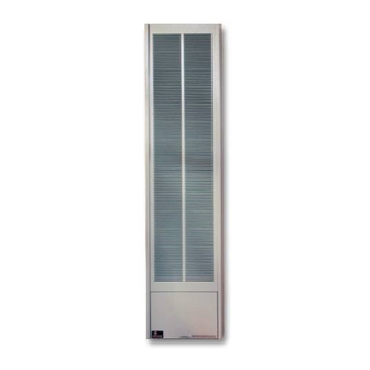
GRAVITY VENTED
DUAL WALL FURNACE
MODEL
GWT-50-2 (SG, RB)
WARNING: If the information in these instructions
are not followed exactly, a fire or explosion may
result causing property damage, personal injury or
loss of life.
— Do not store or use gasoline or other flammable
vapors and liquids in the vicinity of this or any
other appliance.
— WHAT TO DO IF YOU SMELL GAS
•
Do not try to light any appliance.
•
Do not touch any electrical switch; do not use
any phone in your building.
•
Immediately call your gas supplier from a
neighbor's phone. Follow the gas supplier's
instructions.
•
If you cannot reach your gas supplier, call the
fire department.
— Installation and service must be performed by a
qualified installer, service agency or the gas sup-
plier.
Page 1
Advertisement
Chapters

Related Manuals for Empire Heating Systems GWT-50-2 SG


Summary of Contents for Empire Heating Systems GWT-50-2 SG
-
Page 1: Installation Instructions
INSTALLATION INSTRUCTIONS OWNER'S MANUAL GRAVITY VENTED DUAL WALL FURNACE MODEL GWT-50-2 (SG, RB) WARNING: If the information in these instructions are not followed exactly, a fire or explosion may result causing property damage, personal injury or loss of life. — Do not store or use gasoline or other flammable vapors and liquids in the vicinity of this or any other appliance. -
Page 2: Table Of Contents
TABLE OF CONTENTS SECTION PAGE Important Safety Information ..................3 Safety Information for Users of LP Gas ..............4 Introduction ......................5 Specifications ......................5 Recommended Vent Configuration ................6 Gas Supply .......................7 Clearances ......................8 Ventilation and Combustion Air ................8 Location - All Models ....................8 Rough-In Instructions ....................8-9 Finishing Instructions ..................9-10 Thermostat Location (SG Models) ................. -
Page 3: Important Safety Information
IMPORTANT SAFETY INFORMATION THIS IS A HEATING APPLIANCE DO NOT OPERATE THIS APPLIANCE WITHOUT OUTER CASING INSTALLED. • Due to high temperatures the appliance should be • Do not put anything around the furnace that will located out of traffic and away from furniture and obstruct the flow of combustion and ventilation draperies. -
Page 4: Safety Information For Users Of Lp Gas
SAFETY INFORMATION FOR USERS OF LP-GAS Propane (LP-Gas) is a flammable gas which can cause fires point with the members of your household. Someday when and explosions. In its natural state, propane is odorless and there may not be a minute to lose, everyone's safety will depend colorless. You may not know all the following safety precau- on knowing exactly what to do. -
Page 5: Introduction
INTRODUCTION Introduction Such equipment shall be located, or protected, so it is not subject Vented wall furnace is shipped ready to install in a 2" x 4" stud wall, to physical damage by a moving vehicle. with studs 16" (406mm) center to center. Always consult your local Qualified Installing Agency Building Department regarding regulations, codes or ordinances Installation and replacement of gas piping, gas utilization equipment... -
Page 6: Recommended Vent Configuration
RECOMMENDED VENT CONFIGURATION Note: No vent equipment supplied with furnace. 4" Oval (all parts purchase locally) 1. Type B-1 oval pipe 2. Single story type B-1 gas vents require a baseplate and one pair of ceiling plate spacers. 3. Multi-story type B-1 gas vents require a baseplate, one pair of ceiling plate spacers at the first floor ceiling and one pair of fire stop spacers at each successive ceiling level. -
Page 7: Gas Supply
GAS SUPPLY Check all local codes for requirements, especially for the size and type of gas supply line required. Recommended Gas Pipe Diameter Pipe Length Schedule 40 Pipe Tubing, Type L Inside Diameter Outside Diameter Nat. L.P. Nat. L.P. 0-10 feet 1/2”... -
Page 8: Clearances
CLEARANCES In selecting a location for installation, it is necessary to provide NOTE: Minimum distance of 1 1/2" (38mm) must also be maintained adequate accessibility clearances for servicing and proper from top surface of carpeting, tile, etc. installation. Clearances to combustible surfaces are 4" (102mm) from sides, 12"... -
Page 9: Finishing Instructions
62 1/4” (1581 mm) 14 ½” 66 1/8” (368 mm) (1679 mm) WALL OPENING Figure 2 Figure 3 FINISHING INSTRUCTIONS Plastering (Figure 4) Installing Furnace (Figure 5) In new construction use only plain (not perforated) gypsum lath Clear the recess of all debris, and remove any wood plaster-grounds. around furnace and vent pipe so that plaster "Keys"... - Page 10 FINISHING INSTRUCTIONS (continued) IMPORTANT — Avoid securing too tightly and disturbing the inner casing. Do not try to force furnace into a wall opening which is smaller than specified dimension. OUTER CASING (Figure 6) Align 1 3/4" slot on casing bracket with bottom screw hole on inner casing.
-
Page 11: Thermostat Location (Sg Models)
THERMOSTAT LOCATION (SG MODELS) CAUTION — Do not run wire behind flanges of Header Plate or in any location where it might be damaged. Millivolt wall thermostats are specially designed for use on self- generating systems. They should never be used on line or low voltage A.C. -
Page 12: Lighting Instructions
LIGHTING INSTRUCTIONS FOR YOUR SAFETY READ BEFORE LIGHTING WARNING: If you do not follow these instructions exactly, a fire or explosion may result causing property damage, personal injury or loss of life. A. This appliance has a pilot which must be lighted by ment. hand. When lighting the pilot, follow these instructions C. -
Page 13: Vent Safety Shutoff System
VENT SAFETY SHUTOFF SYSTEM This appliance must be properly connected to a venting system. This appliance is equipped with a vent safety shutoff system. Warning: Operation of this wall furnace when not connected to a properly installed and maintained venting system or tampering with the vent safety shutoff system can result in carbon monoxide (CO) poisoning and possible death. -
Page 14: Troubleshooting
TROUBLESHOOTING GENERAL All furnaces have been fire-tested to check for proper and harder. operation. This includes main burner flame, pilot flame, and gas Determine if pilot flame extends past thermopile; if not, adjust pilot flame or clean pilot burner. control operation. If the furnace fails to function on initial installation, it is advisable to re-check the following: Replace thermopile if millivolt reading is less than 300 millivolts Inlet gas pressure. -
Page 15: Parts List
PARTS LIST ATTENTION: When ordering parts, it is very important that part number and description of part coincide. INDEX PART NO. DESCRIPTION INDEX PART NO. DESCRIPTION WFA-115 HEADER GASKET R1054 THERMOPILE GWT-175 HEADER ASSEMBLY GWT-096 BURNER BRACKET ASSEMBLY (INCLUDES NO. 1, GASKET) (USA) R5245 GAS VALVE - NAT 15756... -
Page 16: Parts View
PARTS VIEW Page 16 12426-15-0811... -
Page 17: Remote Bulb Control Installation Instructions
REMOTE BULB CONTROL INSTALLATION INSTRUCTIONS MODELS GWT-25 RB, GWT-35 RB, GWT-50 RB Note: The remote bulb control may be located on the left or TO VENT SAFETY right side of the outer casing. Remove remote bulb control from the shipping carton. Remove outer casing assembly from shipping carton. -
Page 18: Optional Blower Installation Instructions
OPTIONAL BLOWER INSTALLATION INSTRUCTIONS GWTB-2 FOR MODELS GWT-25 (SG, RB), GWT-35 (SG, RB), GWT-50 (SG, RB) Installing Blower Using Three-Prong Plug 1. Install furnace according to Installation Instructions and Owner's Installing Blower With Hard Wiring Manual. 1. When facing the wall opening, install 120V electrical outlet junction box 2. - Page 19 GWTB-2 WIRING DIAGRAM 13” (330 mm) 4 7/16” (112.6 mm) Figure 3 Fan Control The automatic fan control is located on the bottom of the blower assembly. The fan control is a nonadjustable, automatic type. The fan control will require between 3 and 7 minutes of main burner operation before the fan control "closes"...
- Page 20 Empire Comfort Systems Inc. EMPIRE EMPIRE 918 Freeburg Ave. Belleville, IL 62220 If you have a general question about our products, please e-mail us at info@empirecomfort.com. If you have a service or repair question, please contact your dealer. Comfort Systems www.empirecomfort.com Page 20 12426-15-0811...
- Page 21 InstructIons Pour l’InstallatIon Manuel du ProPrIétaIre FournaIse à aIr chaud Par graVIté Pour Mur MItoyen Modèles gWt-50-2(sg, rB) aVertIsseMent: assurez vous de bien suivre les instructions données dans cette notice pour réduire au minimum le risque d’incendie ou d’explosion ou pour éviter tout dommage matériel, toute blessure ou la mort.
- Page 22 taBle des MatIères sectIon Page Information Importante de Sécurité ..................3 Information de Sécurité pour les Utilisateurs de Propane ............4 Introduction ..........................5 Spécifications..........................5 Recommended Vent Configuration ..................6 Alimentation en Gaz .......................7 Espaces Libres ........................8 Air de Ventilation et de Combustion ..................8 Emplacement - Pour Tous les Modèles ..................8 Instructions Sommaires ......................
-
Page 23: Information Importante De Sécurité
InForMatIon IMPortante de sécurIté cecI est un aPPareIl de chauFFage NE PAS FAIRE FoNCTIoNNER CET APPAREIL SANS qUE LA PARoI ExTéRIEURE SoIT INSTALLéE. • • A cause des hautes températures, cet appareil doit être situé Ne rien mettre autour de la fournaise qui pourrait obstruer le débit de combustion et la ventilation d’air. -
Page 24: Information De Sécurité Pour Les Utilisateurs De Propane
InForMatIon de sécurIté Pour les utIlIsateurs de ProPane Le propane est un gaz inflammable qui peut causer des feux et des réexaminez les, point par point avec les membres de votre famille. explosions. dans son état naturel, le propane est inodore et sans Un jour, lorsqu’il n’y aura pas une minute à... -
Page 25: Introduction
IntroductIon Introduction avis: Pendant le premier allumage de cette unité, la peinture cuira Lorsque la fournaise murale à air chaud est expédiée, elle est prête et de la fumée se produira. Pour prévenir les détecteurs de fumée à être installer entre les montants du mur 2" x 4" (51mm x 102mm) de se déclencher, bien ventiler l’appartement dans lequel l’unité... - Page 26 conFIguratIon recoMMandée Pour l’éVacuatIon note: Aucun matériel d’évacuation est fourni avec l’appareil. MINIMUM 10' (3.05m) oU Ovale de 4" (102mm) (toutes les pièces sont achetées localement) CAPUCHoN D’éVENT MoINS 1. Tuyau ovale de type B-1 ENREGISTRé Les tuyaux d’évacuation de type B-1 pour un étage exigent une plaque de base et une paire d’entretoises pour le plafond.
-
Page 27: Alimentation En Gaz
alIMentatIon en gaZ Vérifier tous les codes locaux pour répondre aux exigences, CONNEXION D’UNE LIGNE DE GAZ FLEXIBLE spécialement pour la grandeur et le genre de ligne requise pour ALIMENTATION DE GAZ ½ MAMELON l’alimentation de gaz. TUBE FLEXIBLE ½ Le Diamètre recommandé... -
Page 28: Espaces Libres
esPaces lIBres note: Une distance minimum de 1 1/2" (38mm) doit aussi être 1. En choisissant un emplacement, il est nécessaire de fournir l’espace libre adéquat pour l’accès à l’installation et à maintenue pour le dessus des tapis, tuiles, etc. l’entretien. -
Page 29: Instructions Pour La Finition
ÉVENT B AVEC UN ADAPTATEUR BW INSTALLATION ÉLECTRIQUE PERMANENTE FACULTATIVE D’UNE PRISE DE COURANT 115VOLT POUR LA SOUFFLERIE FACULTATIVE JOINT D’ÉTANCHÉITÉ POUR L’ENSEMBLE COLLECTEUR BAS DU REBORD CLOUÉ DU PLAQUE COLLECTRICE COLLECTEUR 62 ½” (1581 mm) 14 ½” PLAQUE COLLECTRICE (368 mm) 66 1/8”... - Page 30 InstructIons Pour la FInItIon (suite) IMPortant Éviter de fixer la fournaise trop serrée et de pertuber la paroi in- LoRSqUE LA SoUFFLERIE EST INSTALLéE, UTILISER LES 2 VIS térieure. N’essayer pas de forcer la fournaise dans une ouverture ExTéRIEURES. UTILISER LA VIS DU MILIEU LoRSqUE murale qui serait plus petite que les dimensions mentionnées.
-
Page 31: Emplacement Du Thermostat (Modèles Sg)
eMPlaceMent du therMostat (Modèles sg) attentIon — Ne placer pas des fils électriques derrière les Brancher les fils du thermostat à la valve de gaz comme il est rebords de la plaque collectrice ou quelque part où ils seraient représenté à la Figure 7. endommagés. -
Page 32: Instructions D'allumage
InstructIons d'alluMage Pour Votre sécurIté lIre aVant d’alluMer aVertIsseMent: si vous ne suivez pas exactement ces instructions, un feu ou une explosion peut se produire causant des dommages à la propriété, des blessures corporelles ou la mort. cet appareil a une veilleuse qui doit être allumée manuel- du fournisseur de gaz. -
Page 33: Le Système De Fermeture De Sûreté De L'évent
le systèMe de FerMeture de sûreté de l’éVent Le Système de Fermeture de Sûreté de l’Évent. L’éVENT DE SûRETé Cet appareil doit être branché correctement à un système d’évacuation. Cet appareil est muni d’un système de fermeture de sûreté de l’évent. aVertIsseMent: le fonctionnement de cette fournaise murale lorsqu’elle n’est pas branchée à... -
Page 34: Détection Des Défectuosités
détectIon des déFectuosItés général: Toutes les fournaises ont reçu un test d’allumage en aucune Façon, la Veilleuse ne s’allume Pas pour vérifier le bon fonctionnement. Ceci inclus la flamme du 1. Vérifier le bouton de contrôle de gaz, il doit être dans la brûleur principal, la flamme de la veilleuse et le fonctionnement position “Veilleuse”. -
Page 35: Listes Des Pièces
lIste des PIèces attentIon: Lorsque vous commandez les pièces, il est très important que le numéro de la pièce et la description coïncident. Numéro Numéro Description Numéro Numéro Description d’index de la pièce d’index de la pièce WFA-115 Joint d’étanchéité du collecteur GWT-096 Ensemble du support du brûleur GWT-175... -
Page 36: Vue Des Pièces
Vue des PIèces Page 16 12426-15-0811... -
Page 37: Instructions Pour L'installation De La Commande Lumineuse À Distance
InstructIons Pour l’InstallatIon de la coMMande luMIneuse à dIstance Modèles gWt-25-rB, gWt-35-rB, gWt-50-rB À L’ÉVENT DE SÛRETÉ Note: Au choix du propriétaire, la commande lumineuse à dis- tance peut être placée sur le côté gauche ou droit de la paroi extérieure. -
Page 38: Instructions Pour L'installation De La Soufflerie Facultative
InstructIons Pour l’InstallatIon de la souFFlerIe FacultatIVe Installation de la Soufflerie en Utilisant une Fiche à Trois Broches extérieure. Visser complètement les vis du châssis de la soufflerie au Installer la fournaise selon les Instructions pour l’Installation et Manuel mur. Ce sont les vis de l’étape 3. du Propriétaire. - Page 39 GWTB-2 DIAGRAMME DE L’INSTALLATIoN éLECTRIqUE 1 ½” 13” (38 mm) (330.2 mm) 1 ½” (38mm) (2) TROU DE MONTAGE DE LA SOUFFLERIE (FACULTATIF) TROU D’ACCES 13mm DIA. 4 7/16 (112.6 mm) CHÂSSIS DE LA SOUFFLERIE 2 1/16” (52 mm) AVANT DE LA SOUFFLERIE Figure 3 commande du Ventilateur...
-
Page 40: Notes De Service
notes de serVIce Empire Comfort Systems Inc. EMPIRE EMPIRE 918 Freeburg Ave. Belleville, IL 62220 Pour toute question générale concernant nos produits, veuillez nous envoyer un courriel à info@empirecomfort.com. Pour toute question Comfort Systems d’entretien ou de réparation, veuillez contacter votre revendeur. www.empirecomfort.com Page 20 12426-15-0811...
Need help?
Do you have a question about the GWT-50-2 SG and is the answer not in the manual?
Questions and answers