Table of Contents
Advertisement
Quick Links
Advertisement
Table of Contents

Related Manuals for Asus P5MT-C


Summary of Contents for Asus P5MT-C
- Page 1 P5MT-C...
- Page 2 Product warranty or service will not be extended if: (1) the product is repaired, modified or altered, unless such repair, modification of alteration is authorized in writing by ASUS; or (2) the serial number of the product is defaced or missing.
-
Page 3: Table Of Contents
Contents Notices ....................vii Safety information ................viii About this guide .................. ix Typography ..................x P5MT-C specifications summary ............xi Chapter 1: Product introduction Welcome! ................1-1 Package contents ..............1-1 Special features ..............1-2 1.3.1 Product highlights ........... 1-2 1.3.2... - Page 4 Managing and updating your BIOS ........4-1 4.1.1 Creating a bootable floppy disk ......4-1 4.1.2 AFUDOS utility ............4-2 4.1.3 ASUS CrashFree BIOS 2 utility ........ 4-5 4.1.4 ASUS Update utility ..........4-7 BIOS setup program ............4-10 4.2.1 BIOS menu screen ..........4-11 4.2.2...
- Page 5 Contents 4.4.3 Remote Access Configuration ....... 4-20 4.4.4 CPU Configuration ..........4-21 4.4.5 Chipset ..............4-22 4.4.6 Onboard Devices Configuration ......4-24 4.4.7 PCI PnP ..............4-25 Power Menu ................ 4-26 4.5.1 ACPI APIC Support ..........4-26 4.5.2 APM Configuration ..........4-27 4.5.3 Hardware Monitor ..........
- Page 6 5.3.5 Checking the drives for data consistency ..... 5-31 5.3.6 Deleting a RAID configuration ....... 5-34 5.3.7 Selecting the boot drive from a RAID set ..... 5-35 5.3.8 Enabling the WriteCache ........5-36 Global Array Manager ............5-36 Chapter 6: Driver installation RAID driver installation ............
-
Page 7: Notices
Notices Federal Communications Commission Statement This device complies with Part 15 of the FCC Rules. Operation is subject to the following two conditions: • This device may not cause harmful interference, and • This device must accept any interference received including interference that may cause undesired operation. -
Page 8: Safety Information
Safety information Electrical safety • To prevent electrical shock hazard, disconnect the power cable from the electrical outlet before relocating the system. • When adding or removing devices to or from the system, ensure that the power cables for the devices are unplugged before the signal cables are connected. -
Page 9: About This Guide
Refer to the following sources for additional information and for product and software updates. ASUS websites The ASUS website provides updated information on ASUS hardware and software products. Refer to the ASUS contact information. Optional documentation Your product package may include optional documentation, such as warranty flyers, that may have been added by your dealer. -
Page 10: Typography
Conventions used in this guide To make sure that you perform certain tasks properly, take note of the following symbols used throughout this manual. DANGER/WARNING: Information to prevent injury to yourself when trying to complete a task. CAUTION: Information to prevent damage to the components when trying to complete a task. -
Page 11: P5Mt-C Specifications Summary
P5MT-C specifications summary LGA775 socket for Intel Pentium 4/processor ® ® Compatible with Intel PCG 05B/05A and 04B/04A and ® the latest Intel Smithfield dual-core processor ® Supports Intel Enhanced Memory 64 Technology (EM64T) ® Supports Enhanced Intel SpeedStep Technology (EIST) ®... - Page 12 ATX 12 V 2.0 compliant Requirement ATX form factor: 12 in x 9.8 in (30.5 cm x 24.9 cm) Form Factor Device drivers Support CD ASUS Live Update utility contents ASUS Server Web-based Management (ASWM) Anti-virus software *Specifications are subject to change without notice.
- Page 13 This chapter describes the motherboard features and the new technologies it supports. Product introduction...
- Page 14 Chapter summary Welcome! ................1-1 Package contents ..............1-1 Special features ..............1-2 ASUS P5MT-C...
-
Page 15: Welcome
® The motherboard delivers a host of new features and latest technologies, making it another standout in the long line of ASUS quality motherboards! Before you start installing the motherboard, and hardware devices on it, check the items in your package with the list below. -
Page 16: Special Features
Special features 1.3.1 Product highlights Latest processor technology The motherboard comes with a 775-pin surface mount Land Grid Array (LGA) socket designed for the Intel Pentium 4 processor in the 775-land ® ® package. The motherboard supports the Intel Pentium 4 processor with ®... - Page 17 The system fan rotations per minute (RPM) is monitored for timely failure detection. The ASIC monitors the voltage levels to ensure stable supply of current for critical components. See page 4-29 for details. ASUS P5MT-C...
-
Page 18: Innovative Asus Features
ROM chip. See page 4-5 for details. ASUS Smart Fan technology The ASUS Smart Fan technology smartly adjusts the fan speeds according to the system loading to ensure quiet, cool, and efficient operation. - Page 19 This chapter lists the hardware setup procedures that you have to perform when installing system components. It includes description of the jumpers and connectors on the motherboard. Hardware information...
- Page 20 Chapter summary Before you proceed .............. 2-1 Motherboard overview ............2-2 Central Processing Unit (CPU) ..........2-6 System memory ..............2-13 Expansion slots ..............2-15 Jumpers ................2-18 Connectors ................. 2-23 ASUS P5MT-C...
-
Page 21: Before You Proceed
This is a reminder that you should shut down the system and unplug the power cable before removing or plugging in any motherboard component. The illustration below shows the location of the onboard LED. SB_PWR1 Standby Powered Power P5MT-C Onboard LED ASUS P5MT-C... -
Page 22: Motherboard Overview
Motherboard overview Before you install the motherboard, study the configuration of your chassis to ensure that the motherboard fits into it. To optimize the motherboard features, we highly recommend that you install it in an SSI EEB 3.5 compliant chassis. Make sure to unplug the power cord before installing or removing the motherboard. -
Page 23: Motherboard Layout
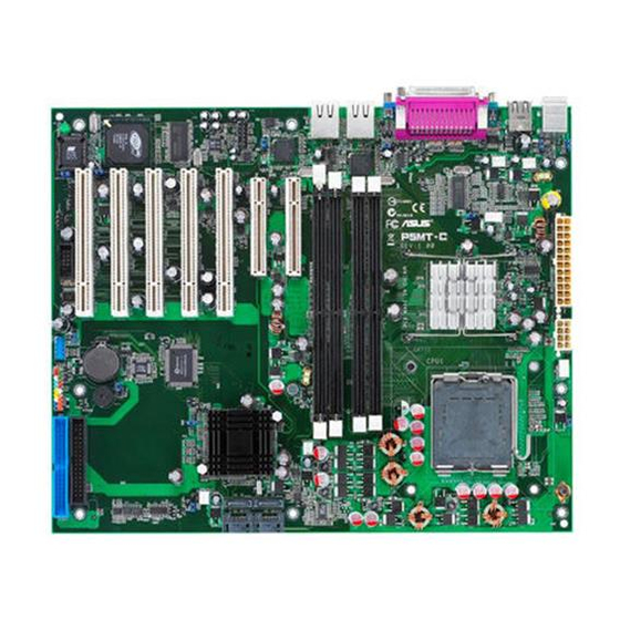
ALC850 FRNT_FAN2 PCI2 Super CHASSIS1 RAID_SEL1 USB56 PCI3 USBPW56 RAGE XL USB78 CLRTC1 PCI4 USBPW78 Controller CR2032 3V BUZZ1 Lithium Cell VGA_EN1 CMOS Power PCI5 FLOPPY1 8Mbit Flash USBPW34 TRPWR1 PRI_IDE1 BIOS PANEL1 BPSMB1 USB34 COM2 RECOVERY1 HDLED1 ASUS P5MT-C... -
Page 24: Layout Contents
2.2.4 Layout contents Slots/Sockets Page CPU socket DDR2 DIMM slots 2-13 PCI/PCI Express slots 2-17 Jumpers Page Clear RTC RAM (CLRTC1) 2-18 CPU fan pin selection (3-pin FM_CPU1, FM_CPU2) 2-19 USB device wake-up (3-pin USBPW12, USBPW34, USBPW56, USBPW78) 2-19 Keyboard power (3-pin KBPWR1) 2-20 VGA controller setting (3-pin VGA_EN1) 2-20... - Page 25 2-27 Ambient thermal sensor (2-pin TRPWR1) 2-27 CPU and system fan connectors (3-pin CPU_FAN1/2, 2-28 REAR_FAN1/2, FRNT_FAN1/2) Backplane SMBus connector (6-1 pin BPSMB1) 2-28 SSI power connectors (24-pin ATXPWR1, 8-pin ATX12V2) 2-29 System panel connector (20-pin PANEL1) 2-30 ASUS P5MT-C...
-
Page 26: Central Processing Unit (Cpu)
Contact your retailer immediately if the PnP cap is missing, or if you see any damage to the PnP cap/socket contacts/motherboard components. ASUS shoulders the repair cost only if the damage is shipment/ transit-related. •... - Page 27 (B). Load plate Position the CPU over the socket, making sure that the gold triangle is on the bottom-left corner of the socket. The socket alignment Alignment key key should fit into the CPU notch. Gold triangle mark ASUS P5MT-C...
- Page 28 The CPU fits in only one correct orientation. DO NOT force the CPU into the socket to prevent bending the connectors on the socket and damaging the CPU! Close the load plate (A), then push the load lever (B) until it snaps into the retention tab.
-
Page 29: Installing The Cpu Heatsink And Fan
CPU fan connector. Motherboard hole Narrow end Fastener of the groove Make sure to orient each fastener with the narrow end of the groove pointing outward. (The photo shows the groove shaded for emphasis.) ASUS P5MT-C... - Page 30 Push down two fasteners at a time in a diagonal sequence to secure the heatsink and fan assembly in place. Connect the CPU fan cable to the connector on the motherboard labeled CPU_FAN1/CPU_FAN2. 2-10 Chapter 2: Hardware information...
-
Page 31: Uninstalling The Cpu Heatsink And Fan
To uninstall the CPU heatsink and fan: Disconnect the CPU fan cable from the connector on the motherboard. Rotate each fastener counterclockwise. Pull up two fasteners at a time in a diagonal sequence to disengage the heatsink and fan assembly from the motherboard. ASUS P5MT-C 2-11... - Page 32 Rotate each fastener clockwise to ensure correct orientation when reinstalling. Narrow end of the groove The narrow end of the groove should point outward after resetting. (The photo shows the groove shaded for emphasis.) Refer to the documentation in the boxed or stand-alone CPU fan package for detailed information on CPU fan installation.
-
Page 33: System Memory
128 Pins 112 Pins DIMM_A1 DIMM_A2 DIMM_B1 DIMM_B2 P5MT-C 240-pin DDR2 DIMM Sockets 2.4.2 Memory configurations You may install 256 MB, 512 MB, 1 GB, and 2 GB unbuffered ECC or non-ECC DDR2-533/667 DIMMs into the DIMM sockets. • Always install DIMMs with the same CAS latency. For optimum compatibility, we recommend that you obtain memory modules from the same vendor. -
Page 34: Installing A Dimm
2.4.3 Installing a DIMM Unplug the power supply before adding or removing DIMMs or other system components. Failure to do so can cause severe damage to both the motherboard and the components. To install a DIMM: DDR2 DIMM notch Unlock a DIMM socket by pressing the retaining clips outward. -
Page 35: Expansion Slots
“Share IRQ” or that the cards do not need IRQ assignments. Otherwise, conflicts will arise between the two PCI groups, making the system unstable and the card inoperable. Refer to the table on the next page for details. ASUS P5MT-C 2-15... -
Page 36: Interrupt Assignments
2.5.3 Interrupt assignments Standard interrupt assignments Priority Standard Function System Timer Keyboard Controller — Re-direct to IRQ#9 Communications Port (COM2)* Communications Port (COM1)* IRQ holder for PCI steering* Floppy Disk Controller Printer Port (LPT1)* System CMOS/Real Time Clock IRQ holder for PCI steering* IRQ holder for PCI steering* IRQ holder for PCI steering* PS/2 Compatible Mouse Port*... -
Page 37: Pci Express X8 Slot
PCI slots The PCI slots support cards such as a LAN card, SCSI card, USB card, and other cards that comply with PCI 2.3 specifications. The figure shows a LAN card installed on a 32-bit PCI slot. ASUS P5MT-C 2-17... -
Page 38: Jumpers
Except when clearing the RTC RAM, never remove the cap on CLRTC jumper default position. Removing the cap will cause system boot failure! CLRTC1 Normal Clear CMOS (Default) P5MT-C Clear RTC RAM 2-18 Chapter 2: Hardware information... - Page 39 FM_CPU2 3-pin fan 4-pin fan (Default) P5MT-C FM CPU Setting USB device wake-up (3-pin USBPW12, USBPW34, USBPW56, USBPW78) Set these jumpers to +5V to wake up the computer from S1 sleep mode (CPU stopped, DRAM refreshed, system running in low power mode) using the connected USB devices.
- Page 40 +5VSB lead, and a corresponding setting in the BIOS. KBPWR1 +5VSB (Default) P5MT-C Keyboard Power Setting VGA controller setting (3-pin VGA_EN1) These jumpers allow you to enable or disable the onboard ATI ® RAGE-XL PCI VGA controller. Set to pins 1-2 to activate the VGA feature.
- Page 41 ® BCM5753 Gigabit LAN1 or LAN2 controller. Set to pins 1-2 to activate the Gigabit LAN controller. LAN_EN1 Enable Disable (Default) P5MT-C LAN_EN1 Setting LAN_EN2 Enable Disable (Default) P5MT-C LAN_EN2 Setting RAID controller selection (3-pin RAID_SEL1) This jumper allows you to select the RAID configuration utility to use when you create disk arrays.
- Page 42 Insert the floppy disk then turn on the system to update the BIOS. Shut down the system. Set the jumper back to pins 1-2. Turn on the system. RECOVERY1 Normal BIOS recovery (Default) P5MT-C BIOS Recovery Setting 2-22 Chapter 2: Hardware information...
-
Page 43: Connectors
LAN port LED indications. LAN port LED indications ACT/LINK SPEED ACT/LINK LED SPEED LED Status Description Status Description No link 10 Mbps connection GREEN Linked 100 Mbps connection BLINKING Data activity GREEN 1 Gbps connection LAN port ASUS P5MT-C 2-23... -
Page 44: Internal Connectors
PIN 1 NOTE: Orient the red markings on the floppy ribbon cable to PIN 1. P5MT-C Floppy Disk Drive Connector ICH7R Primary IDE connector (40-1 pin PRI_IDE1) This connector is for an Ultra DMA 100/66/33 signal cable. The Ultra DMA 100/66/33 signal cable has three connectors: a blue connector... -
Page 45: Serial Ata Hard Disk Drive Connection
RSATA_TXP2 RSATA_TXP0 RSATA_TXN2 RSATA_TXN0 RSATA_RXN2 RSATA_RXN0 RSATA_RXP2 RSATA_RXP0 P5MT-C SATA Connectors Important notes on Serial ATA • You must install Windows 2000 Service Pack 4 or Windows 2003 ® ® before using Serial ATA hard disk drives. The Serial ATA RAID feature (RAID 0/RAID 1) is available only if you are using Windows ®... -
Page 46: Hard Disk Activity Led Connector (4-Pin Hdled)
SCSI connectors or the SATA connectors cause this LED to light up. HDLED1 P5MT-C SCSI/SATA Card Activity LED Connector USB connectors (10-1 pin USB34, USB56, USB78) These connectors are for USB 2.0 ports. Connect the USB module cable to this connector, then install the module to a slot opening at the back of the system chassis. -
Page 47: Serial Port Connector (10-1 Pin Com)
The serial port module is purchased separately. COM2 PIN 1 P5MT-C Serial Port2 (COM2) Connector Ambient thermal sensor (2-pin TRPWR1) If you want additional thermal monitoring, connect the thermal sensor cable with thermistor (of 1ºK or at 25ºC, B=3435) to this connector. -
Page 48: Backplane Smbus Connector (6-1 Pin Bpsmb)
+12V FRNT_FAN1 FRNT_FAN1 FRNT_FAN2 FRNT_FAN2 P5MT-C Fan Connectors Backplane SMBus connector (6-1 pin BPSMB1) This connector allows you to connect SMBus (System Management Bus) devices. Devices communicate with an SMBus host and/or other SMBus devices using the SMBus interface. BPSMB1... -
Page 49: Ssi Power Connectors (24-Pin Atxpwr1, 8-Pin Atx12V)
• You must install a PSU with a higher power rating if you intend to install additional devices. ATXPWR1 ATX12V2 24-pin Power Connector P5MT-C ATX Power Connectors ASUS P5MT-C 2-29... -
Page 50: System Panel Connector (20-Pin Panel)
Reset button (Blue 2-pin RESET) This 2-pin connector is for the chassis-mounted reset button for system reboot without turning off the system power. PANEL1 P5MT-C System Panel Connector The system panel connector is color-coded for easy connection. 2-30 Chapter 2: Hardware information... -
Page 51: Chapter 3: Powering Up
This chapter describes the power up sequence, the vocal POST messages, and ways of shutting down the system. Powering up... - Page 52 Chapter summary Starting up for the first time ..........3-1 Powering off the computer ........... 3-2 ASUS P5MT-C...
-
Page 53: Starting Up For The First Time
Two continuous beeps followed by Floppy controller failure two short beeps Two continuous beeps followed by Hardware component failure four short beeps At power on, hold down the <Del> key to enter the BIOS Setup. Follow the instructions in Chapter 4. ASUS P5MT-C... -
Page 54: Powering Off The Computer
Powering off the computer 3.2.1 Using the OS shut down function If you are using Windows Server 2000: ® Click the Start button then click Shut Down... Make sure that the Shut Down option button is selected, then click the OK button to shut down the computer. The power supply should turn off after Windows shuts down. -
Page 55: Chapter 4: Bios Setup
This chapter tells how to change the system settings through the BIOS Setup menus. Detailed descriptions of the BIOS parameters are also provided. BIOS setup... - Page 56 Chapter summary Managing and updating your BIOS ........4-1 BIOS setup program ............4-10 Main menu ................4-13 Advanced menu ..............4-18 Power menu ................ 4-26 Boot menu ................4-30 Exit menu ................4-34 ASUS P5MT-C...
-
Page 57: Managing And Updating Your Bios
The following utilities allow you to manage and update the motherboard Basic Input/Output System (BIOS) setup. ASUS AFUDOS (Updates the BIOS in DOS mode using a bootable floppy disk.) ASUS CrashFree BIOS 2 (Updates the BIOS using a bootable floppy disk or the motherboard support CD when the BIOS file fails or gets... -
Page 58: Afudos Utility
Press <Enter>. The utility copies the current BIOS file to the floppy disk. A:\>afudos /oOLDBIOS1.rom AMI Firmware Update Utility - Version 1.19(ASUS V2.07(03.11.24BB)) Copyright (C) 2002 American Megatrends, Inc. All rights reserved. Reading flash ..done Write to file..ok A:\>... -
Page 59: Updating The Bios File
Updating the BIOS file To update the BIOS file using the AFUDOS utility: Visit the ASUS website (www.asus.com) and download the latest BIOS file for the motherboard. Save the BIOS file to a bootable floppy disk. Write the BIOS filename on a piece of paper. You need to type the exact BIOS filename at the DOS prompt. - Page 60 The utility returns to the DOS prompt after the BIOS update process is completed. Reboot the system from the hard disk drive. A:\>afudos /iP5MT-C.ROM /pbnc AMI Firmware Update Utility - Version 1.19(ASUS V2.07(03.11.24BB)) Copyright (C) 2002 American Megatrends, Inc. All rights reserved. WARNING!! Do not turn off power during flash BIOS Reading file ..
-
Page 61: Asus Crashfree Bios 2 Utility
4.1.3 ASUS CrashFree BIOS 2 utility The ASUS CrashFree BIOS 2 is an auto recovery tool that allows you to restore the BIOS file when it fails or gets corrupted during the updating process. You can update a corrupted BIOS file using the motherboard support CD or the floppy disk that contains the updated BIOS file. -
Page 62: Recovering The Bios From The Support Cd
Restart the system after the utility completes the updating process. The recovered BIOS may not be the latest BIOS version for this motherboard. Visit the ASUS website (www.asus.com) to download the latest BIOS file. Chapter 4: BIOS setup... -
Page 63: Asus Update Utility
4.1.4 ASUS Update utility The ASUS Update is a utility that allows you to manage, save, and update the motherboard BIOS in Windows environment. The ASUS Update utility ® allows you to: • Save the current BIOS file • Download the latest BIOS file from the Internet •... -
Page 64: Updating The Bios Through The Internet
To update the BIOS through the Internet: Launch the ASUS Update utility from the Windows desktop by clicking ® Start > Programs > ASUS > ASUSUpdate > ASUSUpdate. The ASUS Update main window appears. Select Update BIOS from Select the ASUS FTP site... -
Page 65: Updating The Bios Through A Bios File
To update the BIOS through a BIOS file: Launch the ASUS Update utility from the Windows desktop by ® clicking Start > Programs > ASUS > ASUSUpdate > ASUSUpdate. The ASUS Update main window appears. Select Update BIOS from a file option from the drop-down menu, then click Next. -
Page 66: Bios Setup Program
The BIOS setup screens shown in this section are for reference purposes only, and may not exactly match what you see on your screen. • Visit the ASUS website (www.asus.com) to download the latest BIOS file for this motherboard. 4-10 Chapter 4: BIOS setup... -
Page 67: Bios Menu Screen
At the bottom right corner of a menu screen are the navigation keys for that particular menu. Use the navigation keys to select items in the menu and change the settings. Some of the navigation keys differ from one screen to another. ASUS P5MT-C 4-11... -
Page 68: Menu Items
[Wed, 06/01/2005] Legacy Diskette A [1.44M, 3.5 in] bar displays the specific items for Primary IDE Master :[ST320410A] Primary IDE Slave :[ASUS CD-S520/A] that menu. For example, selecting Third IDE Master :[Not Detected] Third IDE Slave :[Not Detected] Fourth IDE Master :[Not Detected] Main shows the Main menu items. -
Page 69: Main Menu
field. Legacy Diskette A [1.44M, 3.5 in.] Primary IDE Master : [ST320410A] Use [+] or [-] to Primary IDE Slave : [ASUS CD-S520/A] configure the System Third IDE Master : [Not Detected] time. Third IDE Slave : [Not Detected]... -
Page 70: Primary/Third/Fourth Ide Master/Slave
4.3.4 Primary, Third, and Fourth IDE Master/Slave While entering Setup, the BIOS automatically detects the presence of IDE devices. There is a separate sub-menu for each IDE device. Select a device item then press <Enter> to display the IDE device information. Primary IDE Master Select the type of device connected to... -
Page 71: Ide Configuration
Allows selection of the IDE operation mode depending on the operating system (OS) that you installed. Set to Enhanced Mode if you are using native OS, such as Windows 2000. Configuration options: [Disabled] ® [Compatible Mode] [Enhanced Mode] ASUS P5MT-C 4-15... - Page 72 If the Onboard IDE Operate Mode is set to [Compatible], you can only use the SATA2, SATA4, and P-ATA connectors. Enhanced Mode Support On [S-ATA] The default setting SATA allows you to use native OS on Serial ATA and Parallel ATA ports. We recommend that you do not change the default setting for better OS compatibility.
-
Page 73: System Information
: Genuine Intel(R) CPU 3.20 GHz Speed : 3200 MHz Count System Memory Size : 512 MB AMI BIOS Displays the auto-detected BIOS information. Processor Displays the auto-detected CPU specification. System Memory Displays the auto-detected system memory. ASUS P5MT-C 4-17... -
Page 74: Advanced Menu
Advanced menu The Advanced menu items allow you to change the settings for the CPU and other system devices. Take caution when changing the settings of the Advanced menu items. Incorrect field values can cause the system to malfunction. USB settings. USB Configuration MPS Configuration Remote Access Configuration... -
Page 75: Mps Configuration
This menu allows you to configure the Multi-Processor table. Select an item then press <Enter> to display the configuration options. MPS Configuration Select MPS Revision. MPS Revision [1.4] MPS Revision [1.4] Allows you to choose the MPS revision. Configuration options: [1.1] [1.4] ASUS P5MT-C 4-19... -
Page 76: Remote Access Configuration
4.4.3 Remote Access Configuration The items in this menu allow you to configure the Remote Access features. Select an item then press <Enter> to display the configuration options. Configure Remote Access type and parameters Select Remote Access type. Remote Access [Disabled] Remote Access [Disabled] Enables or disables the remote access feature. -
Page 77: Cpu Configuration
Hardware Prefetcher [Enabled] Allows you to enable or disable the hardware prefetcher feature. Configuration options: [Disabled] [Enabled] Adjacent Cache Line Prefetch [Enabled] Allows you to enable or disable the adjacent cache line prefetch feature. Configuration options: [Disabled] [Enabled] ASUS P5MT-C 4-21... -
Page 78: Chipset
CPU Internal Thermal Control [Auto] Disables or sets the CPU internal thermal control. Configuration options: [Auto] [Disabled] The following item appears only when you installed an Intel Pentium ® ® processor that supports Hyper Threading Technology. Hyper Threading Technology [Enabled] Allows you to enable or disable the processor Hyper Threading Technology. - Page 79 Allows you to disable or set the PCI Express Graphics port VC1 map. Configuration options: [Disabled] [TC1] ~ [TC7] PEG Force x1 [Disabled] Configuration options: [Disabled] [Enabled] Memory Remap Feature [Enabled] Allows you to enable or disable the memory remap feature. Configuration options: [Disabled] [Enabled] ASUS P5MT-C 4-23...
-
Page 80: Onboard Devices Configuration
4.4.6 Onboard Devices Configuration Configure Win627EHF Super IO Chipset Enable or disable the Azalia controller. Serial Port1 Address [3F8/IRQ4] Serial Port2 Address [2F8/IRQ3] Serial Port2 Mode [Normal] Parallel Port Address [378] Parallel Port Mode [ECP] ECP Mode DMA Channel [DMA3] Parallel Port IRQ [IRQ7] Serial Port1 Address [3F8/IRQ4]... -
Page 81: Pci Pnp
PCI VGA card even if requested. Configuration options: [Yes] [No] Palette Snooping [Disabled] When set to [Enabled], the palette snooping feature informs the PCI devices that an ISA graphics device is installed in the system so that the latter can function correctly. Configuration options: [Disabled] [Enabled] ASUS P5MT-C 4-25... -
Page 82: Power Menu
IRQ-xx assigned to [PCI Device] When set to [PCI Device], the specific IRQ is free for use of PCI/PnP devices. When set to [Reserved], the IRQ is reserved for legacy ISA devices. Configuration options: [PCI Device] [Reserved] Power menu The Power menu items allow you to change the settings for the ACPI and Advanced Power Management (APM). -
Page 83: Apm Configuration
When set to [Enabled], this parameter allows you to turn on the system through a PCI LAN or modem card. This feature requires an ATX power supply that provides at least 1A on the +5VSB lead. Configuration options: [Disabled] [Enabled] ASUS P5MT-C 4-27... -
Page 84: Hardware Monitor
OnboardLan Wakeup [Disabled] Allows you to enable or disable the onboard LAN to turn on the system. Configuration options: [Disabled] [Enabled] Keyboard Wakeup Password This item appears only when the Power On By PS/2 Keyboard is set to Enabled. Select this item to set or change the keyboard wakeup password. The Keyboard Wakeup Password item that appears below shows the default Not Installed. - Page 85 (RPM). If the fan is not connected to the motherboard, the field shows N/A. Smart Fan Control [Enabled] Allows you to enable or disable the ASUS Smart Fan feature that smartly adjusts the fan speeds for more efficient system operation. Configuration options: [Disabled] [Enabled] When Smart Fan Control item is set to [Enabled], the CPU Target Temperature and MB Target Temperature items appear.
-
Page 86: Boot Menu
Boot menu The Boot menu items allow you to change the system boot options. Select an item then press <Enter> to display the sub-menu. Boot Settings Specifies the Boot Device Boot Priority Boot Device Priority sequence. Boot Settings Configuration Security Select Screen Select Item Enter Go to Sub-screen... -
Page 87: Boot Settings Configuration
This allows you to enable or disable the full screen logo display feature. Configuration options: [Disabled] [Enabled] Set this item to [Enabled] to use the ASUS MyLogo2™ feature. AddOn ROM Display Mode [ForceBIOS] Sets the display mode for the option ROM. -
Page 88: Security
Hit ʻDELʼ Message Display [Enabled] When set to Enabled, the system displays the message “Press DEL to run Setup” during POST. Configuration options: [Disabled] [Enabled] Interrupt 19 Capture [Disabled] When set to [Enabled], this function allows the option ROMs to trap Interrupt 19. -
Page 89: Change User Password
To set a User Password: Select the Change User Password item and press <Enter>. On the password box that appears, type a password composed of at least six letters and/or numbers, then press <Enter>. Confirm the password when prompted. ASUS P5MT-C 4-33... -
Page 90: Clear User Password
The message “Password Installed” appears after you set your password successfully. To change the user password, follow the same steps as in setting a user password. Clear User Password Select this item to clear the user password. Password Check [Setup] When set to [Setup], BIOS checks for user password when accessing the Setup utility. -
Page 91: Discard Changes
Setup menus. When you select this option or if you press <F5>, a confirmation window appears. Select OK to load default values. Select Exit & Save Changes or make other changes before saving the values to the non-volatile RAM. ASUS P5MT-C 4-35... - Page 92 4-36 Chapter 4: BIOS setup...
-
Page 93: Raid Support
This chapter provides information on RAID configurations for this motherboard. RAID support... - Page 94 Chapter summary RAID configurations .............. 5-1 Intel Matrix Storage Manager option ROM utility ....5-3 LSI Logic Embedded SATA RAID Setup Utility ....5-14 Global Array Manager ............5-36 ASUS P5MT-C...
-
Page 95: Raid Definitions
If you want to boot the system from a hard disk drive included in a created RAID set, copy first the RAID driver from the support CD to a floppy disk before you install an operating system to the selected hard disk drive. Refer to section “6.1 RAID driver installation” for details. ASUS P5MT-C... -
Page 96: Installing Serial Ata Hard Disks
5.1.2 Installing Serial ATA hard disks The motherboard supports Serial ATA hard disk drives. For optimal performance, install identical drives of the same model and capacity when creating a disk array. To install the SATA hard disks for a RAID configuration: Install the SATA hard disks into the drive bays. -
Page 97: Intel Matrix Storage Manager Option Rom Utility
The navigation keys at the bottom of the screen allow you to move through the menus and select the menu options. The RAID BIOS setup screens shown in this section are for reference only and may not exactly match the items on your screen. ASUS P5MT-C... -
Page 98: Creating A Raid 0 Set (Striped)
5.2.1 Creating a RAID 0 set (striped) To create a RAID 0 set: From the utility main menu, select 1. Create RAID Volume, then press <Enter>. This screen appears. Intel(R) Matrix Storage Manager Option ROM v5.0.0.1032 ICH7R wRAID5 Copyright(C) 2003-05 Intel Corporation. All Rights Reserved. CREATE ARRAY MENU Name: Volume0... - Page 99 WARNING: ALL DATA ON SELECTED DISKS WILL BE LOST. Are you sure you want to create this volume? (Y/N): Press <Y> to create the RAID volume and return to the main menu, or <N> to go back to the Create Volume menu. ASUS P5MT-C...
-
Page 100: Creating A Raid 1 Set (Mirrored)
5.2.2 Creating a RAID 1 set (mirrored) To create a RAID 1 set: From the utility main menu, select 1. Create RAID Volume, then press <Enter>. This screen appears. Intel(R) Matrix Storage Manager Option ROM v5.0.0.1032 ICH7R wRAID5 Copyright(C) 2003-05 Intel Corporation. All Rights Reserved. CREATE ARRAY MENU Name: Volume1... -
Page 101: Creating A Raid 10 Set (Raid 0+1)
Key in the RAID volume capacity that you want then press <Enter> when the Capacity item is highlighted. The default value indicates the maximum allowed capacity. ASUS P5MT-C... -
Page 102: Creating A Raid 5 Set (Parity)
Press <Enter> when the Create Volume item is highlighted. This warning message appears. WARNING: ALL DATA ON SELECTED DISKS WILL BE LOST. Are you sure you want to create this volume? (Y/N): Press <Y> to create the RAID volume and return to the main menu or <N>... - Page 103 WARNING: ALL DATA ON SELECTED DISKS WILL BE LOST. Are you sure you want to create this volume? (Y/N): Press <Y> to create the RAID volume and return to the main menu or <N> to go back to the Create Volume menu. ASUS P5MT-C...
-
Page 104: Deleting A Raid Set
5.2.5 Deleting a RAID set Take caution when deleting a RAID set. You will lose all data on the hard disk drives when you delete a RAID set. To delete a RAID set: From the utility main menu, select 2. Delete RAID Volume, then press <Enter>... -
Page 105: Resetting Disks To Non-Raid
From the utility main menu, select 4. Exit, then press <Enter>. This window appears. CONFIRM EXIT Are you sure you want to exit? (Y/N): Press <Y> to exit or press <N> to return to the utility main menu. ASUS P5MT-C 5-11... -
Page 106: Rebuilding The Raid
5.2.8 Rebuilding the RAID This option is only for the RAID 1, RAID 5 and RAID 10 sets. Rebuilding the RAID with other non-RAID disk If any of the SATA hard disk drives included in the RAID array failed, the system displays the status of the RAID volume as “Degraded”... -
Page 107: Setting The Boot Array In The Bios Setup Utility
Use up/down arrow keys to select the boot priority and press <Enter>. Refer to “4.6.1 Boot Device Priority” for details. From the Exit menu, select Exit & Save Changes, then press <Enter>. When the confirmation window appears, select OK, then press <Enter>. ASUS P5MT-C 5-13... -
Page 108: Lsi Logic Embedded Sata Raid Setup Utility
LSI Logic Embedded SATA RAID Setup Utility The LSI Logic Embedded SATA RAID Setup Utility allows you to create RAID 0, RAID 1, and RAID 10 set(s) from SATA hard disk drives connected to the SATA connectors supported by the motherboard Southbridge chip. The LSI Logic Embedded SATA RAID automatically configures a RAID 1 (Mirrored) set when the SATA is configured as RAID in the BIOS and you installed two hard disk drives without a RAID configuration. -
Page 109: Creating A Raid Set
In Easy Configuration, the logical drive parameters are set automatically including the size and stripe size (RAID 1 only). In New Configuration, you manually set the logical drive parameters and assign the set size and stripe size (RAID 1 only). ASUS P5MT-C 5-15... - Page 110 Using Easy Configuration To create a RAID set using the Easy Configuration option: From the utility main menu, highlight Configure, then press <Enter>. Use the arrow keys to select Easy Configuration, then press <Enter>. The ARRAY SELECTION MENU displays the available drives connected to the SATA ports.
- Page 111 Select all the drives required for the RAID set, then press <Enter>. The configurable array appears on screen. Press <F10>, select the configurable array, then press <SpaceBar>. The logical drive information appears including a Logical Drive menu that allows you to change the logical drive parameters. ASUS P5MT-C 5-17...
- Page 112 Select RAID from the Logical Drive menu, then press <Enter>. Select the RAID level from the menu, then press <Enter>. You need at least two identical hard disk drives when creating a RAID 1 set. When creating a RAID 1 or a RAID 10 set, select Stripe Size from the Logical Drive menu, then press <Enter>.
- Page 113 10. When finished setting the selected logical drive configuration, select Accept from the menu, then press <Enter>. 11. Follow steps 5 to 10 to configure additional logical drives. 12. When prompted, save the configuration, then press <Esc> to return to the Management Menu. ASUS P5MT-C 5-19...
- Page 114 Using New Configuration When a RAID set is already existing, using the New Configuration command erases the existing RAID configuration data. If you do not want to delete the existing RAID set, use the View/Add Configuration command to view or create another RAID configuration. To create a RAID set using the New Configuration option: From the utility main menu, highlight Configure, then press <Enter>.
-
Page 115: Adding Or Viewing A Raid Configuration
RAID set, then press <SpaceBar>. When selected, the drive indicator changes from READY to ONLIN A[X]-[Y], where X is the array number, and Y is the drive number. The information of the selected hard disk drive displays at the bottom of the screen. ASUS P5MT-C 5-21... - Page 116 Select all the drives required for the RAID set, then press <Enter>. The configurable array appears on screen. Press <F10>, select the configurable array, then press <SpaceBar>. The logical drive information appears including a Logical Drive menu that allows you to change the logical drive parameters. 5-22 Chapter 5: Driver installation...
- Page 117 Select Size from the Logical Drive menu, then press <Enter>. Key in the desired logical drive size, then press <Enter>. Follow steps 8 to 12 of the Creating a RAID set: Using Easy Configuration section to add the new RAID configuration. ASUS P5MT-C 5-23...
-
Page 118: Initializing The Logical Drives
5.3.3 Initializing the logical drives After creating the RAID set(s), you must initialize the logical drives. You may initialize the logical drives of a RAID set(s) using the Initialize or Objects command in the Management Menu. Using the Initialize command To initialize the logical drive using the Initialize command: From the Management Menu, highlight Initialize, then press <Enter>. - Page 119 Initialize? dialog box, then press <Enter>. You may also press <F10> to initialize the drive without confirmation. Initializing a logical drive(s) erases all data on the drive. A progress bar appears on screen. If desired, press <Esc> to abort initialization. ASUS P5MT-C 5-25...
- Page 120 When initialization is completed, press <Esc>. Using the Objects command To initialize the logical drives using the Objects command: From the Management Menu, highlight Objects, then press <Enter>. 5-26 Chapter 5: Driver installation...
- Page 121 Select Logical Drive from the Objects sub-menu, then press <Enter>. Select the logical drive to initialize from the Logical Drives sub-menu, then press <Enter>. Select Initialize from the pop-up menu, then press <Enter> to start initialization. ASUS P5MT-C 5-27...
- Page 122 When prompted, press the <SpaceBar> to select Yes from the Initialize? dialog box, then press <Enter>. You may also press <F10> to initialize the drive without confirmation. A progress bar appears on screen. If desired, press <Esc> to abort initialization. When initialization is completed, press <Esc>.
-
Page 123: Rebuilding Failed Drives
To rebuild a failed hard disk drive using the Rebuild command: From the Management Menu, highlight Rebuild, then press <Enter>. The PHYSICAL DRIVES SELECTION MENU displays the available drives connected to the SATA ports. Select the drive you want to rebuild, then press <SpaceBar>. ASUS P5MT-C 5-29... - Page 124 After selecting the drive to rebuild, press <F10>. The indicator for the selected drive now shows RBLD. When prompted, press <Y> to to rebuild the drive. When rebuild is complete, press any key to continue. Using the Objects command To rebuild a failed hard disk drive using the Objects command: From the Management Menu, select Objects, then select Physical Drive from the menu.
-
Page 125: Checking The Drives For Data Consistency
From the Management Menu, select Check Consistency, then press <Enter>. The screen displays the available RAID set(s) and prompts you to select the logical drive to check. Use the arrow keys to select the logical drive from the Logical Drive selection, then press <Enter>. ASUS P5MT-C 5-31... - Page 126 When prompted, press the <SpaceBar> to select Yes from the Consistency Check dialog box, then press <Enter>. You may also press <F10> to check the drive consistency. A progress bar appears on screen. While checking the disk consistency, press <Esc> to display the following options.
- Page 127 Use the arrow keys to select the logical drive you want to check, then press <Enter>. Select Check Consistency from the pop-up menu, then press <Enter>. When prompted, press <Y> to to check the drive. When checking is complete, press any key to continue. ASUS P5MT-C 5-33...
-
Page 128: Deleting A Raid Configuration
5.3.6 Deleting a RAID configuration To delete a RAID configuration: From the Management Menu, select Configure > Clear Configuration, then press <Enter>. When prompted, press the <SpaceBar> to select Yes from the Clear Configuration? dialog box, then press <Enter>. The utility clears the current array. Press any key to continue. -
Page 129: Selecting The Boot Drive From A Raid Set
From the Management Menu, select Configure > Select Boot Drive, then press <Enter>. When prompted, press the <SpaceBar> to select the bootable logical drive from the list, then press <Enter>. The logical drive is selected as boot drive. Press any key to continue. ASUS P5MT-C 5-35... -
Page 130: Enabling The Writecache
5.3.8 Enabling the WriteCache You may enable the RAID controllerʼs WriteCache option to improve the data transmission performance. When you enable WriteCache, you may lose data when a power interruption occurs while transmitting or exchanging data among the drives. To enable WriteCache: From the Management Menu, select Objects >... -
Page 131: Chapter 6: Driver Installation
This chapter provides information on RAID, LAN and VGA driver installation for this motherboard. Driver installation... - Page 132 Chapter summary RAID driver installation ............6-1 LAN driver installation ............6-11 VGA driver installation ............6-13 Management applications and utilities installation ....6-15 ASUS P5MT-C...
-
Page 133: Raid Driver Installation
Follow screen instructions to create the driver disk. For systems with Red Hat Enterprise versions that are not listed in the ® Makedisk menu, explore the support CD and copy the RAID driver disk from the following path: \Drivers\ICH7R\LSI\Linux. ASUS P5MT-C... - Page 134 Windows 2000/2003 Server ® To create a RAID driver disk in Windows 2000/2003 Server environment: ® Restart the system from the hard disk drive, then place the system/ motherboard support CD in the optical drive. Browse the contents of the support CD to locate the driver disk utility.
-
Page 135: Installing The Raid Controller Driver
2000/2003 Setup starts. ® Press <F6> when the message “Press F6 if you need to install a third party SCSI or RAID driver...” appears at the bottom of the screen. When prompted, press <S> to specify an additional device. ASUS P5MT-C... - Page 136 Insert the RAID driver disk you created earlier to the floppy disk drive, then press <Enter>. Select the RAID controller driver from the list, then press <Enter>. For LSI Logic Embedded SATA RAID driver, select LSI Logic Embedded SATA RAID. Chapter 6: Driver installation...
- Page 137 New Hardware Found window. Click Cancel. Right-click the My Computer icon on the Windows desktop , then ® select Properties from the menu. Click the Hardware tab, then click the Device Manager button to display the list of devices installed in the system. ASUS P5MT-C...
- Page 138 Right-click the RAID controller item, then select Properties. Click the Driver tab, then click the Update Driver button. The Upgrade Device Driver Wizard window appears. Click Next. Insert the RAID driver disk you created earlier to the floppy disk drive. Select the option “Search for a suitable driver for my device (recommended)”, then click Next.
- Page 139 Intel(R) 82801GR/GH SATA RAID Controller item should appear. Right-click the RAID controller driver item, then select Properties from the menu. Click the Driver tab, then click the Driver Details button to display the RAID controller drivers. Click OK when finished. ASUS P5MT-C...
- Page 140 Red Hat Enterprise ver. 3.0 ® To install the RAID controller driver when installing Red Hat Enterprise ver. ® 3.0 OS: Boot the system from the Red Hat Installation CD. ® At the boot:, type linux dd , then press <Enter>. Chapter 6: Driver installation...
- Page 141 Select Yes using the <Tab> key when asked if you have the driver disk. Press <Enter> Select fd0 using the <Tab> key when asked to select the driver disk source. Press <Tab> to move the cursor to OK, then press <Enter>. ASUS P5MT-C...
- Page 142 When prompted, insert the Red Hat Enterprise ver. 3.0 RAID driver ® disk to the floppy disk drive, select OK, then press <Enter>. The drivers for the RAID controller are installed to the system. When asked if you will load additional RAID controller drivers, select No, then press <Enter>.
-
Page 143: Lan Driver Installation
If Autorun is NOT enabled in your computer, browse the contents of the support CD to locate the file ASSETUP.EXE from the BIN folder. Double-click the ASSETUP.EXE to run the CD. Click the Broadcom 5753 Driver option to begin installation. ASUS P5MT-C 6-11... -
Page 144: Red Hat ® Enterprise Ver. 3.0
Click Next when the InstallShield Wizard window appears. Follow screen instructions to continue installation. 6.2.2 Red Hat Enterprise ver. 3.0 ® Follow these instructions when installing the Broadcom Gigabit LAN ® controller base driver for the Red Hat Enterprise ver. 3.0 operating ®... -
Page 145: Vga Driver Installation
® Hardware Found window. Click Cancel to close this window. Click the item ATI Rage XL Display Driver from the Drivers menu. The ATI Windows 2000 Driver window appears. Click Next. Follow screen instructions to complete installation. ASUS P5MT-C 6-13... -
Page 146: Windows ® 2003 Server
6.3.2 Windows 2003 Server ® The Windows 2003 Server operating system automatically recognizes the ® RAGE XL VGA driver during system installation. There is no need to ® install an additional driver(s) to support the onboard VGA. Verifying the VGA driver installation To verify if the ATI RAGE XL VGA drivers are properly installed in a ®... -
Page 147: Running The Support Cd
The contents of the support CD are subject to change at any time without notice. Visit the ASUS website (www.asus.com) for updates. 6.4.1 Running the support CD Place the support CD to the optical drive. -
Page 148: Management Software Menu
Click on an item to install. 6.4.5 Contact information Click the Contact tab to display the ASUS contact information. You can also find this information on the inside front cover of this user guide. 6-16 Chapter 6: Driver installation... -
Page 149: Appendix: Reference Information
This appendix includes additional information that you may refer to when configuring the motherboard. Reference information... - Page 150 Appendix summary Intel EM64T ................. A-1 ® Enhanced Intel SpeedStep Technology (EIST) ....A-1 ® Intel Hyper-Threading Technology ........A-3 ® Block diagrams ..............A-4 ASUS P5MT-C...
-
Page 151: Intel ® Em64T
32-bit operating systems. • The motherboard comes with a BIOS file that supports EM64T. You can download the latest BIOS file from the ASUS website (www.asus. com/support/download/) if you need to update the BIOS file. See Chapter 4 for details. -
Page 152: Using The Eist
A.2.2 Using the EIST To use the EIST feature: Turn on the computer, then enter the BIOS Setup. Go to the Advanced Menu, highlight CPU Configuration, then press <Enter>. Set the Intel(R) SpeedStep Technology item to [Automatic], then press <Enter>. See page 4-22 for details. Press <F10>... -
Page 153: Intel ® Hyper-Threading Technology
Power up the system and enter the BIOS Setup. Under the Advanced Menu, make sure that the item Hyper-Threading Technology is set to Enabled. See page 4-22 for details. The BIOS item appears only if you installed a CPU that supports Hyper-Threading Techonology. Restart the computer. ASUS P5MT-C... -
Page 154: Block Diagram
Block diagrams Appendix: CPU features...
Need help?
Do you have a question about the P5MT-C and is the answer not in the manual?
Questions and answers