Asus Motherboard P5LD2 Manual
Asus motherboard p5ld2
Hide thumbs
Also See for Motherboard P5LD2:
- Troubleshooting manual (144 pages) ,
- User manual (142 pages)
Table of Contents
Advertisement
Advertisement
Table of Contents

Related Manuals for Asus Motherboard P5LD2


Summary of Contents for Asus Motherboard P5LD2
- Page 1 P5LD2...
- Page 2 Product warranty or service will not be extended if: (1) the product is repaired, modified or altered, unless such repair, modification of alteration is authorized in writing by ASUS; or (2) the serial number of the product is defaced or missing.
-
Page 3: Table Of Contents
Welcome! ... 1-1 Package contents ... 1-1 Special features ... 1-2 1.3.1 Product highlights ... 1-2 1.3.2 ASUS AI Lifestyle features ... 1-5 1.3.3 Innovative ASUS features ... 1-6 Chapter 2: Hardware information Before you proceed ... 2-1 Motherboard overview ... 2-2 2.2.1... - Page 4 Managing and updating your BIOS ... 4-1 4.1.1 Creating a bootable floppy disk ... 4-1 4.1.2 AFUDOS utility ... 4-2 4.1.3 ASUS CrashFree BIOS 2 utility ... 4-5 4.1.4 ASUS EZ Flash utility ... 4-7 4.1.5 ASUS Update utility ... 4-8 BIOS setup program ... 4-11 4.2.2...
- Page 5 Manuals menu ... 5-5 5.2.5 Contact information ... 5-6 5.2.6 Other information ... 5-6 Software information ... 5-9 5.3.1 ASUS MyLogo™ ... 5-9 5.3.2 AI NET2 ... 5-11 5.3.3 Audio configurations ... 5-12 RAID configurations ... 5-17 5.4.1 Installing Serial ATA hard disks ... 5-18 5.4.2...
-
Page 6: Canadian Department Of Communications Statement
Notices Federal Communications Commission Statement This device complies with Part 15 of the FCC Rules. Operation is subject to the following two conditions: • This device may not cause harmful interference, and • This device must accept any interference received including interference that may cause undesired operation. -
Page 7: Electrical Safety
Safety information Electrical safety • To prevent electrical shock hazard, disconnect the power cable from the electrical outlet before relocating the system. • When adding or removing devices to or from the system, ensure that the power cables for the devices are unplugged before the signal cables are connected. -
Page 8: About This Guide
Refer to the following sources for additional information and for product and software updates. ASUS websites The ASUS website provides updated information on ASUS hardware and software products. Refer to the ASUS contact information. Optional documentation Your product package may include optional documentation, such as warranty flyers, that may have been added by your dealer. -
Page 9: Conventions Used In This Guide
Conventions used in this guide To make sure that you perform certain tasks properly, take note of the following symbols used throughout this manual. DANGER/WARNING: Information to prevent injury to yourself when trying to complete a task. CAUTION: Information to prevent damage to the components when trying to complete a task. -
Page 10: P5Ld2 Specifications Summary
88E8053 PCI Express™ Gigabit LAN controller ® Supports Marvell Virtual Cable Tester technology ® Supports POST Network-diagnostic program ASUS AI Overclocking ASUS NOS™ (Non-delay Overclocking System) ASUS C.P.R. (CPU Parameter Recall) Fixed PCI Express/PCI/SATA frequencies (continued on the next page) 4/Intel Core™ 2 ®... - Page 11 150 MHz at 1 MHz increment • Stepless Frequency Selection (SFS) from 100 MHz up to 450 MHz at 1 MHz increment ASUS Q-Fan ASUS CrashFree BIOS 2 ASUS MyLogo 4 Mb FLASH ROM, AMI BIOS, PnP, DMI2.0, SM BIOS 2.3, WfM2.0...
- Page 12 P5LD2 specifications summary Support CD contents *Specifications are subject to change without notice. Device drivers ASUS PC Probe II ASUS Update ASUS AI Booster Microsoft DirectX ® Anti-Virus Utility Adobe Acrobat Reader ASUS Screensaver...
-
Page 13: Chapter 1: Product Introduction
This chapter describes the motherboard features and the new technologies it supports. Product introduction... -
Page 14: Chapter Summary
Chapter summary Welcome! ... 1-1 Package contents ... 1-1 Special features ... 1-2 ASUS P5LD2... -
Page 15: Welcome
Thank you for buying an ASUS The motherboard delivers a host of new features and latest technologies, making it another standout in the long line of ASUS quality motherboards! Before you start installing the motherboard, and hardware devices on it, check the items in your package with the list below. -
Page 16: Special Features
Special features 1.3.1 Product highlights Latest processor technology The motherboard comes with a 775-pin surface mount Land Grid Array (LGA) socket designed for the Intel package. The motherboard supports the Intel 1066/800/533 MHz Front Side Bus (FSB). The motherboard also supports the Intel Hyper-Threading Technology and is fully compatible with Intel ®... -
Page 17: Serial Ata Technology
The motherboard supports the S/PDIF technology through the coaxial and optical S/PDIF Out ports on the rear panel. The S/PDIF technology turns your computer into a high-end entertainment system with digital connectivity to powerful audio and speaker systems. See pages 2-23 for details. ASUS P5LD2... - Page 18 USB 2.0 technology The motherboard implements the Universal Serial Bus (USB) 2.0 specification, dramatically increasing the connection speed from the 12 Mbps bandwidth on USB 1.1 to a fast 480 Mbps on USB 2.0. USB 2.0 is backward compatible with USB 1.1. See pages 2-23 and 2-28 for details. Gigabit LAN solution The motherboard comes with a PCI Express Gigabit LAN controller to provide a total solution for your networking needs.
-
Page 19: Asus Ai Lifestyle Features
WiFi-TV Card (optional) The ASUS WiFi-TV card complies with the IEEE 802.11a/b/g standard for wireless LAN and allows data transmission of up to 54 Mbps. ASUS provides full software application support and a user-friendly wizard to help you set up your wireless local area network effortlessly. You can share photos, videos, and MP3 files with other wireless devices without tangling cables and wires. -
Page 20: Asus Mylogo
ROM chip. See page 4-5 for details. ASUS Q-Fan technology The ASUS Q-Fan technology smartly adjusts the fan speeds according to the system loading to ensure quiet, cool, and efficient operation. See page 4-36 for details. - Page 21 This chapter lists the hardware setup procedures that you have to perform when installing system components. It includes description of the jumpers and connectors on the motherboard. Hardware information...
- Page 22 Chapter summary Before you proceed ... 2-1 Motherboard overview ... 2-2 Central Processing Unit (CPU) ... 2-6 System memory ... 2-13 Expansion slots ... 2-17 Jumpers ... 2-20 Connectors ... 2-22 ASUS P5LD2...
-
Page 23: Before You Proceed
This is a reminder that you should shut down the system and unplug the power cable before removing or plugging in any motherboard component. The illustration below shows the location of the onboard LED. ® P5LD2 Onboard LED ASUS P5LD2 SB_PWR Standby Powered Power... -
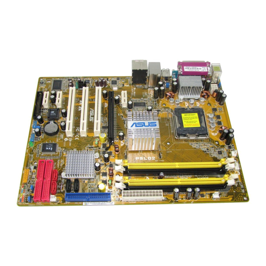
Page 24: Motherboard Overview
Motherboard overview Before you install the motherboard, study the configuration of your chassis to ensure that the motherboard fits into it. Make sure to unplug the power cord before installing or removing the motherboard. Failure to do so can cause you physical injury and damage motherboard components. -
Page 25: Layout/Dimensions
Bass Top:Line In Center:Line Out Below:Mic In PCIEX1_1 Marvell 88E8053 ALC882 AAFP PCIEX1_2 LPC I/O Winbond W83627EHF PCIEX1_3 FLOPPY ASUS P5LD2 23cm (9in) CHA_FAN2 LGA775 Intel 945P PCIEX16 PCI1 ® PCI2 PCI3 Intel FWH CR2032 3V Lithium Cell 4Mbit CMOS Power... -
Page 26: Layout Contents
2.2.4 Layout contents Slots DDR2 DIMM slots PCI slots PCI Express slot Jumpers Clear RTC RAM (3-pin CLRTC) USB Device wake-up (3-pin USBPW12, USBPW34, Keyboard power (3-pin KBPWR) Rear panel connectors PS/2 mouse port (green) Parallel port LAN (RJ-45) port Side Speaker Out port (black) Center/Subwoofer port (yellow orange) Line In port (light blue) - Page 27 System panel connector (20-1 pin PANEL) System power LED (Green 3-pin PLED) Hard disk drive activity LED (Red 2-pin IDE_LED) System warning speaker (Orange 4-pin SPEAKER) ATX power button/soft-off button (Yellow 2-pin PWRSW) Reset button (Blue 2-pin RESET) ASUS P5LD2 Page 2-24 2-24 2-25 2-25...
-
Page 28: Central Processing Unit (Cpu)
Contact your retailer immediately if the PnP cap is missing, or if you see any damage to the PnP cap/socket contacts/motherboard components. ASUS will shoulder the cost of repair only if the damage is shipment/ transit-related. •... - Page 29 The socket alignment key should fit into the CPU notch. ASUS P5LD2 Load plate Alignment key Gold triangle mark PnP cap This side of the socket box should face you.
- Page 30 The CPU fits in only one correct orientation. DO NOT force the CPU into the socket to prevent bending the connectors on the socket and damaging the CPU! Close the load plate (A), then push the load lever (B) until it snaps into the retention tab.
-
Page 31: Installing The Cpu Heatsink And Fan
CPU fan cable is closest to the CPU fan connector. Make sure to orient each fastener with the narrow end of the groove pointing outward. (The photo shows the groove shaded for emphasis.) ASUS P5LD2 Pentium ® ® Pentium 4 LGA775 heatsink and fan assembly comes in ®... - Page 32 Push down two fasteners at a time in a diagonal sequence to secure the heatsink and fan assembly in place. Connect the CPU fan cable to the connector on the motherboard labeled CPU_FAN. ® P5LD2 CPU fan connector Do not forget to connect the CPU fan connector! Hardware monitoring errors can occur if you fail to plug this connector.
-
Page 33: Uninstalling The Cpu Heatsink And Fan
Rotate each fastener counterclockwise. Pull up two fasteners at a time in a diagonal sequence to disengage the heatsink and fan assembly from the motherboard. Carefully remove the heatsink and fan assembly from the motherboard. ASUS P5LD2 2-11... - Page 34 Rotate each fastener clockwise to ensure correct orientation when reinstalling. The narrow end of the groove should point outward after resetting. (The photo shows the groove shaded for emphasis.) Refer to the documentation in the boxed or stand-alone CPU fan package for detailed information on CPU fan installation.
-
Page 35: System Memory
4 GB system memory when you installed four 1 GB DDR2 memory modules. • This motherboard does not support memory modules made up of 128 Mb chips or double sided x16 memory modules. ASUS P5LD2 Sockets DIMM_A1 and DIMM_A 2-13... - Page 36 Qualified Vendors Lists (QVL) DDR2-533 Size Vendor 512 MB SAMSUNG M378T6553BG0-CD5 256 MB SAMSUNG M378T3253FG0-CD5 512 MB SAMSUNG M378T6453FG0-CD5 512 MB Infineon HYS64T64000GU-3.7-A 256 MB Infineon HYS64T32000HU-3.7-A 1024 MB Infineon HYS64T128020HU-3.7-A 512 MB Infineon HYS64T64000HU-3.7-A 512 MB CORSAIR CM2X512-4200 512 MB MICRON MT16HTF6464AG-53EB2 1024 MB MICRON MT16HTF12864AY-53EA1 4...
- Page 37 Supports one pair of modules inserted into either the yellow slots or the black slots as one pair of Dual-channel memory configuration. Supports two pairs of modules inserted into the yellow and black slots as two pairs of Dual-channel memory configuration. Visit the ASUS website for the latest DDR2-677/533/400 MHz QVL. ASUS P5LD2 Brand Side(s)
-
Page 38: Installing A Dimm
2.4.3 Installing a DIMM Unplug the power supply before adding or removing DIMMs or other system components. Failure to do so can cause severe damage to both the motherboard and the components. To install a DIMM: Unlock a DIMM socket by pressing the retaining clips outward. -
Page 39: Expansion Slots
“Share IRQ” or that the cards do not need IRQ assignments. Otherwise, conflicts will arise between the two PCI groups, making the system unstable and the card inoperable. Refer to the table on the next page for details. ASUS P5LD2 2-17... -
Page 40: Standard Interrupt Assignments
2.5.3 Interrupt assignments Standard interrupt assignments Priority — * These IRQs are usually available for ISA or PCI devices. IRQ assignments for this motherboard PCI slot 1 PCI slot 2 PCI slot 3 PCI E x16 slot PCI E x1 slot 1 PCI E x1 slot 2 PCI E x1 slot 3 Onboard USB controller 0... -
Page 41: Pci Slots
PCI Express x1 slot This motherboard supports PCI Express x1 network cards, SCSI cards and other cards that comply with the PCI Express specifications. The following figure shows a network card installed on the PCI Express x1 slot. ASUS P5LD2 2-19... -
Page 42: Clear Rtc Ram
Jumpers Clear RTC RAM (CLRTC) This jumper allows you to clear the Real Time Clock (RTC) RAM in CMOS. You can clear the CMOS memory of date, time, and system setup parameters by erasing the CMOS RTC RAM data. The onboard button cell battery powers the RAM data in CMOS, which include system setup information such as system passwords. -
Page 43: Usb Device Wake-Up
(the default is the Space Bar). This feature requires an ATX power supply that can supply at least 1A on the +5VSB lead, and a corresponding setting in the BIOS. ® P5LD2 Keyboard power setting ASUS P5LD2 USBPW34 USBPW12 +5VSB (Default) -
Page 44: Connectors
Connectors 2.7.1 Rear panel connectors PS/2 mouse port (green). This port is for a PS/2 mouse. Parallel port. This 25-pin port connects a parallel printer, a scanner, or other devices. LAN (RJ-45) port. This port allows Gigabit connection to a Local Area Network (LAN) through a network hub. - Page 45 S/PDIF cable. 14. Coaxial S/PDIF Out port. This port connects an external audio output device via a coaxial S/PDIF cable. 15. PS/2 keyboard port (purple). This port is for a PS/2 keyboard. ASUS P5LD2 4-channel 6-channel Line In...
-
Page 46: Internal Connectors
2.7.2 Internal connectors Floppy disk drive connector (34-1 pin FLOPPY) This connector is for the provided floppy disk drive (FDD) signal cable. Insert one end of the cable to this connector, then connect the other end to the signal connector at the back of the floppy disk drive. Pin 5 on the connector is removed to prevent incorrect cable connection when using a FDD cable with a covered Pin 5. - Page 47 0, RAID 1, RAID 5, or RAID 10 configuration with the Intel Storage Technology through the onboard Intel Refer to Chapter 5 for details on how to set up Serial ATA RAID configurations. ASUS P5LD2 PRI_IDE NOTE: Orient the red markings (usually zigzag) on the IDE ribbon cable to PIN 1.
- Page 48 • These connectors are set to Standard IDE mode by default. In Standard IDE mode, you can connect Serial ATA boot/data hard disk drives to these connectors. If you intend to create a Serial ATA RAID set using these connectors, set the Configure SATA As item in the BIOS to [RAID].
- Page 49 By default, this connector is set to HD Audio. If you want to connect a legacy AC’97 front panel audio module to this connector, set the Front Panel Support Type item in the BIOS Setup to [AC’97]. See page 4-29 for details. ASUS P5LD2 Right Audio Channel Ground Ground...
- Page 50 USB port connectors (10-1 pin USB56, USB78) These connectors are for USB 2.0 ports. Connect the USB/GAME module cable to any of these connectors, then install the module to a slot opening at the back of the system chassis. These USB connectors comply with USB 2.0 specification that supports up to 480 Mbps connection speed.
-
Page 51: Cpu, Chassis, And Power Fan Connectors
These are not jumpers! Do not place jumper caps on the fan connectors! ® P5LD2 Fan connectors Only the CPU_FAN connector supports the ASUS Q-Fan feature. 10. Chassis intrusion connector (4-1 pin CHASSIS) This connector is for a chassis-mounted intrusion detection sensor or switch. - Page 52 11. ATX power connectors (24-pin EATXPW, 4-pin ATX12V) These connectors are for ATX power supply plugs. The power supply plugs are designed to fit these connectors in only one orientation. Find the proper orientation and push down firmly until the connectors completely fit.
-
Page 53: System Panel Connector
ON turns the system OFF. • Reset button (Blue 2-pin RESET) This 2-pin connector is for the chassis-mounted reset button for system reboot without turning off the system power. ASUS P5LD2 SPEAKER PLED PANEL RESET... - Page 54 2-32 Chapter 2: Hardware information...
-
Page 55: Chapter 3: Powering Up
This chapter describes the power up sequence, the vocal POST messages, and ways of shutting down the system. Powering up... -
Page 56: Chapter Summary
Chapter summary Starting up for the first time ... 3-1 Powering off the computer ... 3-2 ASUS P5LD2... -
Page 57: Starting Up For The First Time
Two continuous beeps followed by four short beeps At power on, hold down the <Delete> key to enter the BIOS Setup. Follow the instructions in Chapter 4. ASUS P5LD2 Error Keyboard controller error Refresh Time error No master drive detected... -
Page 58: Powering Off The Computer
Powering off the computer 3.2.1 Using the OS shut down function If you are using Windows Click the Start button then click Shut Down... Make sure that the Shut Down option button is selected, then click the OK button to shut down the computer. The power supply should turn off after Windows If you are using Windows Click the Start button then select Turn Off Computer. -
Page 59: Chapter 4: Bios Setup
This chapter tells how to change the system settings through the BIOS Setup menus. Detailed descriptions of the BIOS parameters are also provided. BIOS setup... - Page 60 Chapter summary Managing and updating your BIOS ... 4-1 BIOS setup program ... 4-11 Main menu ... 4-14 Advanced menu ... 4-19 Power menu ... 4-33 Boot menu ... 4-38 Exit menu ... 4-43 ASUS P5LD2...
-
Page 61: Managing And Updating Your Bios
ASUS CrashFree BIOS 2 (Updates the BIOS using a bootable floppy disk or the motherboard support CD when the BIOS file fails or gets corrupted.) ASUS EZ Flash (Updates the BIOS in DOS mode using a floppy disk or the motherboard support CD.) ASUS Update (Updates the BIOS in Windows Refer to the corresponding sections for details on these utilities. -
Page 62: Afudos Utility
Windows 2000 environment ® To create a set of boot disks for Windows a. Insert a formatted, high density 1.44 MB floppy disk into the drive. b. Insert the Windows c. Click Start, then select Run. d. In the Open field, type D:\bootdisk\makeboot a: assuming that D is your optical drive letter. - Page 63 Updating the BIOS file To update the BIOS file using the AFUDOS utility: Visit the ASUS website (www.asus.com) and download the latest BIOS file for the motherboard. Save the BIOS file to a bootable floppy disk. Write the BIOS filename on a piece of paper. You need to type the exact BIOS filename at the DOS prompt.
- Page 64 The utility verifies the file and starts updating the BIOS. A:\>afudos /iP5LD2.rom AMI Firmware Update Utility - Version 1.19(ASUS V2.07(03.11.24BB)) Copyright (C) 2002 American Megatrends, Inc. All rights reserved. WARNING!! Do not turn off power during flash BIOS Reading file ... done Reading flash ...
-
Page 65: Asus Crashfree Bios 2 Utility
4.1.3 ASUS CrashFree BIOS 2 utility The ASUS CrashFree BIOS 2 is an auto recovery tool that allows you to restore the BIOS file when it fails or gets corrupted during the updating process. You can update a corrupted BIOS file using the motherboard support CD or the floppy disk that contains the updated BIOS file. - Page 66 Restart the system after the utility completes the updating process. The recovered BIOS may not be the latest BIOS version for this motherboard. Visit the ASUS website (www.asus.com) to download the latest BIOS file. Chapter 4: BIOS setup...
-
Page 67: Asus Ez Flash Utility
4.1.4 ASUS EZ Flash utility The ASUS EZ Flash feature allows you to update the BIOS without having to go through the long process of booting from a floppy disk and using a DOS-based utility. The EZ Flash utility is built-in the BIOS chip so it is accessible by pressing <Alt>... -
Page 68: Asus Update Utility
4.1.5 ASUS Update utility The ASUS Update is a utility that allows you to manage, save, and update the motherboard BIOS in Windows allows you to: • Save the current BIOS file • Download the latest BIOS file from the Internet •... - Page 69 Updating the BIOS through the Internet To update the BIOS through the Internet: Launch the ASUS Update utility from the Windows Start > Programs > ASUS > ASUSUpdate > ASUSUpdate. The ASUS Update main window appears. Select Update BIOS from...
- Page 70 Updating the BIOS through a BIOS file To update the BIOS through a BIOS file: Launch the ASUS Update utility from the Windows clicking Start > Programs > ASUS > ASUSUpdate > ASUSUpdate. The ASUS Update main window appears. Select Update BIOS from a file option from the drop-down menu, then click Next.
-
Page 71: Bios Setup Program
The BIOS setup screens shown in this section are for reference purposes only, and may not exactly match what you see on your screen. • Visit the ASUS website (www.asus.com) to download the latest BIOS file for this motherboard. ASUS P5LD2 4-11... -
Page 72: Menu Bar
Some of the navigation keys differ from one screen to another. 4-12 Configuration fields [11:51:19] [Thu 05/07/2004] [1.44M, 3.5 in] [ST320413A] [ASUS CD-S520/A] [Not Detected] [Not Detected] [Not Detected] [Not Detected] General help Use [ENTER], [TAB] or [SHIFT-TAB] to select a field. -
Page 73: Menu Items
/<Page Down> keys to display the other items on the screen. 4.2.9 General help At the top right corner of the menu screen is a brief description of the selected item. ASUS P5LD2 System Time [11:10:19] Use [ENTER], [TAB] System Date [Thu 03/27/2003]... -
Page 74: Main Menu
[360K, 5.25 in.] [1.2M , 5.25 in.] [720K , 3.5 in.] [1.44M, 3.5 in.] [2.88M, 3.5 in.] 4-14 [11:51:19] [Thu 05/07/2004] [1.44M, 3.5 in] [ST320413A] [ASUS CD-S520/A] [Not Detected] [Not Detected] [Not Detected] [Not Detected] Use [ENTER], [TAB] or [SHIFT-TAB] to select a field. -
Page 75: Primary, Third And Fourth Ide Master/Slave
When set to [Disabled], the data transfer from and to the device occurs one sector at a time. Configuration options: [Disabled] [Auto] ASUS P5LD2 [Auto] [Auto] [Auto]... -
Page 76: Dma Mode [Auto]
PIO Mode [4] Selects the PIO mode. Configuration options: [Auto] [0] [1] [2] [3] [4] DMA Mode [Auto] Selects the DMA mode. Configuration options: [Auto] [SWDMA0] [SWDMA1] [SWDMA2] [MWDMA0] [MWDMA1] [MWDMA2] [UDMA0] [UDMA1] [UDMA2] [UDMA3] [UDMA4] [UDMA5] SMART Monitoring [Auto] Sets the Smart Monitoring, Analysis, and Reporting Technology. - Page 77 Configure SATA As item is set to [Standard IDE]. Onboard Serial-ATA BOOTROM [Enabled] Enables or disables the onboard Serial ATA boot ROM. Configuration options: [Disabled] [Enabled] The Onboard Serial-ATA BOOTROM appears only when the Configure SATA As item is set to [RAID]. ASUS P5LD2 4-17...
-
Page 78: System Information
ALPE and ASP [Disabled] Allows you to enable or disable the Agressive Link Power Management (ALPE) and Aggressive Slumber/Partial (ASP) management features. Configuration options: [Disabled] [Enabled] The ALPE and ASP item appear only when the Configure SATA As item is set to [AHCI]. -
Page 79: Advanced Menu
Extreme - loads the maximum overclock settings for the system. Overclock Profile - loads overclocking profiles with optimal parameters for stability when overclocking. AI NOS - the ASUS AI Non-delay Overclocking System feature intelligently determines the system load and automatically boost the performance for the most demanding tasks. -
Page 80: Dram Frequency [Auto]
The following item appears only when you set the AI Overclocking item to [Manual]. CPU Frequency [XXX] Displays the frequency sent by the clock generator to the system bus and PCI bus. The value of this item is auto-detected by the BIOS. Use the <+> and <->... - Page 81 Refer to the CPU documentation before setting the CPU Vcore voltage. Setting a high Vcore voltage may damage the CPU! FSB Termination Voltage [Auto] Allows you to select the front side bus termination voltage. Configuration options: [Auto] [1.20V] [1.30V] [1.40V] [1.50V] ASUS P5LD2 4-21...
- Page 82 The following item appears only when the AI Overclocking item is set to [Overclock Profile]. Overclock Options [Overclock 5%] Allows you to overclock the CPU speed through the available preset values. Configuration options: [Overclock 5%] The following item appears only when the AI Overclocking item is set to [AI NOS].
-
Page 83: Lan Cable Status
Allows you to enable or disable LAN cable check during POST. When enabled, the menu reports the cable faults or shorts, and displays the point (length) where the fault or short is detected. Configuration options: [Disabled] [Enabled] ASUS P5LD2 [Disabled] Check LAN cable during POST. -
Page 84: Usb Configuration
4.4.3 USB Configuration The items in this menu allows you to change the USB-related features. Select an item then press <Enter> to display the configuration options. USB Configuration Module Version - 2.23.2-9.4 USB Devices Enabled: None USB Function Legacy USB Support USB 2.0 Controller USB 2.0 Controller Mode BIOS EHCI Hand-Off... -
Page 85: Cpu Configuration
CPU multiplier value for more flexibility when increasing the external FSB. Configuration options: [Auto] [Disabled] [Enabled] Microcode Updation [Enabled] Allows you to enable or disable the microcode updation. Configuration options: [Disabled] [Enabled] ASUS P5LD2 [ 14] [ 62] [Auto] [Enabled] [Disabled]... - Page 86 Max CPUID Value Limit [Disabled] Setting this item to [Enabled] allows legacy operating systems to boot even without support for CPUs with extended CPUID functions. Configuration options: [Disabled] [Enabled] Execute Disable Function [Disabled] Allows you to enable or disable the no execution on page protection technology.
-
Page 87: Chipset
DRAM RAS# Activate to Precharge Delay [15 Clocks] Configuration options: [4 Clocks] [5 Clocks] ~ [18 Clocks] DRAM Write Recovery Time [4 Clocks] Configuration options: [2 Clocks] [3 Clocks] [4 Clocks] [5 Clocks] [6 Clocks] ASUS P5LD2 Enable or disable DRAM timing. [Enabled] [Auto]... - Page 88 Hyper Path 3 [Auto] Allows you to enable or disable the ASUS Hyper Path 3 feature. Configuration options: [Disabled] [Enabled] [Auto] Booting Graphic Adapter Priority [PCI Express/PCI] Allows selection of the graphics controller to use as primary boot device. Configuration options: [PCI Express/PCI] [PCI/PCI Express] PEG Buffer Length [Auto] Sets the length of the PCI Express graphics card buffer.
-
Page 89: Onboard Devices Configuration
LAN controller. This item appears only when the Onboard PCIEX Gbe LAN items are set to Enabled. Configuration options: [Disabled] [Enabled] ITE8211F Controller [IDE Mode] Allows you to enable or disable the onboard ITE Configuration options: [Disabled] [IDE Mode] ASUS P5LD2 [Enabled] [HD Audio] [Enabled] [Disabled] [IDE Mode]... -
Page 90: Serial Port1 Address [3F8/Irq4]
Detecting Device Time [Quick Mode] Sets the time the ITE8211F IDE controller detects devices connected to the IDE connectors. This item appears only when the ITE8211F Controller is set to IDE Mode. Configuration options: [Standard Mode] [Quick Mode] Serial Port1 Address [3F8/IRQ4] Allows you to select the Serial Port1 base address. -
Page 91: Pci Pnp
Palette Snooping [Disabled] When set to [Enabled], the pallete snooping feature informs the PCI devices that an ISA graphics device is installed in the system so that the latter can function correctly. Configuration options: [Disabled] [Enabled] ASUS P5LD2 [No] [64] [Yes]... - Page 92 IRQ-xx assigned to [PCI Device] When set to [PCI Device], the specific IRQ is free for use of PCI/PnP devices. When set to [Reserved], the IRQ is reserved for legacy ISA devices. Configuration options: [PCI Device] [Reserved] 4-32 Chapter 4: BIOS setup...
-
Page 93: Power Menu
Allows you to enable or disable the Advanced Programmable Interrupt Controller (APIC) mode under Advanced Configuration and Power Interface (ACPI). When enabled, the ACPI APIC table pointer is included in the RSDT pointer list. Configuration options: [Disabled] [Enabled] ASUS P5LD2 [Auto] [No] [No]... -
Page 94: Apm Configuration
4.5.5 APM Configuration APM Configuration Power Button Mode Restore on AC Power Loss Power On By RTC Alarm Power On By External Modems Power On By PCI Devices Power On By PCIE Devices Power On By PS/2 Keyboard Power On By PS/2 Mouse Power Button Mode [On/Off] Allows the system to go into On/Off mode or suspend mode when the power button is pressed. - Page 95 When set to [Enabled], this parameter allows you to use the PS/2 mouse to turn on the system. This feature requires an ATX power supply that provides at least 1A on the +5VSB lead. Configuration options: [Disabled] [Enabled] ASUS P5LD2 4-35...
-
Page 96: Hardware Monitor
And the CPU Q-Fan Control item is enabled, the CPU Fan Profile Mode item appears with the default setting [Optimal]. CPU Q-Fan Control [Disabled] Allows you to enable or disable the ASUS Q-Fan feature that smartly adjusts the fan speeds for more efficient system operation. Configuration options: [Disabled] [Enabled] The CPU Fan Profile Mode item appears when you enable the CPU Q-Fan Control feature. - Page 97 (RPM). If the fan is not connected to the power fan connector, the specific field shows N/A. VCORE Voltage, 3.3V Voltage, 5V Voltage, 12V Voltage The onboard hardware monitor automatically detects the voltage output through the onboard voltage regulators. ASUS P5LD2 4-37...
-
Page 98: Boot Menu
The number of device items that appears on the screen depends on the number of devices installed in the system. Configuration options: [xxxxx Drive] [Disabled] 4-38 [1st FLOPPY DRIVE] [PM-ST330620A] [PS-ASUS CD-S360] Select Screen Select Item Enter Go to Sub-screen General Help Save and Exit... -
Page 99: Boot Settings Configuration
Allows you to enable or disable the full screen logo display feature. Configuration options: [Disabled] [Enabled] Set this item to [Enabled] to use the ASUS MyLogo™ feature. Add On ROM Display Mode [Force BIOS] Sets the display mode for option ROM. -
Page 100: Interrupt 19 Capture [Disabled]
Interrupt 19 Capture [Disabled] When set to [Enabled], this function allows the option ROMs to trap Interrupt 19. Configuration options: [Disabled] [Enabled] 4.6.3 Security The Security menu items allow you to change the system security settings. Select an item then press <Enter> to display the configuration options. Security Settings Supervisor Password User Password... - Page 101 Confirm the password when prompted. The message “Password Installed” appears after you set your password successfully. To change the user password, follow the same steps as in setting a user password. ASUS P5LD2 [Full Access] [Setup] Select Screen Select Item...
- Page 102 Clear User Password Select this item to clear the user password. Password Check [Setup] When set to [Setup], BIOS checks for user password when accessing the Setup utility. When set to [Always], BIOS checks for user password both when accessing Setup and booting the system. Configuration options: [Setup] [Always] 4-42 Chapter 4: BIOS setup...
-
Page 103: Exit Menu
Allows you to discard the selections you made and restore the previously saved values. After selecting this option, a confirmation appears. Select <OK> to discard any changes and load the previously saved values. ASUS P5LD2 Exit system setup after saving the changes. -
Page 104: Load Setup Defaults
Load Setup Defaults Allows you to load the default values for each of the parameters on the Setup menus. When you select this option or if you press <F5>, a confirmation window appears. Select <OK> to load the default values. Select Exit &... -
Page 105: Chapter 5: Software Support
This chapter describes the contents of the support CD that comes with the motherboard package. Software support... - Page 106 Chapter summary Installing an operating system ... 5-1 Support CD information ... 5-1 Software information ... 5-9 RAID configurations ... 5-17 Creating a RAID driver disk ... 5-29 ASUS P5LD2...
-
Page 107: Installing An Operating System
The contents of the support CD are subject to change at any time without notice. Visit the ASUS website (www.asus.com) for updates. 5.2.1 Running the support CD Place the support CD to the optical drive. -
Page 108: Drivers Menu
5.2.2 Drivers menu The Drivers menu shows the available device drivers if the system detects installed devices. Install the necessary drivers to activate the devices. The screen display and driver options vary under different operating system versions. QFE Driver Installs the Quick Fix Engineering (QFE) driver updates. Intel Chipset Inf Update Program Installs the Intel Chipset INF Update Program. -
Page 109: Makedisk Menu
Make ITE8211 32/64bit IDE Driver Disk Allows you to create an ITE8211 IDE driver disk for a 32 or 64-bit system. The Silicon Image SATA/RAID Driver Disk items are for ASUS P5WD2 Premium and P5LD2 Deluxe models only. ASUS P5LD2... -
Page 110: Utilities Menu
This utility helps you keep your computer in healthy operating condition. Refer to the online help for details. ASUS Update The ASUS Update utility that allows you to update the motherboard BIOS in Windows environment. This utility requires an Internet connection either ®... -
Page 111: Manuals Menu
DirectX of your computer so you can enjoy watching TV and movies, capturing videos, or playing games in your computer. AI Booster The ASUS AI Booster application allows you to overclock the CPU speed in Windows environment. ®... -
Page 112: Contact Information
5.2.5 Contact information Click the Contact tab to display the ASUS contact information. You can also find this information on the inside front cover of this user guide. 5.2.6 Other information The icons on the top right corner of the screen provide additional information on the motherboard and the contents of the support CD. - Page 113 Browse this CD Displays the contents of the support CD in graphical format. Technical Support Form Displays the ASUS Technical Support Request Form that you have to fill out when requesting technical support. ASUS P5LD2...
- Page 114 Filelist Displays the contents of the support CD in text format. Chapter 5: Software support...
-
Page 115: Software Information
5.3.1 ASUS MyLogo™ The ASUS MyLogo™ utility lets you customize the boot logo. The boot logo is the image that appears on screen during the Power-On-Self-Tests (POST). The ASUS MyLogo™ is automatically installed when you install the ASUS Update utility from the support CD. - Page 116 Adjust the boot image to your desired size by selecting a value on the Ratio box. When the screen returns to the ASUS Update utility, flash the original BIOS to load the new boot logo. 10. After flashing the BIOS, restart the computer to display the new boot logo during POST.
-
Page 117: Ai Net2
If you want the system to check the status of the LAN cable before entering the OS, enable the item Post Check LAN Cable in the BIOS Setup. See page 4-23 for details. ASUS P5LD2 Virtual Cable Tester™ (VCT). VCT is ®... -
Page 118: Audio Configurations
5.3.3 Audio configurations The Realtek ALC882 audio CODEC provides 8-channel audio capability ® to deliver the ultimate audio experience on your computer. The software provides Jack-Sensing function, S/PDIF Out support, and interrupt capability. The ALC882 also includes the Realtek (Universal Audio Jack) technology for all audio ports, eliminating cable connection errors and giving users plug and play convenience. -
Page 119: Configuration Options
Click the exit button ( ) to exit the Realtek HD Audio Manager. Configuration options Click any of the tabs in this area to configure your audio settings. Click the arrow button ( ) to display more options. ASUS P5LD2 5-13... - Page 120 Sound Effect The Realtek ALC882 Audio ® CODEC allows you to set your listening environment, adjust the equalizer, set the karaoke, or select pre-programmed equalizer settings for your listening pleasure. To set the sound effect options: From the Realtek HD Audio Manager, click the Sound Effect tab.
- Page 121 Click the Noise Suppression option button to reduce the static background noise when recording. Click the Acoustic Echo Cancellation option button to reduce the echo from the front speakers when recording. Click to effect the Microphone settings and exit. ASUS P5LD2 5-15...
- Page 122 3D Audio Demo The 3D Audio Demo option gives you a demonstration of the 3D audio feature. To start the 3D Audio Demo: From the Realtek HD Audio Manager, click the 3D Audio Demo tab. Click the option buttons to change the sound, moving path, or environment settings.
-
Page 123: Raid Configurations
RAID set, copy first the RAID driver from the support CD to a floppy disk before you install an operating system to the selected hard disk drive. Refer to section “5.6 Creating a RAID driver disk” for details. ASUS P5LD2 ICH7R Southbridge RAID controller ®... -
Page 124: Installing Serial Ata Hard Disks
5.4.1 Installing Serial ATA hard disks The motherboard supports Serial ATA hard disk drives. For optimal performance, install identical drives of the same model and capacity when creating a disk array. To install the SATA hard disks for a RAID configuration: Install the SATA hard disks into the drive bays. -
Page 125: Intel Matrix Storage Manager Option Rom Utility
The RAID BIOS setup screens shown in this section are for reference only and may not exactly match the items on your screen. ASUS P5LD2 MAIN MENU 1. Create RAID Volume 2. Delete RAID Volume 3. -
Page 126: Creating A Raid 0 Set (Striped)
Creating a RAID 0 set (striped) To create a RAID 0 set: From the utility main menu, select 1. Create RAID Volume, then press <Enter>. This screen appears. Intel(R) Matrix Storage Manager Option ROM v5.0.0.1032 ICH7R wRAID5 Copyright(C) 2003-05 Intel Corporation. All Rights Reserved. Enter a string between 1 and 16 characters in length that can be used to uniquely identify the RAID volume. - Page 127 WARNING: ALL DATA ON SELECTED DISKS WILL BE LOST. Are you sure you want to create this volume? (Y/N): Press <Y> to create the RAID volume and return to the main menu, or <N> to go back to the Create Volume menu. ASUS P5LD2 5-21...
- Page 128 Creating a RAID 1 set (mirrored) To create a RAID 1 set: From the utility main menu, select 1. Create RAID Volume, then press <Enter>. This screen appears. Intel(R) Matrix Storage Manager Option ROM v5.0.0.1032 ICH7R wRAID5 Copyright(C) 2003-05 Intel Corporation. All Rights Reserved. Enter a string between 1 and 16 characters in length that can be used to uniquely identify the RAID volume.
-
Page 129: Creating A Raid 10 Set (Raid 0+1)
Key in the RAID volume capacity that you want then press <Enter> when the Capacity item is highlighted. The default value indicates the maximum allowed capacity. ASUS P5LD2 CREATE ARRAY MENU Name: Volume10 RAID10(RAID0+1) - Page 130 Press <Enter> when the Create Volume item is highlighted. This warning message appears. WARNING: ALL DATA ON SELECTED DISKS WILL BE LOST. Are you sure you want to create this volume? (Y/N): Press <Y> to create the RAID volume and return to the main menu or <N>...
- Page 131 Are you sure you want to create this volume? (Y/N): Press <Y> to create the RAID volume and return to the main menu or <N> to go back to the Create Volume menu. ASUS P5LD2 SELECT DISKS Serial # Size Status XXXXXXXX XX.XGB Non-RAID Disk...
-
Page 132: Deleting A Raid Set
Deleting a RAID set Take caution when deleting a RAID set. You will lose all data on the hard disk drives when you delete a RAID set. To delete a RAID set: From the utility main menu, select 2. Delete RAID Volume, then press <Enter>... -
Page 133: Resetting Disks To Non-Raid
From the utility main menu, select 4. Exit, then press <Enter>. This window appears. Are you sure you want to exit? (Y/N): Press <Y> to exit or press <N> to return to the utility main menu. ASUS P5LD2 RESET RAID DATA Serial # Size Status XXXXXXXX XX.XGB Member Disk... - Page 134 Resetting a RAID set hard disks drive Take caution before you reset a RAID volume HDD to non-RAID. Resetting a RAID volume HDD deletes all internal RAID structure on the drive. To reset a RAID set hard disk drive: From the utility main menu, select [3. Reset Disks to Non-RAID], then press <Enter>...
-
Page 135: Creating A Raid Driver Disk
Please insert your formatted floppy to drive B:\ Press a key to continue. The screens shown in this section are for reference only, and may not exactly match the items on your screen. ASUS P5LD2 environment. ® ® 5-29... - Page 136 The RAID drivers are copied to the floppy disk. After creating a RAID driver disk, eject the floppy disk, then write-protect it to prevent computer virus infection. 10. Press any key to return to the Makedisk menu. To create a RAID driver disk in Windows Place the motherboard support CD in the optical drive.
-
Page 137: Appendix: Cpu Features
The Appendix describes the CPU features that the motherboard supports. CPU features... -
Page 138: Chapter Summary
Chapter summary Intel EM64T ... A-1 ® Enhanced Intel SpeedStep Intel Hyper-Threading Technology ... A-3 ® Technology (EIST) ... A-1 ® ASUS P5LD2... -
Page 139: A.2.1 System Requirements
32-bit operating systems. • The motherboard comes with a BIOS file that supports EM64T. You can download the latest BIOS file from the ASUS website (www.asus. com/support/download/) if you need to update the BIOS file. See Chapter 4 for details. -
Page 140: Using The Eist
A.2.2 Using the EIST To use the EIST feature: Turn on the computer, then enter the BIOS Setup. Go to the Advanced Menu, highlight CPU Configuration, then press <Enter>. Set the Intel(R) SpeedStep Technology item to [Automatic], then press <Enter>. See page 4-26 for details. Press <F10>... -
Page 141: Intel ® Hyper-Threading Technology
Menu, make sure that the item Hyper-Threading Technology is set to Enabled. See page 4-26 for details. The BIOS item appears only if you installed a CPU that supports Hyper- -Threading Techonology. Restart the computer. ASUS P5LD2 Pentium ® ® XP Service Pack 1 or later version is ®... - Page 142 Appendix: CPU features...
Need help?
Do you have a question about the Motherboard P5LD2 and is the answer not in the manual?
Questions and answers