Table of Contents
Advertisement
Quick Links
Advertisement
Table of Contents

Related Manuals for EVGA RB-132-BL-E758-RX - X58 SLI - Recert


Summary of Contents for EVGA RB-132-BL-E758-RX - X58 SLI - Recert
-
Page 2: User's Guide
User’s Guide EVGA X58 SLI Motherboard EVGA | 1... - Page 3 EVGA | 2...
-
Page 4: Table Of Contents
Motherboard Specifications..................9 Unpacking and Parts Descriptions ................11 Unpacking ......................11 Equipment ......................11 EVGA X58 SLI Motherboard .................. 13 Hardware Installation ....................16 Safety Instructions ....................16 Preparing the Motherboard..................17 Installing the CPU ....................17 ... - Page 5 LED Status Indicators ..................33 Configuring the BIOS ....................34 Enter BIOS Setup....................35 Main Menu ......................35 Standard CMOS Features Menu ................38 Date and Time....................39 SATA Channel....................39 Halt On ....................... 41 Memory ......................41 Advanced BIOS Features..................42 EVGA | 4...
- Page 6 EVGA X58 SLI Motherboard Hard Disk Boot Priority ..................43 CD-ROM Device Priority ..................43 First/Second/Third Boot Device ................ 43 Boot Other Device....................44 Boot Up NumLock Status.................. 44 Security Option ....................44 ...
- Page 7 CPU Thermal Trip....................63 PWM Frequency ....................64 Installing Drivers and Software ................65 Windows XP/Vista Driver Installation..............65 Appendix A. POST Codes for the EVGA X58 SLI Motherboard ......66 EVGA Glossary of Terms ..................74 EVGA | 6...
- Page 8 EVGA X58 SLI Motherboard List of Figures Figure 1. EVGA X58 SLI Motherboard Layout............. 14 Figure 2. Chassis Backpanel Connectors ............15 Figure 3. PW1 Motherboard Connector.............. 22 Figure 4. BIOS CMOS Setup Utility Main Menu ..........36 Figure 5.
-
Page 9: Before You Begin
Cooling fan for the Microprocessor Graphics Card Power Supply EVGA assumes you have purchased all the necessary parts needed to allow for proper system functionality. Intentions of the Kit This kit provides you with the motherboard and all connecting cables necessary to install the motherboard into a system case. -
Page 10: Evga X58 Sli Motherboard
EVGA X58 SLI Motherboard EVGA X58 SLI Motherboard Thank you for purchasing the EVGA X58 SLI Motherboard. This motherboard offers enthusiast performance and when combined with two or three SLI-Ready NVIDIA ® GeForce graphics cards, you get innovative NVIDIA technology for enhanced ®... - Page 11 Supports S0 (normal), S1 (power on suspend), S3 (suspend to RAM), S4 (Suspend to disk - depends on OS), and S5 (soft - off) Expansion Slots Two PCI slots One PCI Express x1 slot Three PCI Express x8/x16 slots EVGA | 10...
-
Page 12: Unpacking And Parts Descriptions
Unpacking and Parts Descriptions Unpacking The EVGA X58 SLI Motherboard comes with all the necessary cables for adding a motherboard to a system case. If replacing a motherboard, you may not need many of these cables. All parts shipped in this kit are RoHS-compliant (lead-free) parts. - Page 13 Bridges two (2) graphic cards together which allows for 2-Way SLI. 1 - 3-Way SLI Bridge Bridges three (3) graphic cards together which allows for 3-Way SLI. 1 - Installation CD Contains drivers and software needed to setup the motherboard. EVGA | 12...
-
Page 14: Evga X58 Sli Motherboard
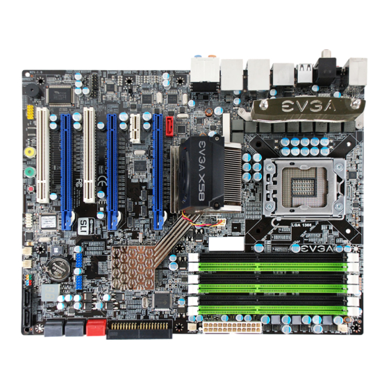
EVGA X58 SLI Motherboard EVGA X58 SLI Motherboard The EVGA X58 SLI Motherboard with the Intel X58 and ICH10R chipset is a PCI Express, SLI-ready motherboard. Figure 1 shows the motherboard and Figures 2 shows the back panel connectors. EVGA... -
Page 15: Figure 1. Evga X58 Sli Motherboard Layout
1394a Connector 21. Front Panel Audio Connector – l a i l a i Debug LED Display - CPU Temperature 19. PCI Express 2.0 Slots Monitor Figure 1. EVGA X58 SLI Motherboard Layout EVGA | 14... -
Page 16: Figure 2. Chassis Backpanel Connectors
EVGA X58 SLI Motherboard 1. PS/2 Keyboard Port 2. USB 2.0 Ports (Eight) 3. Clear CMOS Button 4. Coaxial SPDIF Output 5. Optical SPDIF Output 6. IEE1394a (Firewire) Port 7. eSATA Port 8. Dual LAN Ports with LEDs to indicate status:... -
Page 17: Hardware Installation
To reduce the risk of fire, electric shock, and injury, always follow basic safety precautions. Remember to remove power from your computer by disconnecting the AC main source before removing or installing any equipment from/to the computer chassis. EVGA | 16... -
Page 18: Preparing The Motherboard
EVGA X58 SLI Motherboard Preparing the Motherboard Installing the CPU Be very careful when handling the CPU. Hold the processor only by the edges and do not touch the bottom of the processor. Unhook the socket lever by pushing down and away from the socket. -
Page 19: Installing The Cpu Fan
There are many different fan types that can be used with this motherboard. Follow the instruction that came with you fan assembly. Be sure that the fan orientation is correct for your chassis type and your fan assembly. EVGA | 18... -
Page 20: Installing System Memory (Dimms)
EVGA X58 SLI Motherboard Installing System Memory (DIMMs) Your new motherboard has six 240-pin slots for DDR3 memory. These slots support 256 MB, 512 MB, 1GB, 2GB, 4GB DDR3 technologies. There must be at least one memory bank populated to ensure normal operation. Use the following the recommendations for installing memory. -
Page 21: Installing The Motherboard
Before installing the motherboard, install the I/O shield from the inside of the chassis. Press the I/O shield into place and make sure it fits securely. If the I/O shield does not fit into the chassis, you would need to obtain the proper size from the chassis supplier. EVGA | 20... -
Page 22: Securing The Motherboard Into A System Case
EVGA X58 SLI Motherboard Securing the Motherboard into a System Case Most system cases have a base with mounting studs or spacers to allow the motherboard to be secured to the chassis and help to prevent short circuits. If there are studs that do not align with a mounting hole on the motherboard, it is recommended that you remove that stud to prevent the possibility of a short circuit. -
Page 23: 24-Pin Atx Power (Pw1)
PW1 connector Plug power cable from system power supply to PW1 Card edge Figure 3. PW1 Motherboard Connector Table 1. PW1 Pin Assignments Connector Signal Signal +3.3V +3.3V +3.3V -12V PS_ON PWROK RSVD +5V_AUX +12V +12V +3.3V EVGA | 22... -
Page 24: 8-Pin Atx 12V Power (Pw12)
EVGA X58 SLI Motherboard 8-pin ATX 12V Power ( PW12 PW12 , the 8-pin ATX 12V power connection, is used to provide power to the CPU. Align the pins to the connector and press firmly until seated. Connecting IDE Hard Disk Drives The IDE connector supports Ultra ATA 133/100 IDE hard disk drives. -
Page 25: Connecting Serial Ata Cables
Connect the locking cable end to the motherboard connector. SATA 2 (bottom) SATA 0 (bottom) SATA 8 (bottom) Connect the end without the lock SATA 3 (top) SATA 1 (top) SATA 9 (top) to the SATA device. SATA 7 SATA 6 (e-SATA) EVGA | 24... -
Page 26: Connecting Internal Headers
EVGA X58 SLI Motherboard Connecting Internal Headers Front Panel Header The front panel header on this motherboard is one connector used to connect the following four cables. (see Table 2 for pin definitions): PWRLED Attach the front panel power LED cable to these two pins of the connector. -
Page 27: Ieee1394A (Firewire)
Connect the end of the cable(s) to the IEEE1394a headers on the motherboard. Table 3. IEEE 1394a Connector Pins Connector Signal TPA+ IEEE 1394a Connector TPA- TPB+ TPB- +12V +12V Empty Card Edge EVGA | 26... -
Page 28: Usb Headers
EVGA X58 SLI Motherboard USB Headers This motherboard contains eight (8) USB 2.0 ports that are exposed on the rear panel of the chassis (Figure 2). The motherboard also contains two 10-pin internal header connectors onboard that can be used to connect an optional external bracket containing four (4) USB 2.0... -
Page 29: Audio
Front Audio, the Rear Audio. The front Audio supports re-tasking function. Table 5. Front Audio Connector Connector Signal PORT1_L Front Audio Connector AUD_GND PORT1_R PRECENCE_J PORT2_R SENSE1_RETURN SENSE_SEND Empty Card Edge PORT2_L SENSE2_RETURN EVGA | 28... -
Page 30: Fan Connections
EVGA X58 SLI Motherboard Fan Connections There are six fan connections on the motherboard. The fan speed can be detected and viewed in the section of the CMOS Setup. The PC Health Status fans are automatically turned off after the system enters S3, S4 and S5 mode. -
Page 31: Com1
COM device to the other side of the cable. Expansion Slots The EVGA X58 SLI Motherboard contains six (6) expansion slots, four (4) PCI Express slots and two (2) PCI slots. For a full list of PCI Express graphic cards supported by this motherboard, visit: www.EVGA.com/Products... -
Page 32: Pci Slots
EVGA X58 SLI Motherboard PCI Slots The two PCI slots support many expansion cards such as a LAN card, USB card, SCSI card and other cards that comply with PCI specifications. When installing a card into the PCI slot, be sure that it is fully seated. Secure the card’s metal bracket to the chassis back panel with the screw used to hold the blank cover. -
Page 33: Onboard Buttons
The POWER button with LED indicates the system’s status. When the system is powered on, the LED remains a solid green. The RESET button with an integrated LED indicates the activity status of the hard disk drives and will flicker accordingly. RESET POWER Clear CMOS Button Button Button EVGA | 32... -
Page 34: Post Port Debug Led And Led Status Indicators
EVGA X58 SLI Motherboard Post Port Debug LED and LED Status Indicators Post Port Debug LED Provides two-digit POST codes to show why the system may be failing to boot. It is useful during troubleshooting situations. This Debug LED will also display current CPU temperatures after the system has fully booted into the Operating System. -
Page 35: Configuring The Bios
Setup menus. Descriptions of the BIOS parameters are also provided. This section includes the following information: Enter BIOS Setup Main Menu Standard CMOS Features Advanced BIOS Features Integrated Peripherals Power Management Setup PnP/PCI Configurations PC Health Status Frequency/Voltage Control EVGA | 34... -
Page 36: Enter Bios Setup
To go back to the previous menu, press Note: that on the BIOS screens all data in white is for information only, data in yellow is changeable, data in blue is non-changeable, and data in a red box is highlighted for selection. EVGA... -
Page 37: Figure 4. Bios Cmos Setup Utility Main Menu
Use this menu to configure power management, power on, and sleep features. PnP/PCI Configurations Use this menu to modify the system’s Plug-and-Play and PCI configurations. PC Health Status Use this menu to monitor the real-time system status of your PC, including temperature, voltages, and fan speed. EVGA | 36... - Page 38 Use this command to set, change, and disable the password used to access the BIOS menu. Save & Exit Setup Use this command to save settings to CMOS and exit setup. Exit Without Saving Use this command to abandon all setting changes and exit setup. EVGA...
-
Page 39: Standard Cmos Features Menu
F7:Optimized Defaults Figure 5. Standard CMOS Features Menu Note that all data in white is for information only, data in yellow is changeable, data in blue is non-changeable, and data in a red box is highlighted for selection. EVGA | 38... -
Page 40: Date And Time
[None] SATA 2 [None] SATA 3 [None] SATA 4 [None] SATA 5 [None] Press ENTER to display SATA Channel sub-menu IDE Auto-Detect [Press Enter] Extended IDE Drive [None} Access Mode Auto Capacity 0 MB Cylinder Precomp Landing Zone Sector EVGA... - Page 41 Key in a DEC number : For HDD less than 528 MB. :Move ENTER:Accept ESC:Abort For HDD greater than 528 MB and supporting LBA (Logical Block Addressing). Large For HDD greater than 528 MB but not supporting LBA. Auto Recommended mode. EVGA | 40...
-
Page 42: Halt On
1048576K BIOS POST determines the amount of base (or conventional) memory installed in the system. Extended Memory BIOS determines how much extended memory is present during the POST. Total Memory This value represents the total memory of the system. EVGA... -
Page 43: Advanced Bios Features
F7:Optimized Defaults Figure 6. Advanced BIOS Features Menu Note: That all data in white is for information only, data in yellow is changeable, data in blue is non-changeable, and data in a red box is highlighted for selection. EVGA | 42... -
Page 44: Hard Disk Boot Priority
First Boot Device Removable ..[ ] Hard Disk ..[ ] CDROM ..[ ] Legacy LAN ..[ ] Disabled ..[ ] :Move ENTER:Accept ESC:Abort EVGA... -
Page 45: Boot Other Device
Select to require a password to gain Setup access to the CMOS Setup screen. Select to require a password to System access the CMOS Setup screen and when the system boots. EVGA | 44... -
Page 46: Integrated Peripherals Menu
Main Level USB Device Setting [Press Enter] :Move Enter:Select +/-/PU/PD:Value F10:Save ESC:Exit F1:General Help F5:Previous Values F6:Fail-Safe Defaults F7:Optimized Defaults Figure 7. Integrated Peripherals Menu Legacy Devices Press Enter to display the Legacy Devices menu. Onboard Serial Port 1 [3F8/IRQ4] EVGA... -
Page 47: Onchip Pata/Sata Device
This function allows you to enable JMB362 SATA Controller for SATA port 6/7 control. The options are Auto, Enabled and Disabled. JMB363 SATA/PATA Controller This function allows you to enable JMB363 SATA Controller for IDE & SATA port control. The options are Auto, Enabled and Disabled. EVGA | 46... -
Page 48: Onboard Device
Boot ROM for booting from LAN. TI 1394 Setting This function allows you to enable or disable the IEEE1394 (Firewire) interface. P80 Show CPU Temp. When this function is enabled the onboard Post Port LED will display the CPU temperature. EVGA... -
Page 49: Usb Device Settings
Use this function to enable or disable support for USB keyboard under DOS. USB Mouse Function Use this function to enable or disable support for USB mouse under DOS USB Storage Function Use this function to enable or disable legacy support of USB Mass Storage EVGA | 48... -
Page 50: Power Management Setup Menu
Enter:Select +/-/PU/PD:Value F10:Save ESC:Exit F1:General Help F5:Previous Values F6:Fail-Safe Defaults F7:Optimized Defaults Figure 8. Power Management Setup Menu ACPI Function This function on the Power Management Setup menu allows you to enable or disable the ACPI function. EVGA | 49... -
Page 51: Acpi Suspend Type
This function on the Power Management Setup menu allows you to enable or disable the Power-on by alarm function. Set to to prevent power- [Disable] on by alarm. When set to , you can manually put in the day of the [Enable] month and the time of the alarm. EVGA | 50... -
Page 52: Power On Function
This function enables your computer to automatically restart or return to its last operating status after power returns from a power failure. Off: The system stays off after a power failure. On: The system stays on after a power failure EVGA... -
Page 53: Pnp/Pci Configuration Menu
PnP/PCI Configuration Menu Init Display First This function on the PnP/PCI Configuration menu allows you to define if the initial display is in the PCI slot or in the PCI Express slot. Options are [PCI Slot] [PCIEx]. EVGA | 52... -
Page 54: Reset Configuration
. With this field enabled, press Enter to see options. [Manual] IRQ-5 assigned to [PCI Device] IRQ-9 assigned to [Reserved] IRQ-10 assigned to [PCI Device] IRQ-11 assigned to [PCI Device] IRQ-14 assigned to [PCI Device] IRQ-15 assigned to [PCI Device] EVGA... -
Page 55: Pci/Vga Palette Snoop
TLP payload size (in bytes) for the PCI Express devices. Use the Page Up Page Down keys to scroll through sizes or enter the number using – keys to go up and down the list of the keyboard numbers or use the sizes. EVGA | 54... -
Page 56: Pc Health Status Menu
F1:General Help F5:Previous Values F6:Fail-Safe Defaults F7:Optimized Defaults Figure 10. PC Health Status Menu All of the values shown in are dynamic and change as the speed and Blue voltages of the various components change with system usage. EVGA | 55... -
Page 57: Smartfan Function
To set the fan speed to a constant rate, select and then enter the speed from 0% to 100%. [Manual] Set the desired speed for the Power and Chassis fans from 0% to 100%. The system defaults to 100%. EVGA | 56... -
Page 58: Frequency/Voltage Control Menu
CPU Feature [Press Enter] CPU Clock Ratio [22X] CPU Host Frequency(Mhz) [133] Main Level Spread Spectrum [Disabled] PCIE Frequency(Mhz) [100] EVGA VDroop control [With VDroop] CPU VCore [1.25000V] 1.25000V CPU VTT Voltage [Auto] 1.100V CPU PLL Vcore [Auto] 1.800V DIMM Voltage [Auto] 1.500V... -
Page 59: Memory Feature
1 way, 2 way, 3 way, 4 way, 5 way and 6 way. Rank Interleave Setting This function is allows you to select the Rank Interleave Setting. The options are 1 way, 2 way and 4 way. EVGA | 58... -
Page 60: Cpu Feature
This function is set the command timing setting on a per clock unit basis. The options are Auto, 1T and 2T. CPU Feature Select from the Frequency/Voltage Control menu and press CPU Feature to display the CPU Feature menu. Enter EVGA... -
Page 61: Figure 13. Cpu Feature Menu
This function allows you to select the lowest C state supported according as CPU and MB. The options are Auto, Disabled, C1, C1E, C3 and C6. Execute Disable Bit When this function is disabled, it forces the XD feature flag to always return to zero (0). EVGA | 60... -
Page 62: Cpu Clock Ratio
This function is allows you to select the QPI Frequency. The options are Auto, 4.800 GT/s, 5.866 GT/s and 6.400 GT/s. CPU Clock Ratio This value changes the CPU Frequency value depending on the value you choose. Use the Page Up and Page Down keys to scroll through the options. EVGA... -
Page 63: Cpu Host Frequency (Mhz)
This item reduces the EMI generated. The options are Disabled and Enabled. EVGA VDroop control EVGA VDroop control is a safety measure by motherboards to protect the CPU. Select to [With VDroop] to calibrate CPU VDroop or select to [Without VDroop] to disable this function. -
Page 64: Dimm Dq Vref
This function defines the core voltage level for the Intel ICH chip. Use the Page Up and Page Down keys to select a voltage or select [Auto] to automatically set the voltage. CPU Thermal Trip This function allows you to set the CPU Thermal Trip function. The options are Enabled and Disabled. EVGA... -
Page 65: Pwm Frequency
PWM Frequency This function allows you to select the PWM frequency. For the following options, higher is cleaner, lower is more energy efficient: 806KHz, 935KHz, 1057KHz. EVGA | 64... -
Page 66: Installing Drivers And Software
Windows XP 32bit and 64bit and is Vista-capable. The kit comes with a CD that contains utilities, drivers, and additional software. The CD that has been shipped with the EVGA X58 SLI Motherboard contains the following software and drivers: Chipset Drivers... -
Page 67: Appendix A. Post Codes For The Evga X58 Sli Motherboard
Appendix A. POST Codes for the EVGA X58 SLI Motherboard This section provides the Award POST Codes (Table 6) for the EVGA X58 SLI Motherboard during system boot up. The POST Codes are displayed on the Debug LED readout located directly onboard the motherboard. - Page 68 HPM init Init Heuristic Power Management (HPM) Reserved Program Early Programming of chipset registers chipset Init PNP Init PNP Shadow VBIOS Shadow system/video BIOS Clock Gen Init onboard clock generator and sensor Setup BDA Setup BIOS DATA AREA (BDA) Reserved EVGA...
- Page 69 Verify 8259 Channel 1 masked interrupts by Mask alternately turning off and on the interrupt lines. Reserved Test 8259-2 Verify 8259 Channel 2 masked interrupts by Mask alternately turning off and on the interrupt lines. Reserved Reserved EVGA | 68...
- Page 70 CPU display Detect CPU speed and display CPU vendor specific version string and turn on all necessary CPU features Reserved PnP Init PnP logo and PnP early init Display Reserved Setup Virus Setup virus protect according to Protect Setup Reserved EVGA...
- Page 71 Initialize floppy disk drive Floppy Reserved FDD install Install FDD and setup BIOS data area parameters Reserved Reserved Reserved Initialize Hard Initialize hard drive controller Drive Reserved Detect HDD IDE device detection Reserved Detect serial Initialize serial ports. EVGA | 70...
- Page 72 USB Final Init Final USB initialization Reserved Reserved Reserved Setup ACPI Setup ACPI tables tables Reserved Option ROM Scan for Option ROMs Detect Reserved Enable Parity Enable Parity Check Check Reserved IRQ12 Enable Enable IRQ12 if mouse present Reserved EVGA...
- Page 73 If interrupt occurs in protected mode. Unclaimed NMI If unmasked NMI occurs, display Press F1 to disable NMI, F2 reboot. Program MCP To program chipset from defaults values E1-EF Setup Pages E1- Page 1, E2 - Page 2, etc. Boot EVGA | 72...
-
Page 74: Evga Glossary Of Terms
Configuring the BIOS EVGA Glossary of Terms ACPI - Advanced Configuration and Power Interface AFR – Alternate Frame Rendering APIC - Advanced Programmable Interrupt Controller BIOS - Basic Input Output System CD-ROM - Compact Disc Read-Only Memory CMOS - Complementary Metal-Oxide Semiconductor CPU –... - Page 75 RAID - Redundant Array of Inexpensive Disks RGB - Red Green Blue SATA - Serial Advanced Technology Attachment SB - Southbridge SCSI - Small Computer System Interface SFR – Split Frame Rendering SLI - Scalable Link Interface SPD - Serial Presence Detect EVGA | 74...
- Page 76 Configuring the BIOS SPDIF - Sony/Philips Digital Interconnect Format SPP - System Platform Processors TCP/IP - Transmission Control Protocol/Internet Protocol USB - Universal Serial Bus VDroop - V-core Voltage Drop VGA - Video Graphics Array EVGA...
Need help?
Do you have a question about the RB-132-BL-E758-RX - X58 SLI - Recert and is the answer not in the manual?
Questions and answers