Sign In
Upload
Download
Table of Contents
Contents
Add to my manuals
Delete from my manuals
Share
URL of this page:
HTML Link:
Bookmark this page
Add
Manual will be automatically added to "My Manuals"
Print this page
×
Bookmark added
×
Added to my manuals
Manuals
Brands
EVGA Manuals
Motherboard
121-BL-E756
User manual
EVGA 121-BL-E756 User Manual
Evga motherboard user's manual
Hide thumbs
1
Table Of Contents
2
3
4
5
6
7
8
9
10
11
12
13
14
15
16
17
18
19
20
21
22
23
24
25
26
27
28
29
30
31
32
33
34
35
36
37
38
39
40
41
42
43
44
45
46
47
48
49
50
51
52
53
54
55
56
57
58
59
60
61
62
63
64
65
66
67
68
69
70
71
72
73
74
page
of
74
Go
/
74
Contents
Table of Contents
Bookmarks
Table of Contents
Table of Contents
EVGA X58 SLI Micro Motherboard
Parts NOT in the Kit
Intentions of the Kit
EVGA X58 SLI Micro Motherboard
Motherboard Specifications
Unpacking and Parts Descriptions
Unpacking
Equipment
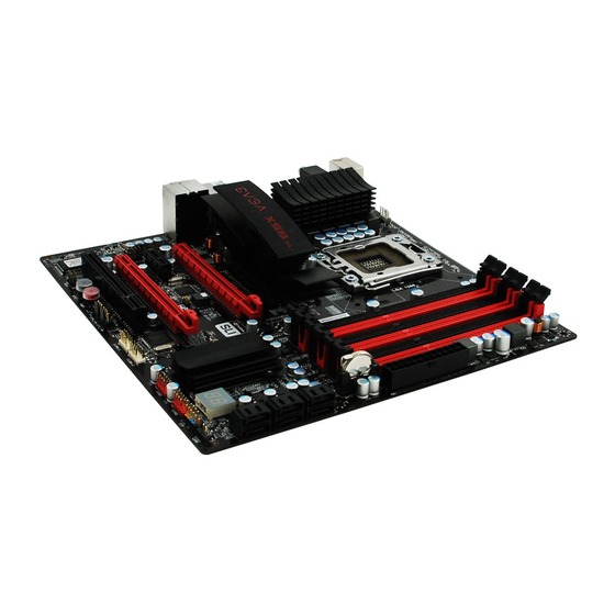
EVGA X58 SLI Micro Motherboard
Figure 1. EVGA X58 SLI Micro Motherboard Layout
Figure 2. Chassis Backpanel Connectors
Hardware Installation
Safety Instructions
Preparing the Motherboard
Installing the CPU
Installing the CPU Fan
Installing System Memory (Dimms)
Installing the Motherboard
Installing the I/O Shield
Securing the Motherboard into a System Case
Connecting Cables
24-Pin ATX Power (PW1)
Figure 3. PWR1 Motherboard Connector
8-Pin ATX 12V Power (PW12)
Connecting Serial ATA Cables
Connecting Internal Headers
Front Panel Header
Ieee1394A (Firewire)
USB Headers
Audio
Fan Connections
Expansion Slots
PCI Slots
PCI Express X1 Slots
PCI Express X16/X8/X4 Slots
Onboard Buttons
Clear CMOS Button
RESET and POWER Button
Post Port Debug LED and LED Status Indicators
Post Port Debug LED
LED Status Indicators
Configuring the BIOS
Enter BIOS Setup
Main Menu
Figure 4. BIOS CMOS Setup Utility Main Menu
Standard CMOS Features Menu
Figure 5. Standard CMOS Features Menu
Date and Time
SATA Channel
Halt on
Memory
Advanced BIOS Features
Figure 6. Advanced BIOS Features Menu
CD-ROM Device Priority
First/Second/Third Boot Device
Hard Disk Boot Priority
Boot Other Device
Boot up Numlock Status
Security Option
Integrated Peripherals Menu
Figure 7. Integrated Peripherals Menu
Onboard Device
Onboard PATA/SATA Device
USB Device Settings
Power Management Setup Menu
ACPI Function
Figure 8. Power Management Setup Menu
ACPI Suspend Type
Run VGABIOS if S3 Resume
Soft-Off by PWR-BTTN
Wake-Up by PCI Card
USB KB Wake-Up from S3
Resume by Alarm
POWER on Function
Hot Key Power on
PWRON after PWR-Fail
Pnp/Pci Configuration Menu
Init Display First
Figure 9. Pnp/Pci Configuration Menu
Reset Configuration
Resources Controlled by
IRQ Resources
PCI/VGA Palette Snoop
INT Pin 1/2/3/4/5/6/7/8 Assignment
Maximum Payload Size
PC Health Status Menu
Figure 10. PC Health Status Menu
Smartfan Function
Frequency/Voltage Control Menu
Figure 11. Frequency/Voltage Control
Figure 12. Memory Feature Menu
Memory Feature
Memory Frequency
EVGA Vdroop Control
Figure 13. Voltage Control Menu
Voltage Control
CPU Feature
Execute Disable Bit
Figure 14. CPU Feature Menu
Installing Drivers and Software
Windows Xp/Vista Driver Installation
Appendix A. POST Codes for the EVGA X58 SLI Micro Motherboard
Evga Glossary of Terms
Advertisement
Quick Links
1
Motherboard Specifications
Download this manual
Table of
Contents
Previous
Page
Next
Page
1
2
3
4
5
Advertisement
Table of Contents
Need help?
Do you have a question about the 121-BL-E756 and is the answer not in the manual?
Ask a question
Questions and answers
Related Manuals for EVGA 121-BL-E756
Motherboard EVGA 121-BL-E756-TR Visual Manual
Evga x58 sli micro motherboard visual guide (2 pages)
Motherboard EVGA P55 Micro V User Manual
P55 chipset based motherboard (77 pages)
Motherboard Evga P55V Specifications
(1 page)
Motherboard EVGA 121-LF-E652-KR Visual Manual
Evga motherboard visual guide (2 pages)
Motherboard Evga nForce 750i SLI Quick Install Manual
(2 pages)
Motherboard EVGA P55 LE User Manual
Evga motherboard user's guide (44 pages)
Motherboard EVGA nForce 123-YW-E175 User Manual
Evga mainboard user's manual (58 pages)
Motherboard EVGA 120-SB-E682-KR User Manual
User guide (36 pages)
Motherboard EVGA 122-M2-NF59-TR User Manual
User manual (67 pages)
Motherboard EVGA 680i - nForce LT SLI Motherboard User Manual
Lt sli motherboard with intel processor (80 pages)
Motherboard EVGA P55 LE Specification
Pdf spec sheet (1 page)
Motherboard EVGA Z68 SLI Micro Specifications
Pdf spec sheet (2 pages)
Motherboard Evga Z68 SLI Micro Specifications
120-sb-e682 (2 pages)
Motherboard Evga P55V Quick Manual
(1 page)
Motherboard EVGA X570 FTW Introduction
(2 pages)
Motherboard EVGA Z590 FTW WIFI User Manual
(163 pages)
This manual is also suitable for:
X58 sli micro
121-bl-e756-tr
Table of Contents
Save PDF
Print
Rename the bookmark
Delete bookmark?
Delete from my manuals?
Login
Sign In
OR
Sign in with Facebook
Sign in with Google
Upload manual
Upload from disk
Upload from URL


Need help?
Do you have a question about the 121-BL-E756 and is the answer not in the manual?
Questions and answers