
Related Manuals for EVGA H370 Stinger


Summary of Contents for EVGA H370 Stinger
- Page 1 EVGA H370 Stinger (111-CS-E371) User Guide EVGA H370 Stinger Specs and Initial Installation - 1 -...
-
Page 2: Table Of Contents
Motherboard Specifications ....................- 6 - Unpacking and Parts Descriptions ..................- 8 - EVGA H370 Stinger Motherboard LED reference .............. - 9 - EVGA H370 Stinger Motherboard Component Legend............. - 10 - Component Legend Descriptions ..................- 12 - PCIe Slot Breakdown (Coffee Lake-S) ................ - Page 3 System turns on, but fails to successfully POST .............. - 113 - Have a question not covered above, or want some online resources? ......- 115 - EVGA Glossary of Terms ....................- 116 - Compliance Information ..................- 119 -...
-
Page 4: Evga H370 Stinger
By using a careful balance of performance and features, the H370 Stinger gets you straight to the point. Lastly, a motherboard is only as good as its BIOS, and the EVGA H370 Stinger features an updated UEFI\BIOS GUI with a focus on enthusiast features and functionality in a lean, straight-forward package. -
Page 5: Parts Not In The Kit
Monitor Optical Drive (Optional) EVGA assumes you have purchased all the necessary parts needed to allow for proper system functionality. For a full list of supported CPUs on this motherboard, please visit www.evga.com/support/motherboard Intentions of the Kit... -
Page 6: Motherboard Specifications
EVGA H370 Stinger (111-CS-E371) Motherboard Specifications Size: Mini-ITX form-factor of 6.7 inches x 6.7 inches (170.18x170.18mm) Microprocessor support: Intel Socket 1151 Processor (Coffee Lake-S) ® Operating Systems: Supports Windows 10 64bit System Memory support: Supports Dual-Channel DDR4 up to 2667MHz+ (OC) Supports up to 32GB of DDR4 memory. - Page 7 EVGA H370 Stinger (111-CS-E371) Power Functions: Supports ACPI (Advanced Configuration and Power Interface) Supports S0 (normal), S3 (suspend to RAM), S4 (Suspend to disk - depends on OS), and S5 (soft - off) PCIe Expansion Slots: 1x PCIe x16 slot PCIe 3.0 Support:...
-
Page 8: Unpacking And Parts Descriptions
EVGA H370 Stinger (111-CS-E371) Unpacking and Parts Descriptions The following accessories are included with the EVGA H370 Stinger Motherboard: - 8 -... -
Page 9: Evga H370 Stinger Motherboard Led Reference
EVGA H370 Stinger (111-CS-E371) EVGA H370 Stinger Motherboard LED reference The EVGA H370 Stinger Motherboard has one LED to indicate power and connectivity. Below is the location of the LED and its function. LED Legend 5VSB 1. +5VSB a. White: Voltage present (Does not mean PSU is outputting in-spec, only... -
Page 10: Evga H370 Stinger Motherboard Component Legend
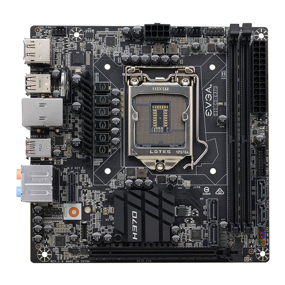
EVGA H370 Stinger (111-CS-E371) EVGA H370 Stinger Motherboard Component Legend The EVGA H370 Stinger Motherboard with the Intel H370 and PCH Chipset. ® Figure 1 shows the motherboard and Figure 2 shows the back panel connectors FIGURE 1. H370 Stinger Motherboard Layout Component Legend 1. - Page 11 EVGA H370 Stinger (111-CS-E371) Figure 2. Chassis Rear Panel Connectors I/O Hub Legend 1. DisplayPort 1.2 (iGPU) 4. Intel i219V Gigabit NIC 7. Optical Audio Out 2. HDMI 2.0 Output (iGPU) 5. USB 3.1 Gen 1 Ports 8. Analog Audio Jacks 3.
-
Page 12: Component Legend Descriptions
EVGA H370 Stinger (111-CS-E371) Component Legend Descriptions 1. CPU Socket 1151 This is the interface for the Central Processing Unit (CPU), and supports Core ™ Series i3, i5, and i7 models compatible with the Intel LGA1151 Socket, based ® on Coffee Lake-S architecture. - Page 13 EVGA H370 Stinger (111-CS-E371) 5. 24-pin ATX power connector The main power for the motherboard is located on the right side of the board and perpendicular to the PCB; this is also described as a “Vertical” connector (See Page 31 for more specifics to the connector itself, and associated wiring/pinouts).
- Page 14 EVGA H370 Stinger (111-CS-E371) 9. M.2 Socket 1 Key-E 32mm M.2 Key-E sockets are generally used for WiFi and Bluetooth cards. Key-E and Key-M connectors are different, meaning that devices are not interchangeable between sockets. 10. PCIe Slot x16* PCIe x16 slots are primarily used for video cards. These full-length slots will provide 8 or 16 lanes of bandwidth to a full-size card, and are backwards- compatible with x8, x4, and x1-length cards.
- Page 15 EVGA H370 Stinger (111-CS-E371) panel USB, auxiliary ports that mount in the card slots, and also some devices that directly connect to the header. USB 3.1 Gen 1 standard available current is 900mA @ 5V for unpowered devices. If your USB device requires more power than this, it is recommended to attach a powered USB Hub.
- Page 16 USB, auxiliary ports that mount in the card slots, and certain devices that directly connect to the header. The USB 3.1 Header on the H370 Stinger is a shielded USB 3.1 Header and supports up to 10Gb/s with USB3.1 Gen2.
-
Page 17: Pcie Slot Breakdown (Coffee Lake-S)
EVGA H370 Stinger (111-CS-E371) Card Slots The H370 Stinger features one x16 PCIe slot, one Socket 3 Key-M M.2 80mm (backwards compatible with Key-M 60mm, and 42mm devices), and one vertical Socket 1 Key-E M.2. PCIe Slot Breakdown (Coffee Lake-S) ™... -
Page 18: Preparing The Motherboard
Preparing the Motherboard Installing the CPU Note: EVGA strongly recommends that you completely disconnect AC power from your power supply prior to changing your CPU. This ensures the motherboard will use the correct startup procedure for all onboard devices. If AC power is not disconnected, the replacement is still supported, but may require additional reboots to boot successfully. -
Page 19: Installing The Cpu Cooling Device
EVGA H370 Stinger (111-CS-E371) 3. Align the notches on the CPU to the notches in the socket, and lower the processor straight down into the socket. Note: The gold triangle key on the CPU should match the triangle key on the load plate. -
Page 20: Installing System Memory
EVGA H370 Stinger (111-CS-E371) Installing System Memory Your H370 Stinger has (2) 288-pin slots for DDR4 memory. These slots support 4GB, 8GB and 16GB DDR4 DIMMs. There must be at least one memory slot populated for the board to boot and operate. -
Page 21: Installing The I/O Shield And I/O Cover
EVGA H370 Stinger (111-CS-E371) Installing the I/O Shield and I/O Cover The motherboard kit comes with an I/O shield that is used to block internal components from dust and foreign objects, while also promoting correct airflow within the chassis. Before installing the motherboard, install the I/O shield from the inside of the chassis. -
Page 22: Securing The Motherboard Into A System Case
6. See the picture below for a zoomed-in view of a hole to place over a standoff, as well as the locations of standoff holes for the H370 Stinger. - 22 -... - Page 23 EVGA H370 Stinger (111-CS-E371) 1. All safe locations to secure the board to a standoff are circled in red. 2. Keep in mind that when the screws are installed, but not fully tightened, the motherboard should have 1-2mm of movement; this can help when mounting cards or tight-fits with other components.
-
Page 24: Installing M.2 Devices
80mm interval for the Socket 3 slot. Next add one thermal pad – included with the H370 Stinger accessories – to the outlined area to the right. 2. After adding the thermal pad, the motherboard will look like the image below. This thermal pad will assist with cooling your M.2 Key-M device. -
Page 25: Incorrect M.2 Installation Example
EVGA H370 Stinger (111-CS-E371) 3. Insert the M.2 device at a slight angle of approximately 45 degrees to the board. This will allow the contacts (colloquially called “Gold Fingers”) to seat completely into the slot. If the device is fully seated,... -
Page 26: Installing M.2 Key-E Socket 1 Devices
M.2 Key-E Socket 1 slots are used to install WiFi or Bluetooth cards. Although the orientation of the slot(s) may vary on different motherboards, the H370 Stinger uses a right-angle adapter near the I/O ports. Please see Page 10 to locate the slot. - Page 27 EVGA H370 Stinger (111-CS-E371) 1. (Left) Remove the circled nut and screw from the bracket and briefly set aside; the bracket will be mounted to the circled area. (Middle) Align the bracket parallel to the M.2 Key-E Socket, use a Phillips #1 screwdriver to help align the screw over the mounting hole, and loosely fasten the nut from underneath the motherboard.
-
Page 28: Tested Cpu And Memory
This list of tested CPUs is accurate as of the time of print. For a full list of tested CPUs and Memory, including updates, go to https://www.evga.com/support/motherboard/ and select the EVGA H370 Stinger from the list. Tested M.2 Key-M M.2 Key M (SSD) :... -
Page 29: Tested M.2 Key-E
EVGA H370 Stinger (111-CS-E371) Tested M.2 Key-E M.2 Key E (WiFi) Brand Part Number WiFi Support Intel 8260NGW BT 4.1 /802.11ac Intel 8265NGW BT 4.2 /802.11ac Intel 9560NGW BT 5.0 /802.11ac AzureWave AW-NB165NF BT 4.0 /802.11 B, G, N - 29 -... -
Page 30: Connecting Cables
Connecting Cables Note: the following images do not necessarily represent the physical orientation of their respective headers on the EVGA H370 Stinger. Rather, these graphical representations are designed to provide a basic physical footprint and the cable pinouts for each component. - Page 31 Firmly plug the power supply cable into the connector and make sure it is secure. The 24-pin Power Connector may be standard or right-angled depending on your motherboard model. The H370 Stinger motherboard uses a standard 24pin ATX connector. - 31 -...
- Page 32 EVGA H370 Stinger (111-CS-E371) EPS 8-pin 12V Power (PWR , the 8-pin ATX 12V power connection(s), is used to provide EPS PWR 8P power to the CPU. Align the pins to the connector and press firmly until seated. Please remember to make sure that the tab on the EPS socket is aligned with the release clip on the cable.
- Page 33 EVGA H370 Stinger (111-CS-E371) Front Panel Header The front panel header on this motherboard is used to connect the following four cables: PWRLED Attach the front panel power LED cable to these two pins of the connector. The Power LED indicates the system’s status. When the system is powered on, the LED will be on.
- Page 34 EVGA H370 Stinger (111-CS-E371) Fan Header This motherboard line only has 4-pin fan headers, which are backwards compatible with 3-pin fan connectors. Fans are controlled via PWM controls. The headers have an absolute safe power limit of 1 Amp @ 12 Volts (12 Watts).
- Page 35 This motherboard contains USB3.1 Gen2, USB3.1 Gen1, and USB2.0 ports that are exposed on the rear panel of the chassis. The H370 Stinger contains 1x 20pin internal header, which can support 1 USB3.1 Type-C front-panel connector or device. - 35 -...
- Page 36 EVGA H370 Stinger (111-CS-E371) The motherboard contains 1x 19-pin internal header connectors onboard that can be used to connect an optional external devices containing up to two (2) USB3.1 Gen 1 ports. Please note that these headers are often referred to as USB3.0 internal ...
- Page 37 EVGA H370 Stinger (111-CS-E371) The motherboard contains 2x 9-pin internal header connectors onboard that can be used to connect optional external devices containing up to four (4) USB 2.0 ports. Secure the bracket to either the front or rear panel of your chassis (not ...
- Page 38 EVGA H370 Stinger (111-CS-E371) Front Panel Audio Header Front panel audio supports HD Audio for stereo/gaming headphones or 2.1 speakers, and a Mic. - 38 -...
- Page 39 EVGA H370 Stinger (111-CS-E371) Drive Headers (SATA) SATA III 6 Gb/s is the current standard for HDD/SSD/Optical interface. These cables are the data interconnect for the motherboard. Your HDD/SSD/Optical interface will still require a separate power connection from your power supply.
-
Page 40: First Boot
EVGA H370 Stinger (111-CS-E371) First Boot When you power the system on for the first time (or after a BIOS update/reset) it may take a little longer than expected, and follow with a pause and message on the screen reading “BIOS Checksum error, Press F2 to continue or F12 to enter the BIOS.”... - Page 41 EVGA H370 Stinger (111-CS-E371) prefer, but the XMP will generally get the memory running at the memory manufacturer’s specification with little to no effort. HDD/SSD/M.2 Setup Next, click “Boot” from the menu list at the top. “Boot Option #1” should show the device that you intend to install your operating system.
-
Page 42: M.2 Ssd, Pcie Ssd, And Nvme Ssd Installation Steps
EVGA H370 Stinger (111-CS-E371) M.2 SSD, PCIe SSD, and NVMe SSD Installation steps M.2 is a versatile card module form factor that uses multiple connecter types to connect many types of devices, such as WiFi or SSDs, in a very small and power efficient package. - Page 43 EVGA H370 Stinger (111-CS-E371) a. For Windows 10: Set “Launch Storage OpROM Policy” to “UEFI”. Then set “Launch CSM” to “Disable”. 4. Press F10 to save and exit the BIOS/UEFI. 5. Press Del on reboot to reenter BIOS/UEFI. a. If you are using an SSD-attached via PCIe, proceed to Step 6.
-
Page 44: Internal Raid Controller
EVGA H370 Stinger (111-CS-E371) Internal RAID Controller This section introduces RAID, RAID levels, and the basics of the controller integrated into the PCH. It covers the basics of what RAID does, how RAID works, and why you may or may not want to use RAID. - Page 45 EVGA H370 Stinger (111-CS-E371) its quality, and many other factors; but the number should give you a ballpark estimate on what to expect as a final capacity once formatted. Please see below for examples of what to expect when you build an array of each type.
- Page 46 EVGA H370 Stinger (111-CS-E371) one drive fails, the array fails. It MAY be possible to recover the data but that usually requires a data recovery service, which is not guaranteed and is usually very expensive. RAID0 is typically only limited by the controller; however, you will get severely diminishing performance returns after 4 drives.
- Page 47 EVGA H370 Stinger (111-CS-E371) RAID 0 (4 Drive) P-DRIVE1 P-DRIVE2 P-DRIVE3 P-DRIVE4 P-DRIVE1 P-DRIVE2 P-DRIVE3 P-DRIVE4 DATA-A DATA-B DATA-C DATA-D DATA-A DATA-B DATA-C DATA-D DATA-ABCD DATA-ABCD P-DRIVE1 P-DRIVE2 P-DRIVE3 P-DRIVE4 P-DRIVE1 P-DRIVE2 P-DRIVE3 P-DRIVE4 DATA-A DATA-B DATA-C DATA-D DATA-A DATA-B...
- Page 48 EVGA H370 Stinger (111-CS-E371) The Bad- RAID1 is not a storage capacity-friendly array, because the capacity will be limited to 1 drive. o Due to the capacity available on modern drive solutions, this issue may not be as significant as it once was.
- Page 49 EVGA H370 Stinger (111-CS-E371) Similar to RAID1, or any other current type of array with fault tolerance, a RAID5 array is still usable even while it is experiencing a missing or failed drive resulting in the array functioning in a degraded state. Performance will suffer in a degraded state until the missing drive is replaced and the software rebuild process is completed.
- Page 50 EVGA H370 Stinger (111-CS-E371) L-DRIVE = ≃ 3TB RAID 5 (4 Drive) P-DRIVE1 P-DRIVE2 P-DRIVE3 P-DRIVE4 P-DRIVE1 P-DRIVE2 P-DRIVE3 P-DRIVE4 P-DRIVE1 P-DRIVE2 P-DRIVE3 P-DRIVE4 DATA-A DATA-B DATA-C DATA-A DATA-A DATA-B DATA-C DATA-A DATA-A DATA-B DATA-C DATA-A DATA-B DATA-C DATA-A DATA-B...
- Page 51 L-Drive = DATA-AB L-Drive = DATA-AB While the H370 Stinger controller will support up to a four drive RAID10 array, RAID10 can scale indefinitely provided the controller supports more drives. Every pair of drives adds an additional mirrored node, which increases the theoretical number of failures the array can suffer before a loss of data occurs.
- Page 52 EVGA H370 Stinger (111-CS-E371) In the case of a drive RAID 10 (6 Drive) L-DRIVE = ≃ 3TB failure, the array P-DRIVE1 P-DRIVE2 P-DRIVE3 P-DRIVE4 P-DRIVE5 P-DRIVE6 controller will notify you. When you replace P-DATA-A P-DATA-A P-DATA-B P-DATA-B P-DATA-C P-DATA-C...
- Page 53 EVGA H370 Stinger (111-CS-E371) RAID0+1 : RAID0+1 is a form of nested RAID that was widely used on previous generation boards. Although the H370 Series motherboards do not use this type of array, it is listed here to show the improvements made by RAID10, and to clear up a common misperception that RAID0+1 and RAID10 are the same.
- Page 54 L-Drive = DATA-AB L-Drive = DATA-AB Motherboard controllers that support RAID0+1 (such as older generation EVGA motherboards) will generally support 4 or 6 drive arrays of this type; other controllers can allow this array type to scale indefinitely. Each pair of drives adds to the drive count for the stripes and increases the theoretical volume of failures the array can suffer before a loss of data occurs.
- Page 55 EVGA H370 Stinger (111-CS-E371) As you can see, the L-DRIVE = ≃ 3TB RAID 0+1 (6 Drive) difference between RAID0+1 and RAID10 P-DRIVE1 P-DRIVE2 P-DRIVE3 P-DRIVE4 P-DRIVE5 P-DRIVE6 is significant when DATA-A DATA-B DATA-C DATA-A DATA-B DATA-C looking at how data is stored.
-
Page 56: Configuring The Array
EVGA H370 Stinger (111-CS-E371) Which types of RAID can I use with my setup? 1 Drive – No RAID arrays are supported 2 Drives – RAID0 for speed (do regular backups) or RAID1 for data protection. 3 Drives – RAID0 for speed (do regular backups) or RAID5 for speed and protection. - Page 57 EVGA H370 Stinger (111-CS-E371) RAID mode not only includes the RAID controls, but also shares the same options/functions/commands as AHCI; you may continue using your AHCI devices normally when the SATA Configuration is set to RAID mode. The SATA Information menu shows a list of all drives currently detected by the controller;...
- Page 58 EVGA H370 Stinger (111-CS-E371) Once in the RAID controller, you will see a list of all detected drives and a “Create RAID Volume” button. To begin, click on “Create RAID Volume” or navigate to the button and hit “Enter.” Choose a name for the volume. The controller allows up to 15 characters; you can use numbers and letters, but not special characters.
- Page 59 EVGA H370 Stinger (111-CS-E371) Next, select your intended array type. This can be done by either clicking on the down arrow and clicking on the RAID level you want, or pressing the enter key and using the down arrow to select the RAID level and pressing Enter again. Please see the top half of Page 56 for a quick reference on different RAID levels and RAID types based on your total number of drives.
- Page 60 EVGA H370 Stinger (111-CS-E371) Strip size (also called “block size” in other controllers) can be selected manually at 16k, 32k, 64k, or 128k. The controller will determine the default strip size after looking at your drives and array type. Although there are some limited instances where this must be set manually, it is highly recommended to leave this at default.
-
Page 61: Repairing An Array Within Uefi
EVGA H370 Stinger (111-CS-E371) If your array will be your boot drive, the operating system will normally detect the array and see it as a single drive (this is expected), it *MAY* detect it as a RAID array; either way, the OS installation will show the size of the array, not a single drive, and allow you to install the OS to the array without any further steps. - Page 62 EVGA H370 Stinger (111-CS-E371) your array status and any drives that are not currently configured in a RAID array. The Non-RAID Physical Disks list will display any remaining drives on the controller, whether it is a random storage drive, a boot drive, or a replacement drive installed to replace a failed unit.
- Page 63 EVGA H370 Stinger (111-CS-E371) Next, you will see a list of all attached HDD/SSDs that can be used to rebuild the array. Select the disk, then click on it or press enter. Once the process has started you will see the status change to “Rebuilding.”...
-
Page 64: Irst (Intel Rapid Storage Technology)
EVGA H370 Stinger (111-CS-E371) ® IRST (Intel Rapid Storage Technology) The IRST is the software front-end for the Intel SATA controller. It is recommended ® to install the IRST drivers after installing the Intel Chipset Drivers – the main ®... - Page 65 EVGA H370 Stinger (111-CS-E371) SATA will be selected by default. PCIe primarily refers to PCIe / M.2 based NVMe drives; the same basic steps do apply to both, however. Select SATA, and “Real-time protection (RAID1).” Then, click Next at the bottom of the window.
- Page 66 EVGA H370 Stinger (111-CS-E371) - 66 -...
- Page 67 EVGA H370 Stinger (111-CS-E371) In the Advanced tab, you can select the option to “Initialize Volume,” which will occur after the array is created. If the array is not initialized now, it can be initialized later in “Disk Management.” See Page 74 for Disk Management instructions.
- Page 68 EVGA H370 Stinger (111-CS-E371) Review the summary provided on the confirmation screen. If you are unsure about any selections made, click the “Back” key and make your corrections. When ready, click “Create Volume” at the bottom. This typically takes between a few seconds to a couple minutes depending on the size and complexity of the volume.
- Page 69 EVGA H370 Stinger (111-CS-E371) Once you click the OK button on the RAID creation window you will be brought back to the main window, “Status” tab. If the option to initialize was selected, the initialization status will be shown below, circled in red.
-
Page 70: Repairing An Array Within Irst
EVGA H370 Stinger (111-CS-E371) Repairing an array within IRST This section of the guide will illustrate how to repair a degraded array from within the IRST. For purposes of this guide, we are repairing a degraded RAID 1 array using a third drive plugged into the controller, but not currently in use. - Page 71 EVGA H370 Stinger (111-CS-E371) The “Manage” tab shows the array specifically, and not just the controller as a whole. Next to “Status: Degraded,” left-click the hyperlink labeled “Rebuild to another disk.” This will bring a pop-up window over the IRST showing a list of attached drives that...
- Page 72 EVGA H370 Stinger (111-CS-E371) Select the drive you wish to use for the repair and click the “Rebuild” button. - 72 -...
- Page 73 EVGA H370 Stinger (111-CS-E371) The rebuild process will begin. As with any RAID array with Fault Tolerance, the rebuilding time depends on several factors, such as array size, array type, CPU, etc. You will then see the Rebuild % status in the Manage tab. Once repairs are complete, the array will update to “Status: Normal.”...
-
Page 74: Partitioning And Formatting A Drive
EVGA H370 Stinger (111-CS-E371) Partitioning and Formatting a drive Once you have created your array, either from UEFI or from IRST, you will not initially see your array in “This PC.” This is expected, because even though you have created the array, you have not yet prepared the array to be used. - Page 75 EVGA H370 Stinger (111-CS-E371) After “Disk Management” loads, you’ll see a pop-up to Initialize Disk if you’ve added a new drive or created a new array. Generally, it’s recommended to select “GPT,” unless you need backwards compatibility with an old OS or PC. When you’ve made your choice, click “OK.”...
- Page 76 EVGA H370 Stinger (111-CS-E371) Before you can assign a drive letter to a drive or array, the initialized disk must be partitioned. If you are following this guide and just initialized your drive or array, the New Simple Volume Wizard will automatically pop-up.
- Page 77 EVGA H370 Stinger (111-CS-E371) Leave the size at default to create a partition using the entire volume of disk space, then click “Next.” Select the drive letter you want to represent this drive, then click “Next.” Note: The drive letter does NOT have to be a consecutive letter with previous drive(s).
- Page 78 EVGA H370 Stinger (111-CS-E371) After the quick format is completed, you will see the last Window of the wizard, a summary of the process, then click “Finish.” The drive is now usable. To confirm, go back to File Explorer in Windows. Click on “This PC” and check the drives section.
-
Page 79: Fan Header Dc And Pwm Setup
EVGA H370 Stinger (111-CS-E371) Fan Header DC and PWM setup This motherboard supports 4-pin PWM fans. The CPU1, CPU2, and CHA_FAN headers are PWM-controlled. All fan headers can be located on Page 10, component number 3. To configure the fans in BIOS/UEFI, first power on / restart the PC. During the POST sequence, press [Delete] repeatedly to get into the BIOS. - Page 80 Note: If using an AIO CPU liquid cooler, such as the EVGA CLC Coolers, it is recommended to connect this to a CPU header, and set the speed to MAX. If left on SMART or lower than MAX, the cooler may not be recognized properly by the operating system or its software may not function properly.
- Page 81 EVGA H370 Stinger (111-CS-E371) To set a Smart curve, select the “Smart Fan Settings” and enter the menu. First, choose the temperature monitor the PWM controller will use to monitor for its temp information. It’s recommended to tie the fan control to the CPU, which is predominantly the most important temperature in the system.
- Page 82 When monitoring temperatures vs. fan speed, you may notice a variance in ramp up/down temps; this is due to a function EVGA hardcodes into the BIOS called Hysteresis. Hysteresis builds in a buffer to control fan speed behavior. This feature prevents a constant ramp up/down from happening when your system sits exactly at the temp you set for SMART fan controls.
-
Page 83: Realtek Hd Audio Manager
EVGA H370 Stinger (111-CS-E371) Realtek HD Audio Manager The H370 Stinger uses a 7.1 Channel Realtek ALC1220 audio controller. This section will cover installation of the controller (in Windows 10) and the basic configuration options that are available in the software. - Page 84 EVGA H370 Stinger (111-CS-E371) Once you have rebooted and re-entered Windows, there should be a new shortcut in the system tray with a red- orange speaker icon. When you mouse over it, the icon reads “Realtek HD Audio Manager.” When the menu opens, left-click on it, and left-click the similar red-orange speaker icon labeled “Sound Manager”...
- Page 85 EVGA H370 Stinger (111-CS-E371) On the right margin, you can see the different ports labeled in the picture above. The top portion covers the five (5) analog ports on the I/O Hub. The two (2) labeled “Speaker Out” ports and “Line In” port all use a diffused color to show that a port is not currently connected;...
- Page 86 EVGA H370 Stinger (111-CS-E371) component number 7. The optical out contains all audio data the controller can provide; however, only 2.0/2.1 is pre-encoded from the controller. Audio with a higher channel count through optical S/PDIF must be connected to a receiver that supports live encoding, or an equivalent technology.
- Page 87 EVGA H370 Stinger (111-CS-E371) The icon of the file folder in the upper right is “Connector Settings.” This is the window for setting up port detection. The default setting in this Window allows the Manager to create a popup notification to let you know when you’ve plugged in a new device to a Realtek port while Windows is running.
- Page 88 EVGA H370 Stinger (111-CS-E371) The “i” located at the bottom right of the Manager is an information button. Clicking on this will provide DirectX information, the CODEC and Language selection options. The main page defaults to the first audio device it detects; device response time to the...
- Page 89 EVGA H370 Stinger (111-CS-E371) If you switch over to the Sound Effects tab, you’ll notice the “Main Volume” controls near the top. The slider directly under Main Volume adjusts the Balance of your speakers. It is generally recommended to leave the slider centered, since most audio is meant to run with the audio output centered;...
- Page 90 EVGA H370 Stinger (111-CS-E371) will drop down similar to the image above. For default devices, the box will be grayed- out if the device selected above (i.e. Speakers, Digital Output, etc.) is the default device. Below the Main Volume section is the “Sound Effects” and “Default Format” section.
- Page 91 EVGA H370 Stinger (111-CS-E371) The last section in Sound Effects is the Equalizer. Much like the environment section, there are visual references for presets, a pulldown with 14 options, and a more traditional equalizer setup with a 10-band EQ as part of the software suite.
- Page 92 EVGA H370 Stinger (111-CS-E371) The last section in Sound Effects is voice cancellation, also called Karaoke mode (this should not be confused with noise cancellation options in the Microphone menu). By left-clicking the icon, a red X will pop up, as shown in the image to the right.
- Page 93 EVGA H370 Stinger (111-CS-E371) The “Audio Test” button will be present for all speaker configurations, and serves the same function in all speaker iterations. Pressing the “Auto Test” button will play the same sound file out of each speaker that should be present, based on the configuration option you selected.
- Page 94 EVGA H370 Stinger (111-CS-E371) • Assume your speakers are not full-range. Modern speaker design uses a subwoofer to handle the relatively small percentage of content you hear in an audio signal. Low frequency content, more commonly known as sub-bass, is greatly amplified by the subwoofer, which explains why the smallest percentage of your audio content can often be the loudest.
- Page 95 EVGA H370 Stinger (111-CS-E371) When Full-range is enabled, the speaker icons are enlarged to represent the change. Finally, Virtual Sound is an option created to send a stereo signal with positioning data to a Matrix decoder to simulate surround over a stereo signal.
- Page 96 EVGA H370 Stinger (111-CS-E371) reversed such that the voice channel is joined with the front pair on one channel and the subwoofer has a dedicated connector, which can lead to voice channels and subwoofer receiving the wrong signal. The "Swap Center / Subwoofer Output" can resolve this type of issue.
- Page 97 Windows. Due to the advanced nature of editing the Windows registry, we do not provide instructions in this manual. However, if you would like to adjust the crossover frequency settings, please see our FAQ on the EVGA website to walk you through how to adjust this setting: http://www.evga.com/support/faq/?f=59663.
- Page 98 EVGA H370 Stinger (111-CS-E371) Room Correction menu without an error message. All speakers will initially show semi- transparently. To edit this menu, check the box for “Enable Room Correction” at the bottom-center. After you check the box to Enable Room Correction, you will need to select whether you want distances displayed in Feet or Meters.
- Page 99 EVGA H370 Stinger (111-CS-E371) The final Device section covers the microphone. This tab includes both a recording and a playback section. Both features have similar balance options as the other sections, but differ slightly in the Volume slider function. The Recording Volume...
- Page 100 EVGA H370 Stinger (111-CS-E371) Under “Microphone Effects,” there are two options that may be enabled: “Noise Suppression” and “Acoustic Echo Cancellation.” “Noise Suppression” helps to remove background noises, such as fans, air conditioning, or anything else that causes a consistent ambient sound in the room.
- Page 101 EVGA H370 Stinger (111-CS-E371) Using the E-LEET X Software Suite EVGA E-LEET X is a monitoring and tuning software designed for EVGA motherboards, available on the USB flash drive and the EVGA website at www.evga.com/E-LEET. After installation, E-LEET X launches...
- Page 102 Core multiplier, RING, and enable/disable Turbo Mode, these features are unavailable on H370 motherboards. The inclusion of these features is for information purposes only, and users will be unable to alter these settings through EVGA E-LEET X. - 102 -...
- Page 103 EVGA H370 Stinger (111-CS-E371) The Options tab is for managing your E- LEET X profiles. You can save overclock profiles made in the previous section, as well as selecting an option to load a profile at boot. Use care, however, when setting a profile to load on startup;...
- Page 104 EVGA H370 Stinger (111-CS-E371) The final section is “Voltages,” which provides a level of voltage control similar to what is available in the BIOS. Using the right image, you’ll notice that there is only the option for DIMM Voltage. The DIMM voltage uses a pulldown menu to select preset voltages.
-
Page 105: Installing Drivers And Software
64bit versions of Windows 10. The kit comes with a USB flash drive that contains utilities, drivers, and additional software. The USB flash drive that has been shipped with the EVGA H370 Stinger Motherboard contains the following software and drivers: Chipset Drivers ... - Page 106 5. The Driver Utility Screen also contains helpful links to give you more information about your new EVGA motherboard and additional resources to get started. The H370 Stinger manual is available through this utility and within the USB flash drive directly.
-
Page 107: Warranty And Overclocking
Of course, there are some limitations to our warranties. If an EVGA motherboard or graphics card sustains physical (i.e. damage to the PCB or component due to slippage with a hand tool) or liquid damage, the warranty is void. -
Page 108: Troubleshooting
When complete, the motherboard will automatically shut down. Power on the motherboard to go into the motherboard BIOS. h. When you see the H370 Stinger splash screen, quickly tap the Delete key to enter the BIOS. Confirm that the BIOS has been updated to the latest version by checking the BIOS version (located in the bottom-right of the screen) with the BIOS version you downloaded. - Page 109 Download the latest motherboard BIOS, and unzip the file to your desktop. b. Drag the unzipped folder into your USB flash drive. c. Reboot the motherboard. When the H370 Stinger splash screen appears, tap the Delete key to enter the BIOS.
-
Page 110: Ssd / Hdd Is Not Detected
EVGA H370 Stinger (111-CS-E371) SSD / HDD is not detected It is important to note that, as with *ALL* storage devices, if there is a connectivity issue, make sure it is enabled in BIOS. Likewise, if there is a device that shares bandwidth with your SSD or HDD (see Page 17), make sure that the desired device is enabled in BIOS, or all other troubleshooting that comes after this section is moot. - Page 111 EVGA H370 Stinger (111-CS-E371) aspects are changed and drives are now detected, then you will not know what change actually fixed it. If other devices work on the ports and with the same cables, then the issue is the device in question. If testing shows that either one or more of the ports are bad with a different device, then the motherboard is likely the issue.
-
Page 112: System Does Not Turn On
Page 33 for the pinout and description of the headers, to ensure that the PWR_ON and RST headers are connected to the proper slot. If the motherboard still refuses to turn on, it may be time to contact EVGA Customer Service for additional troubleshooting. - 112 -... -
Page 113: System Turns On, But Fails To Successfully Post
“EVGA H370 Stinger.” If the memory is not on the list, it may still work because EVGA is unable to test every memory kit released. However, this motherboard will not support modules over 16GB or ECC/Registered RAM. - Page 114 Similarly, if you are not using a PCIe graphics card, please make sure that you plug in either an HDMI cable or a DisplayPort connector and that your monitor is turned on. If you still do not receive picture at this time, please contact EVGA Customer Service for additional troubleshooting.
-
Page 115: Have A Question Not Covered Above, Or Want Some Online Resources
YOUR system! Still building your rig? Make a build log here: http://forums.evga.com/EVGA-MODS-RIGS-f33.aspx Want to join the online EVGA Gaming Community? Sign up and play with like-minded gamers here: http://www.evga.com/TEAMEVGA/ - 115 -... -
Page 116: Evga Glossary Of Terms
DMI – Direct Memory Interface DP – Display Port DRAM - Dynamic random access memory DVI – Digital Video Interface E-LEET/E-LEET X – EVGA motherboard monitoring and tuning software FIVR – Fully Integrated Voltage Regulator GHz – Gigahertz GPIO (Thunderbolt) – General Purpose Input/Output GPU –... - Page 117 EVGA H370 Stinger (111-CS-E371) I/O - Input/Output IEEE - Institute of Electrical and Electronics Engineers IGP - Integrated Graphics Processors IMC – Integrated memory controller IOH – Input/Output Hub IRQ - Interrupt Request JBOD - Just a Bunch of Disks...
- Page 118 EVGA H370 Stinger (111-CS-E371) PLL – Phase Locked Loop POST – Power on Self-Test PWM – Pulse Width Modulation QDR - Quad Data Rate QOS – Quality of Service QPI – Quick Path Interconnect RAID - Redundant Array of Inexpensive Disks RAM –...
-
Page 119: Compliance Information
US and other countries. Other company, products and service names may be trademarks or service marks of others. EVGA reserves the right to terminate this license if there is a violation of its terms or default by the Original Purchaser. Upon termination, for any reason, all copies of Software and materials must be immediately returned to EVGA and the Original Purchaser shall be liable to EVGA.com...
Need help?
Do you have a question about the H370 Stinger and is the answer not in the manual?
Questions and answers